Page 1309 of 4592
 (*2)
E812
± DIAGNOSTICSENGINE (5S±FE)
DI±97
332 Author�: Date�:
DTC P0325 Knock Sensor 1 Circuit Malfunction
CI")
A03598
Knock Sensor 1ECM
KNK
E1 E8 13
W 1
*1: w/o Immobiliser
*2: w/ Immobiliser
(*1) (*2)
E812
± DIAGNOSTICSENGINE (5S±FE)
DI±97
332 Author�: Date�:
DTC P0325 Knock Sensor 1 Circuit Malfunction
CIRCUIT DESCRIPTION
The knock sensor is fitted to the cylinder block to detect engine knocking. This sensor contains a piezoelec-
tric element which generates a voltage when it becomes deformed, which occurs when the cylinder block
vibrates due to knocking. If engine knocking occurs, ignition timing is retarded to suppress it.
DTC No.DTC Detecting ConditionTrouble Area
P0325
No knock sensor 1 signal to ECM with engine speed, 1,200
rpm or more
(2 trip detection logic)�Open or short in knock sensor 1 circuit
�Knock sensor 1 (looseness)
�ECM
HINT:
If the ECM detects above diagnosis conditions, it operates the fail safe function in which the corrective retard
angle value is set to the maximum value.
WIRING DIAGRAM
INSPECTION PROCEDURE
HINT:
Read freeze frame data using TOYOTA hand±held tester or OBD II scan tool. Because freeze frame records
the engine conditions when the malfunction is detected, when troubleshooting it is useful for determining
whether the vehicle was running or stopped, the engine warmed up or not, the air±fuel ratio lean or rich, etc.
at the time of the malfunction.
DI012±10
Page 1318 of 4592
A07551
ECM
J19
J/C
7 From
Battery
B
213
EFI Relay VSV
for EGR
21P-B23
E9EGR
E01
2K2
2J EFI
II4
Engine Room J/B No.2 1B
B-W 9
B-Y
B
2AB-Y
II3
EB
W-B
2F4
6
B-W B-YE815
MREL E107 (*1) (*2)
(*2)
*1: w/o Immobiliser
*2: w/ Immobiliser(*2) (*2)
5B-Y
(*1)From
Ignition SW DI±106
± DIAGNOSTICSENGINE (5S±FE)
341 Author�: Date�:
WIRING DIAGRAM
Page 1319 of 4592

Idling
IG SW OFF
(1)(2)
Warm up
3 ~ 5 min.2 min.
3 ~ 5 min.Time (3)
(4)
(5)(6)
(7)
2 min.
± DIAGNOSTICSENGINE (5S±FE)
DI±107
342 Author�: Date�:
SYST")
P20769
Vehicle Speed
60 ~ 80 km/h
(38 ~ 50 mph)
Idling
IG SW OFF
(1)(2)
Warm up
3 ~ 5 min.2 min.
3 ~ 5 min.Time (3)
(4)
(5)(6)
(7)
2 min.
± DIAGNOSTICSENGINE (5S±FE)
DI±107
342 Author�: Date�:
SYSTEM CHECK DRIVING PATTERN
(1) Connect the OBD II scan tool or TOYOTA hand±held tester to the DLC3.
(2) Start and warm up the engine with all accessories switched OFF.
(3) Run the vehicle at 60 ~ 80 km/h (38 ~ 50 mph) for 3 min. or more.
(4) Idle the engine for about 2 min.
(5) Do steps (3) and (4) again.
(6) Stop at safe place and turn the ignition switch OFF.
(7) Do steps (2) to (5) again.
(8) Check the READINESS TESTS mode on the OBD II scan tool or TOYOTA hand±held tester.
If COMPL is displayed and the MIL does not light up, the system is normal.
If INCMPL is displayed and the MIL does not light up, run the vehicle again and check it.
HINT:
INCMPL is displayed when either condition (a) or (b) exists.
(a) The system check is incomplete.
(b) There is a malfunction in the system.
If there is a malfunction in the system, the MIL will light up after steps (2) to (5) above are done.
(2 trip detection logic)
INSPECTION PROCEDURE
HINT:
�If DTC P0105 (Manifold Absolute Pressure/Barometric Pressure Circuit Malfunction), P0106 (Manifold
Absolute Pressure/Barometric Pressure Circuit Range/Performance Problem) and P0401 (Exhaust
Gas Recirculation Flow Insufficient Detected) are output simultaneously, perform troubleshooting of
DTC P0105 first.
�If DTC P0401 (Exhaust Gas Recirculation Flow Insufficient Detected) and P0402 (Exhaust Gas Recir-
culation Flow Excessive Detected) are output simultaneously, perform troubleshooting of DTC P0402
first.
�Read freeze frame data using TOYOTA hand±held tester or OBD II scan tool. Because freeze frame
records the engine conditions when the malfunction is detected, when troubleshooting it is useful for
determining whether the vehicle was running or stopped, the engine warmed up or not, the air±fuel
ratio lean or rich, etc. at the time of the malfunction.
Page 1320 of 4592
A00407
Air
Air FilterAir
E
System: OFFSystem: ON GG E
DI±108
± DIAGNOSTICSENGINE (5S±FE)
343 Author�: Date�:
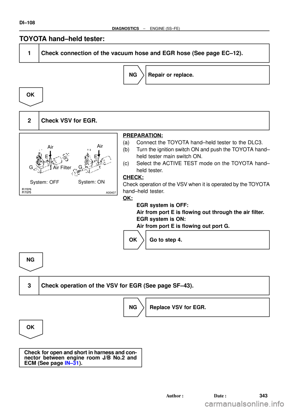
TOYOTA hand±held tester:
1 Check connection of the vacuum hose and EGR hose (See page EC±12).
NG Repair or replace.
OK
2 Check VSV for EGR.
PREPARATION:
(a) Connect the TOYOTA hand±held tester to the DLC3.
(b) Turn the ignition switch ON and push the TOYOTA hand±
held tester main switch ON.
(c) Select the ACTIVE TEST mode on the TOYOTA hand±
held tester.
CHECK:
Check operation of the VSV when it is operated by the TOYOTA
hand±held tester.
OK:
EGR system is OFF:
Air from port E is flowing out through the air filter.
EGR system is ON:
Air from port E is flowing out port G.
OK Go to step 4.
NG
3 Check operation of the VSV for EGR (See page SF±43).
NG Replace VSV for EGR.
OK
Check for open and short in harness and con-
nector between engine room J/B No.2 and
ECM (See page IN±31).
Page 1322 of 4592
A03017
A03418
ON
E9 Connector
EGR
OFF
Air
FilterON
Air
Air
E
G E
VSV is ON
VSV is OFF Air
G w/o Immobiliser
w/ Immobiliser
OFF
ON EGR
E8 Connector
DI±110
± DIAGNOSTICSENGINE (5S±FE)
345 Author�: Date�:
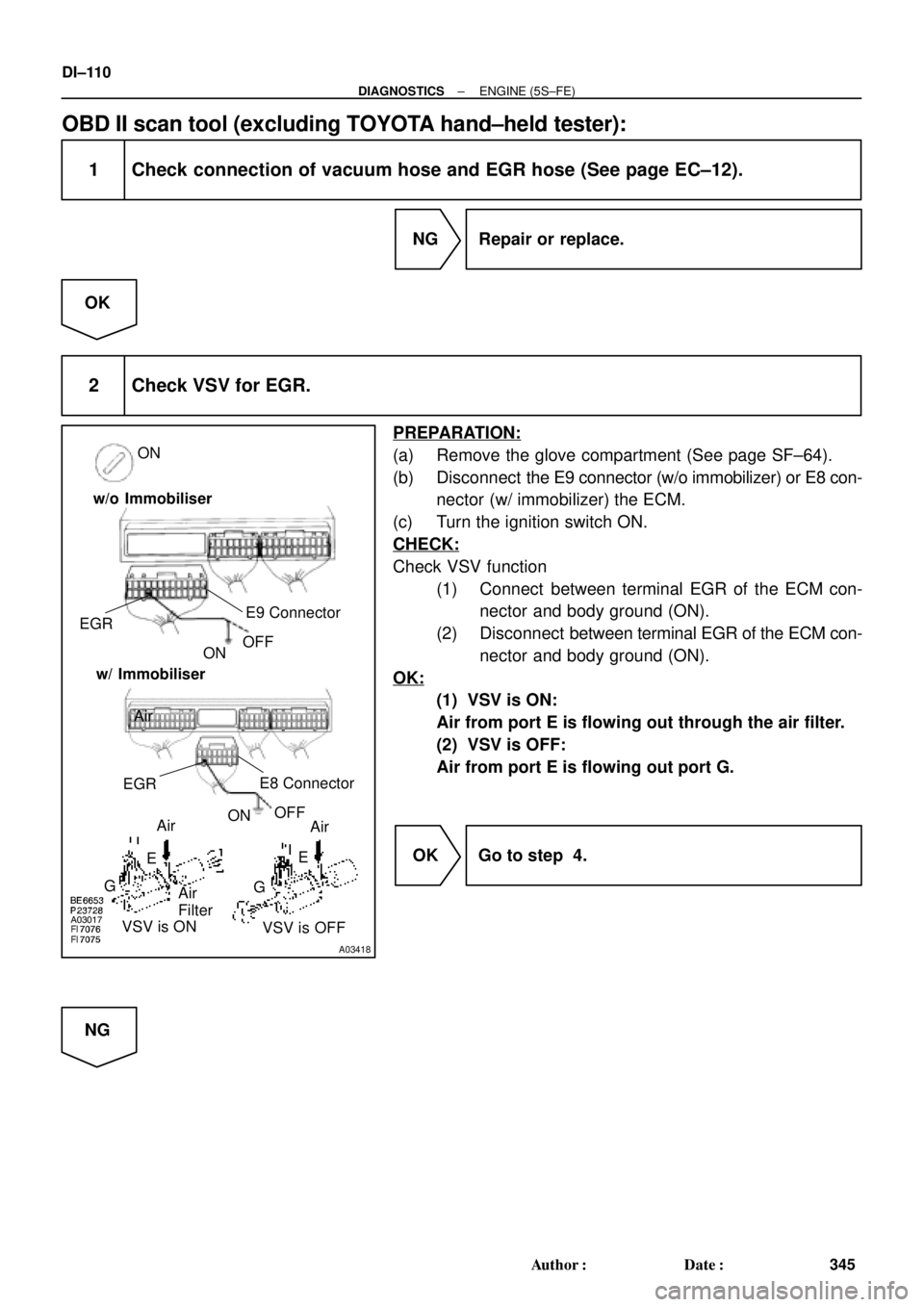
OBD II scan tool (excluding TOYOTA hand±held tester):
1 Check connection of vacuum hose and EGR hose (See page EC±12).
NG Repair or replace.
OK
2 Check VSV for EGR.
PREPARATION:
(a) Remove the glove compartment (See page SF±64).
(b) Disconnect the E9 connector (w/o immobilizer) or E8 con-
nector (w/ immobilizer) the ECM.
(c) Turn the ignition switch ON.
CHECK:
Check VSV function
(1) Connect between terminal EGR of the ECM con-
nector and body ground (ON).
(2) Disconnect between terminal EGR of the ECM con-
nector and body ground (ON).
OK:
(1) VSV is ON:
Air from port E is flowing out through the air filter.
(2) VSV is OFF:
Air from port E is flowing out port G.
OK Go to step 4.
NG
Page 1335 of 4592

A07552
3
2
1Y
P
BRECM
1
1
7
9
22 J19
J/C
8
E8
E8
EBE8
E01 E9
E8
EJ/C
J28
J27
10
1V
6
2F From
BatteryB±Y VSV
for EVAP
2V±W
VSV for Vapor
Pressure
Sensor
9
Engine Room J/B No.2 B±Y
EFI II3
53
B±Y
VC
PTNK
E2
EVP
TPC5 V
E1
E01
2J 2A
2K
2
*1: w/o Immobiliser
*2: w/ Immobiliser
(*1) (*2)
MREL(*2)
E8
8
E9
3
E8
16
E10
7 Y Y Vapor Pressure Sensor
P P
BR BR
E
ID1 ID1
1
V V
B±Y
B±W B±W
II4 II4
5
ID1
ID1
ID1
6 5
237
8
II4 II4
II2
(*1) (*2)(*1) (*2)
W±B
B±Y12
BB
B±Y
12
7 4
EFI Relay J27 J27B±Y
B
BJ/C
(*2) (*2)
B±R(*1)From
Ignition SW
± DIAGNOSTICSENGINE (5S±FE)
DI±123
358 Author�: Date�:
WIRING DIAGRAM
INSPECTION PROCEDURE
HINT:
�If DTC P0441 (Evaporative Emission Control System Incorrect Purge Flow), P0446 (Evaporative
Emission Control System Vent Control Malfunction), P0450 (Evaporative Emission Control System
Pressure Sensor Malfunction) or P0451 is output after DTC P0440 (Evaporative Emission Control Sys-
tem Malfunction), first troubleshoot DTC P0441, P0446, P0450 or P0451. If no malfunction is detected,
troubleshoot DTC P0440 next.
�Ask the customer whether, after the MIL came on, the customer found the fuel tank cap loose and tight-
ened it. Also ask the customer whether the fuel tank cap was loose when refuelling. If the fuel tank cap
was not loose, it was the cause of the DTC. If the fuel tank cap was not loose or if the customer was
not sure if it was loose, troubleshoot according to the following procedure.
�Read freeze frame data using TOYOTA hand±held tester or OBD II scan tool. Because freeze frame
records the engine conditions when the malfunction is detected, when troubleshooting it is useful for
determining whether the vehicle was running or stopped, the engine warmed up or not, the air±fuel
ratio lean or rich, etc. at the time of the malfunction.
�When the ENGINE RUN TIME in the freeze frame data is less than 200 seconds, carefully check the
VSV for EVAP, charcoal canister and vapor pressure sensor.
Page 1338 of 4592
A03008A03419
ON
E2
(±)VC
(+) w/o Immobiliser
w/ Immobiliser
E2
(±)VC
(+)
DI±126
± DIAGNOSTICSENGINE (5S±FE)
361 Author�: Date�:
8 Check charcoal canister (See page EC±6).
NG Replace charcoal canister.
OK
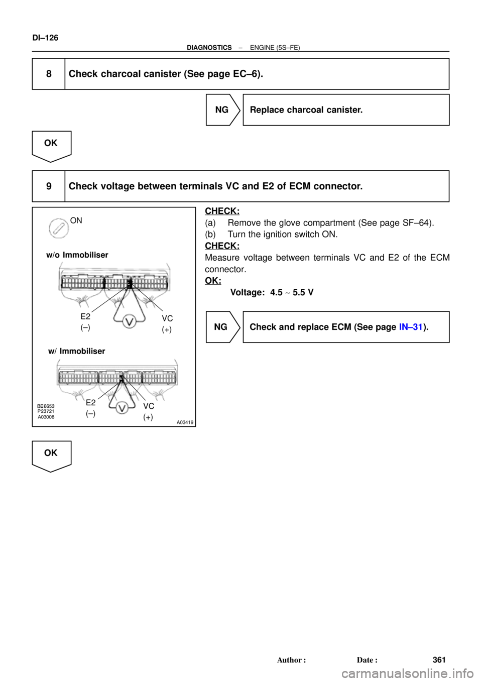
9 Check voltage between terminals VC and E2 of ECM connector.
CHECK:
(a) Remove the glove compartment (See page SF±64).
(b) Turn the ignition switch ON.
CHECK:
Measure voltage between terminals VC and E2 of the ECM
connector.
OK:
Voltage: 4.5 ~ 5.5 V
NG Check and replace ECM (See page IN±31).
OK
Page 1339 of 4592
A03018
A03420
PTNK (+)E2 (±)
(1)(2)
Vacuum ON
w/o Immobiliser
w/ Immobiliser
PTNK (+)
E2 (±)
± DIAGNOSTICSENGINE (5S±FE)
DI±127
362 Author�: Date�:
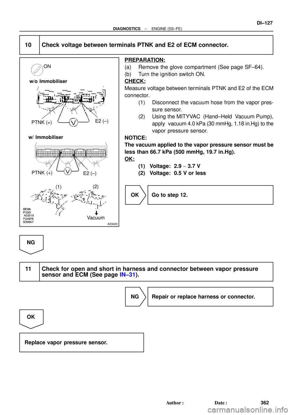
10 Check voltage between terminals PTNK and E2 of ECM connector.
PREPARATION:
(a) Remove the glove compartment (See page SF±64).
(b) Turn the ignition switch ON.
CHECK:
Measure voltage between terminals PTNK and E2 of the ECM
connector.
(1) Disconnect the vacuum hose from the vapor pres-
sure sensor.
(2) Using the MITYVAC (Hand±Held Vacuum Pump),
apply vacuum 4.0 kPa (30 mmHg, 1.18 in.Hg) to the
vapor pressure sensor.
NOTICE:
The vacuum applied to the vapor pressure sensor must be
less than 66.7 kPa (500 mmHg, 19.7 in.Hg).
OK:
(1) Voltage: 2.9 ~ 3.7 V
(2) Voltage: 0.5 V or less
OK Go to step 12.
NG
11 Check for open and short in harness and connector between vapor pressure
sensor and ECM (See page IN±31).
NG Repair or replace harness or connector.
OK
Replace vapor pressure sensor.
 (*2)
(*2)
*1: w")