Page 2004 of 4592

CIRCUIT DES")
N14677
Fuse
DI±792
± DIAGNOSTICSSUPPLEMENTAL RESTRAINT SYSTEM
1027 Author�: Date�:
SRS Warning Light Circuit Malfunction (Does not light up, when
ignition switch is turned to ACC or ON.)
CIRCUIT DESCRIPTION
The SRS warning light is located on the combination meter.
When the SRS is normal, the SRS warning light lights up for approx. 6 seconds after the ignition switch is
turned from LOCK position to ACC or ON position, and then turns off automatically.
If there is a malfunction in the SRS, the SRS warning light lights up to inform the driver of the abnormality.
When terminals Tc and E1 of the DLC1 are connected, the DTC is displayed by blinking the SRS warning
light.
WIRING DIAGRAM
See page DI±790.
INSPECTION PROCEDURE
1 Check ECU±B Fuse.
PREPARATION:
Remove ECU±B fuse.
CHECK:
Check continuity of ECU±B fuse.
OK:
Continuity
HINT:
�Fuse may be burnt out even if it appears to be OK during
visual inspection.
�If fuse is OK, install it.
NG Go to step 5.
OK
2 Prepare for inspection. (See step 1 on page DI±787)
DI1BP±08
Page 2005 of 4592
AB0119H01300
H01301
Airbag Sensor Assembly
ON
LA
(+)
(±)
± DIAGNOSTICSSUPPLEMENTAL RESTRAINT SYSTEM
DI±793
1028 Author�: Date�:
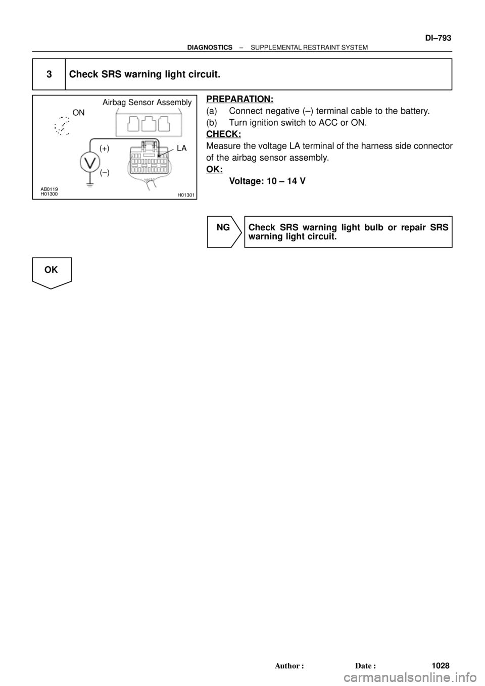
3 Check SRS warning light circuit.
PREPARATION:
(a) Connect negative (±) terminal cable to the battery.
(b) Turn ignition switch to ACC or ON.
CHECK:
Measure the voltage LA terminal of the harness side connector
of the airbag sensor assembly.
OK:
Voltage: 10 ± 14 V
NG Check SRS warning light bulb or repair SRS
warning light circuit.
OK
Page 2006 of 4592
AB0119H08325H02309H08324
Airbag
Sensor
Assembly
Side Airbag
Sensor (RH)Spiral
Cable
P Squib
D Squib
P/T Squib (LH)
Front Airbag
Sensor (LH)
Side Squib (RH)
ON
Side Airbag
Sensor (LH)
P/T Squib (RH)Side Squib (LH)
Front Airbag
Sensor (RH)
DI±794
± DIAGNOSTICSSUPPLEMENTAL RESTRAINT SYSTEM
1029 Author�: Date�:
4 Does SRS warning light come on?
PREPARATION:
(a) Disconnect negative (±) terminal cable from the battery.
(b) Connect the airbag sensor assembly connector.
(c) Connect negative (±) terminal cable to the battery, and
wait at least for 2 seconds.
(d) Turn ignition switch to ACC or ON.
CHECK:
Check operation of SRS warning light.
NO Check terminal LA of airbag sensor assembly.
If normal, replace airbag sensor assembly.
YES
From the results of the above inspection, the malfunctioning part can now be considered normal.
To make sure of this, use simulation method to check.
Page 2007 of 4592
± DIAGNOSTICSSUPPLEMENTAL RESTRAINT SYSTEM
DI±795
1030 Author�: Date�:
5 Is new ECU±B fuse burnt out again?
NO Using simulation method, reproduce malfunc-
tion symptoms. (See page IN±21)
YES
Check harness between ECU±B fuse and
SRS warning light.
Page 2008 of 4592
H08301
LG±R P±B
B
BJ3 Junction
ConnectorAirbag Sensor
Assembly
A2119
Tc
11
LG±R 11
Tc
E1DLC1
3 BR
A
J22 (1MZ±FE)
J23 (5S±FE)
Junction Connector
BR (*4)
ECEC BR A
Junction
Connector
6
J7B
J8 C
BR 3
E1Tc DLC2 LG±R (*1)
P±B (*2)
4
B II3
II3
BR
J22
Junction Connector
A A BR BR (*3)J26
Junction
ConnectorB
B
BR (*3)
*1: TMC Made
*2: TMMK Made
*3: California, 1MZ±FE
*4: Except California DI±796
± DIAGNOSTICSSUPPLEMENTAL RESTRAINT SYSTEM
1031 Author�: Date�:
Tc Terminal Circuit
CIRCUIT DESCRIPTION
By connecting terminals Tc and E1 of the DLC1 the airbag sensor assembly is set in the DTC output mode.
The DTCs are displayed by blinking the SRS warning light.
WIRING DIAGRAM
DI1BQ±08
Page 2009 of 4592
AB0117AB0118AB0119
H02309H02314
LOCK ACC
ON
or
AB0118
R14305AB0119
H00030
ACCON
or
E1
Tc
(+) (±)
± DIAGNOSTICSSUPPLEMENTAL RESTRAINT SYSTEM
DI±797
1032 Author�: Date�:
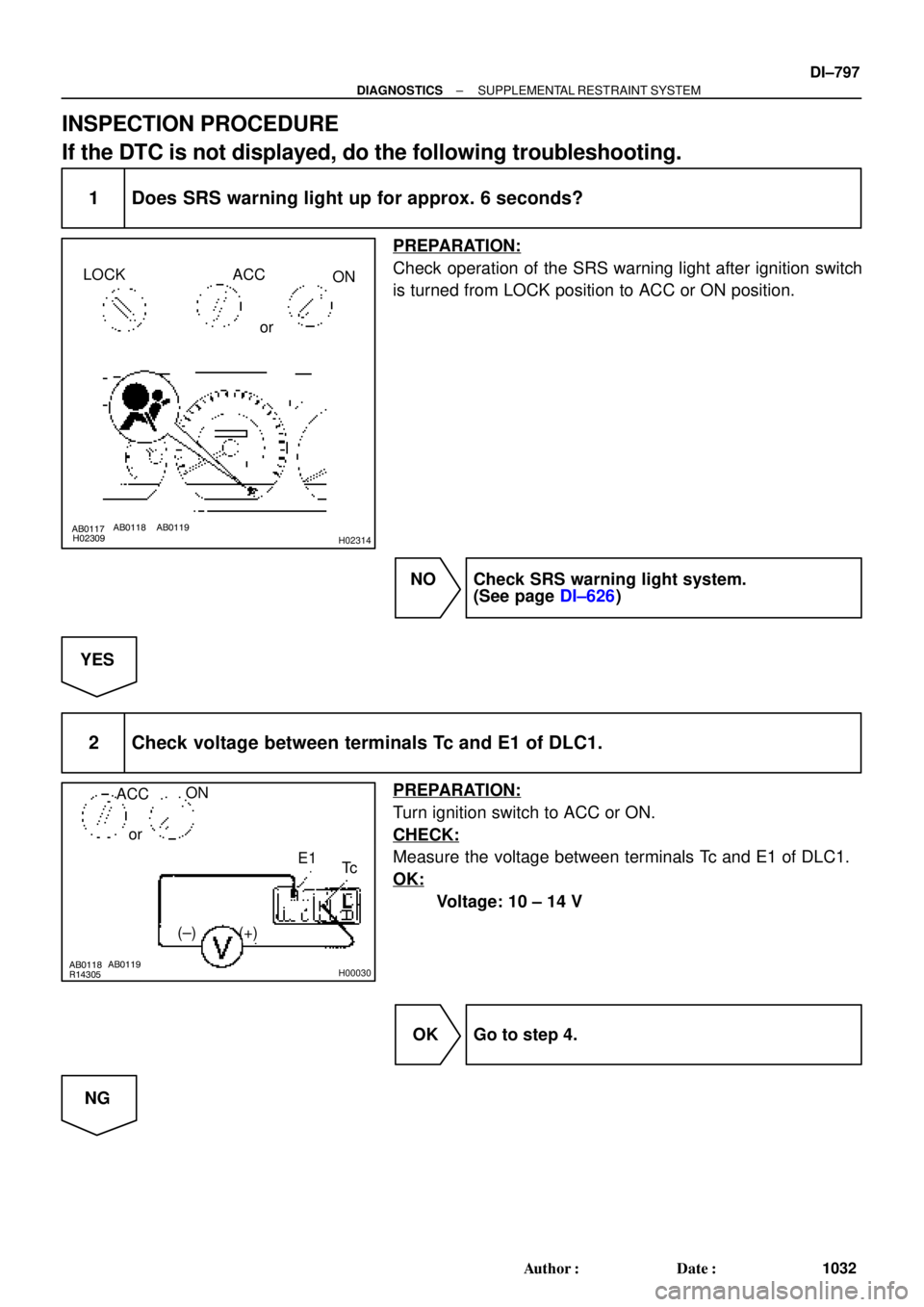
INSPECTION PROCEDURE
If the DTC is not displayed, do the following troubleshooting.
1 Does SRS warning light up for approx. 6 seconds?
PREPARATION:
Check operation of the SRS warning light after ignition switch
is turned from LOCK position to ACC or ON position.
NO Check SRS warning light system.
(See page DI±626)
YES
2 Check voltage between terminals Tc and E1 of DLC1.
PREPARATION:
Turn ignition switch to ACC or ON.
CHECK:
Measure the voltage between terminals Tc and E1 of DLC1.
OK:
Voltage: 10 ± 14 V
OK Go to step 4.
NG
Page 2010 of 4592

(±)
AB0117 AB0118 AB0119H01302H01303
LOCK
ACCON
or
Airbag Sensor Assembly
Tc
DI±798
± DIAGNOSTICSSUPPLEMENTAL RESTRAINT SYSTEM
1033 Author�: Date�:
3 Check")
AB0118
R14304AB0119
H00031
ACCON
orTc
(+)
(±)
AB0117 AB0118 AB0119H01302H01303
LOCK
ACCON
or
Airbag Sensor Assembly
Tc
DI±798
± DIAGNOSTICSSUPPLEMENTAL RESTRAINT SYSTEM
1033 Author�: Date�:
3 Check voltage between terminal Tc of DLC1 and body ground.
CHECK:
Measure the voltage between terminal Tc of DLC1 and body
ground.
OK:
Voltage: 10 ± 14 V
OK Check harness between terminal E1 of DLC1
and body ground.
NG
4 Check airbag sensor assembly.
PREPARATION:
(a) Turn ignition switch to LOCK.
(b) Disconnect negative (±) terminal cable from the battery,
and wait at least for 90 seconds.
(c) Disconnect the airbag sensor assembly connector.
(d) Insert service wire into terminal Tc from back side as
shown in the illustration.
(e) Connect the airbag sensor assembly connector with ser-
vice wire.
(f) Connect negative (±) terminal cable to the battery.
(g) Turn ignition switch to ACC or ON and wait at least for 20
seconds.
(h) Connect service wire of terminal Tc to body ground.
CHECK:
Check operation of SRS warning light.
OK:
SRS waning light comes on.
NOTICE:
Pay due attention to the terminal connecting position to
avoid a malfunction.
OK Check harness between the airbag sensor as-
sembly and DLC1.
NG
Replace airbag sensor assembly.
Page 2034 of 4592
N14695
CTY(+)
DI±822
± DIAGNOSTICSWIRELESS DOOR LOCK CONTROL SYSTEM
1057 Author�: Date�:
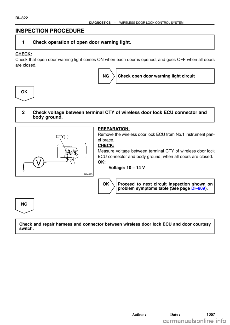
INSPECTION PROCEDURE
1 Check operation of open door warning light.
CHECK:
Check that open door warning light comes ON when each door is opened, and goes OFF when all doors
are closed.
NG Check open door warning light circuit
OK
2 Check voltage between terminal CTY of wireless door lock ECU connector and
body ground.
PREPARATION:
Remove the wireless door lock ECU from No.1 instrument pan-
el brace.
CHECK:
Measure voltage between terminal CTY of wireless door lock
ECU connector and body ground, when all doors are closed.
OK:
Voltage: 10 ± 14 V
OK Proceed to next circuit inspection shown on
problem symptoms table (See page DI±809).
NG
Check and repair harness and connector between wireless door lock ECU and door courtesy
switch.
Spiral
Cable
P Squib
D Squib
P/T Squib (LH)
Front Airbag
Sensor (LH)
Side Squib (RH)
ON
Side Airbag
Sensor (LH)
P/T Squib (RH)Si")


J23 (5S±FE)
Junction Connector
BR (*4)
ECEC BR A
Junction
Connector
6
J7B
J8 C
BR")