Page 2334 of 4592
DI03E±04
F01172
Sensor Rotor
ABS Warning Light
ABS ECU
DLC 1
Front Speed Sensor
ABS Actuator
ABS Solenoid
Relay
ABS Motor Relay
Sensor RotorFront Speed
Sensor
Stop Light SwitchDLC 2
Rear Speed Sensor DI±182
± DIAGNOSTICSANTI±LOCK BRAKE SYSTEM
PARTS LOCATION
Page 2335 of 4592

DI1JL±03
F07155
A13
A14
1 2 3 4 856 7 9 10 11 12 13
14 15 16 17 18 19 20 21 22 1 2 3 4 5 6
7 8 9 10 11 1223 24 25 26
± DIAGNOSTICSANTI±LOCK BRAKE SYSTEM
DI±183
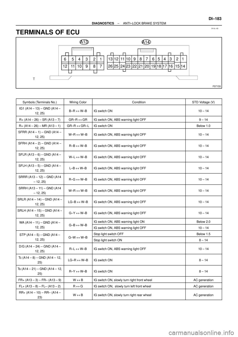
TERMINALS OF ECU
Symbols (Terminals No.)Wiring ColorConditionSTD Voltage (V)
IG1 (A14 ± 13) ± GND (A14 ±
12, 25)B±R e W±BIG switch ON10 ± 14
R+ (A14 ± 26) ± SR (A13 ± 7)GR±R eGRIG switch ON, ABS warning light OFF9 ± 14
R+ (A14 ± 26) ± MR (A13 ± 1)GR±R eGR±LIG switch ONBelow 1.0
SFRR (A14 ± 1) ± GND (A14 ±
12, 25)W±R e W±BIG switch ON, ABS warning light OFF10 ± 14
SFRH (A14 ± 2) ± GND (A14 ±
12, 25)R±B e W±BIG switch ON, ABS warning light OFF10 ± 14
SFLR (A13 ± 6) ± GND (A14 ±
12, 25)W±L e W±BIG switch ON, ABS warning light OFF10 ± 14
SFLH (A13 ± 5) ± GND (A14 ±
12, 25)L±B e W±BIG switch ON, ABS warning light OFF10 ± 14
SRRR (A13 ± 12) ± GND (A14
± 12, 25)R±G e W±BIG switch ON, ABS warning light OFF10 ± 14
SRRH (A13 ± 11) ± GND (A14
± 12, 25)W±R e W±BIG switch ON, ABS warning light OFF10 ± 14
SRLR (A14 ± 14) ± GND (A14 ±
12, 25)LG±B e W±BIG switch ON, ABS warning light OFF10 ± 14
SRLH (A14 ± 15) ± GND (A14 ±
12, 25)G±Y e W±BIG switch ON, ABS warning light OFF10 ± 14
WA (A14 ± 11) ± GND (A14 ±GBWBIG switch ON, ABS warning light ONBelow 2.0WA (A14 11 ) GND (A14
12, 25)G±B e W±BIG switch ON, ABS warning light OFF10 ± 14
STP (A14 ± 5) ± GND (A14 ±GWWBStop light switch OFFBelow 1.5STP (A14 5) GND (A14
12, 25)G±W e W±BStop light switch ON8 ± 14
D/G (A14 ± 24) ± GND (A14 ±
12, 25)R±L e W±BIG switch ON, ABS warning light OFF10 ± 14
Tc (A14 ± 8) ± GND (A14 ± 12,
25)LG±R e W±BIG switch ON8 ± 14
Ts (A14 ± 21) ± GND (A14 ± 12,
25)R±Y e W±BIG switch ON8 ± 14
FR+ (A13 ± 3) ± FR± (A13 ± 9)W e BIG switch ON, slowly turn right front wheelAC generation
FL+ (A13 ± 8) ± FL± (A13 ± 2)R e GIG switch ON, slowly turn left front wheelAC generation
RR+ (A14 ± 10) ± RR± (A14 ±
23)W eBIG switch ON, slowly turn right rear wheelAC generation
Page 2337 of 4592

DI03G±05
± DIAGNOSTICSANTI±LOCK BRAKE SYSTEM
DI±185
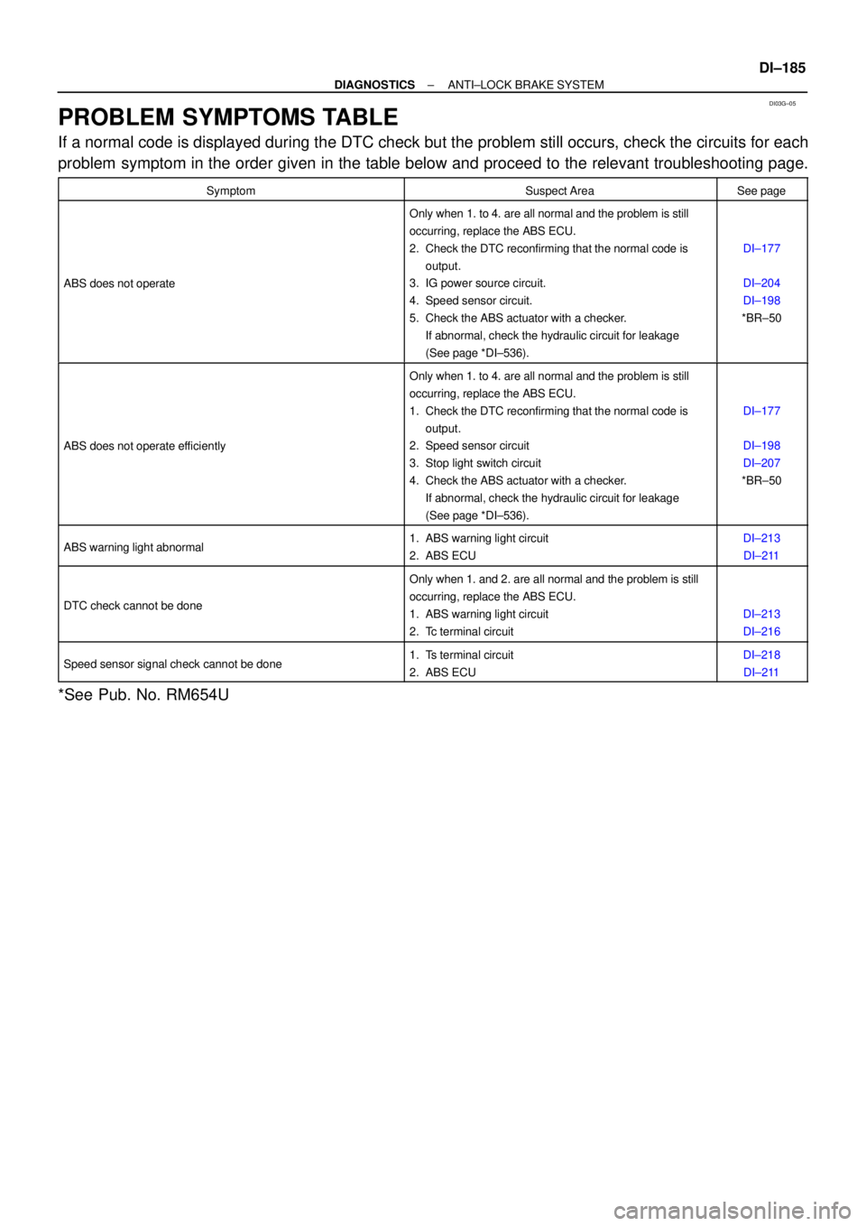
PROBLEM SYMPTOMS TABLE
If a normal code is displayed during the DTC check but the problem still occurs, check the circuits for each
problem symptom in the order given in the table below and proceed to the relevant troubleshooting page.
SymptomSuspect AreaSee page
ABS does not operate
Only when 1. to 4. are all normal and the problem is still
occurring, replace the ABS ECU.
2. Check the DTC reconfirming that the normal code is
output.
3. IG power source circuit.
4. Speed sensor circuit.
5. Check the ABS actuator with a checker.
If abnormal, check the hydraulic circuit for leakage
(See page *DI±536).
DI±177
DI±204
DI±198
*BR±50
ABS does not operate efficiently
Only when 1. to 4. are all normal and the problem is still
occurring, replace the ABS ECU.
1. Check the DTC reconfirming that the normal code is
output.
2. Speed sensor circuit
3. Stop light switch circuit
4. Check the ABS actuator with a checker.
If abnormal, check the hydraulic circuit for leakage
(See page *DI±536).
DI±177
DI±198
DI±207
*BR±50
ABS warning light abnormal1. ABS warning light circuit
2. ABS ECUDI±213
DI±211
DTC check cannot be done
Only when 1. and 2. are all normal and the problem is still
occurring, replace the ABS ECU.
1. ABS warning light circuit
2. Tc terminal circuit
DI±213
DI±216
Speed sensor signal check cannot be done1. Ts terminal circuit
2. ABS ECUDI±218
DI±211
*See Pub. No. RM654U
Page 2363 of 4592
± DIAGNOSTICSANTI±LOCK BRAKE SYSTEM
DI±211
DTC Always ON ABS ECU Malfunction
CIRCUIT DESCRIPTION
DTC No.DTC Detecting ConditionTrouble Area
Always ONABS ECU internal malfunction is detected.�ECU
�Battery
Fail safe function:
If trouble occurs in the power source circuit, the ECU cuts off current to the ABS solenoid relay and prohibits
ABS control.
INSPECTION PROCEDURE
1 Is DTC output?
Check DTC on page DI±177.
YES Repair circuit indicated by the code output.
NO
2 Is normal code displayed?
YES Check ABS solenoid relay. Check for short cir-
cuit in harness and connector between ABS so-
lenoid relay and DLC1 (See page IN±29).
NO
3 Is ABS warning light go off?
YES Check for open or short circuit in harness and
connector between ECU±IG fuse and ABS ECU
(See page IN±29).
NO
DI03P±05
Page 2364 of 4592
DI±212
± DIAGNOSTICSANTI±LOCK BRAKE SYSTEM
4 Check battery positive voltage.
CHECK:
Check the battery positive voltage.
OK:
10 ± 14 V
NG Check and repair the charging system (See Pub.
No. RM654U on page CH±1).
OK
5 Check ABS warning light.
PREPARATION:
(a) Disconnect the connector from the ABS ECU.
(b) Turn the ignition switch ON.
CHECK:
Check the ABS warning light goes off.
OK Check and replace ABS ECU.
NG
Check for short circuit in harness and connector between ABS warning light, DLC1, DLC2, and
ABS ECU (See page IN±29).
Page 2365 of 4592

F07217
Engine Room R/B No. 3
ABS Solenoid Relay
3
ABS
Actuator
A4 1
2
5 BatteryGAUGE Instrument Panel J/B
J/C
J3
D
ABS ECU 33 3 3
EA34 6
ABS ECUD
IJ28
R±L
IG3 4
DLC1 R±L
G±B
IG3 5 Short
Pin
W±B
ABS ECU W±L
G±B
C
CC R±L
R±L 1D2
7
4
R±L
A14WA IF1 12
11 G±B 4
G±B C12
C12
J/C
J22ABS Warning
Light
23
22 R±L
± DIAGNOSTICSANTI±LOCK BRAKE SYSTEM
DI±213
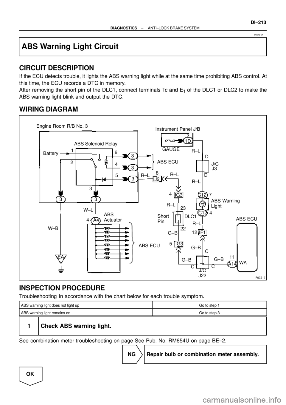
ABS Warning Light Circuit
CIRCUIT DESCRIPTION
If the ECU detects trouble, it lights the ABS warning light while at the same time prohibiting ABS control. At
this time, the ECU records a DTC in memory.
After removing the short pin of the DLC1, connect terminals Tc and E
1 of the DLC1 or DLC2 to make the
ABS warning light blink and output the DTC.
WIRING DIAGRAM
INSPECTION PROCEDURE
Troubleshooting in accordance with the chart below for each trouble symptom.
ABS warning light does not light upGo to step 1
ABS warning light remains onGo to step 3
1 Check ABS warning light.
See combination meter troubleshooting on page See Pub. No. RM654U on page BE±2.
NG Repair bulb or combination meter assembly.
OK
DI03Q±04
Page 2367 of 4592
± DIAGNOSTICSANTI±LOCK BRAKE SYSTEM
DI±215
3 Is DTC output?
Check DTC on page DI±177.
YES Repair circuit indicated by the code output.
NO
4 Does ABS warning light go off if short pin is removed?
NO Check for short circuit in harness and connec-
tor between ABS warning light, DLC1 and ABS
ECU (See page IN±29).
YES
5 Check ABS solenoid relay (See step 2).
NG Replace ABS solenoid relay.
OK
Check for short circuit in harness and connector between DLC1 and ABS solenoid relay (See
page IN±29).
Page 2368 of 4592
F00113
EC
BRTc LG±R
AA A BRIG36
BR
311 DLC1Tc
E
1
Tc E1
LG±RLG±R
IG311 BRC
BJ/C
BRDLC2
34LG±R
BB
BABS ECU
J7 J6
J20
J/C
EC
BRTc 8
LG±R
AA A BR6
BR
311 DLC1Tc
E
1
Tc E1
LG±RLG±R 11 BRC
BJ/C
BRDLC2
34LG±R
BB
BABS ECU
J/C
J2
A14
F02607 F00445F02612
DLC2
DLC1
Tc E
1
Tc E
1
DI±216
± DIAGNOSTICSANTI±LOCK BRAKE SYSTEM
Tc Terminal Circuit
CIRCUIT DESCRIPTION
Connecting between terminals Tc and E1 of the DLC1 or the DLC2 causes the ECU to display the DTC by
flashing the ABS warning light.
WIRING DIAGRAM
INSPECTION PROCEDURE
1 Check voltage between terminals Tc and E1 of DLC2 or DLC1.
CHECK:
(a) Turn the ignition switch ON.
(b) Measure voltage between terminals Tc and E
1 of DLC2 or
DLC1.
OK:
Voltage: 10 ± 14 V
OK If ABS warning light does not blink even after Tc
and E
1 are connected, the ECU may be defec-
tive.
NG
DI03R±04