Page 2463 of 4592
H02755AB0119H10313H10308
ON P/T Squib (LH)
Front Airbag
Sensor (RH)Spiral
Cable
P/T Squib (RH) Front Airbag
Sensor (LH)
P Squib D SquibAirbag Sensor
Assembly
± DIAGNOSTICSSUPPLEMENTAL RESTRAINT SYSTEM
DI±311
4 Does SRS warning light come on?
PREPARATION:
(a) Disconnect negative (±) terminal cable from the battery.
(b) Connect the airbag sensor assembly connector.
(c) Connect negative (±) terminal cable to the battery, and
wait at least for 2 seconds.
(d) Turn ignition switch to ACC or ON.
CHECK:
Check operation of SRS warning light.
NO Check terminal LA of airbag sensor assembly.
If normal, replace airbag sensor assembly.
YES
From the results of the above inspection, the malfunctioning part can now be considered normal.
To make sure of this, use simulation method to check.
Page 2464 of 4592
DI±312
± DIAGNOSTICSSUPPLEMENTAL RESTRAINT SYSTEM
5 Is new ECU±B fuse burnt out again?
NO Using simulation method, reproduce malfunc-
tion symptoms. (See page IN±19)
YES
Check harness between ECU±B fuse and
SRS warning light.
Page 2465 of 4592
H08301H10309
LG±R P±B
B
BJ2 Junction
ConnectorAirbag Sensor
Assembly
C519
Tc
11
LG±R 11
Tc
E1DLC1
3 BR
A
BR
ECEC BR A
Junction
Connector
6
J6B
J7 C
BR 3
E1Tc DLC2 LG±R
4
B IG3
IG3
BR
J20
Junction Connector
A A BR J20
Junction Connector
± DIAGNOSTICSSUPPLEMENTAL RESTRAINT SYSTEM
DI±313
Tc Terminal Circuit
CIRCUIT DESCRIPTION
By connecting terminals Tc and E1 of the DLC1 the airbag sensor assembly is set in the DTC output mode.
The DTCs are displayed by blinking the SRS warning light.
WIRING DIAGRAM
DI1BQ±12
Page 2466 of 4592
AB0117AB0118AB0119H10313H10315
LOCK ACC
ON
or
AB0118
R14305AB0119
H00030
ACCON
or
E1
Tc
(+) (±)
DI±314
± DIAGNOSTICSSUPPLEMENTAL RESTRAINT SYSTEM
INSPECTION PROCEDURE
If the DTC is not displayed, do the following troubleshooting.
1 Does SRS warning light up for approx. 6 seconds?
PREPARATION:
Check operation of the SRS warning light after ignition switch
is turned from LOCK position to ACC or ON position.
NO Check SRS warning light system.
(See page DI±223)
YES
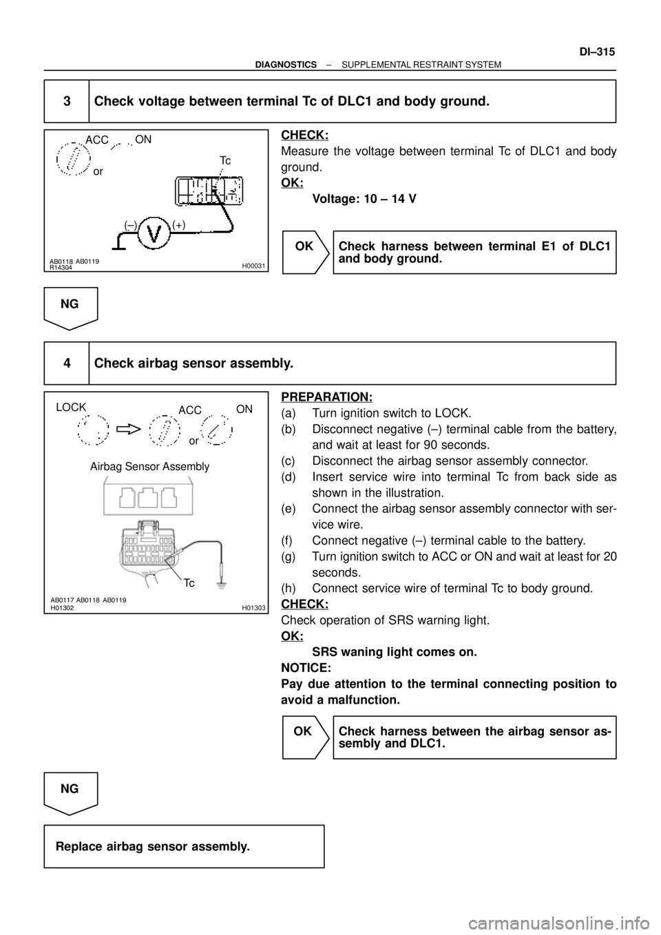
2 Check voltage between terminals Tc and E1 of DLC1.
PREPARATION:
Turn ignition switch to ACC or ON.
CHECK:
Measure the voltage between terminals Tc and E1 of DLC1.
OK:
Voltage: 10 ± 14 V
OK Go to step 4.
NG
Page 2467 of 4592

AB0118
R14304AB0119
H00031
ACCON
orTc
(+)
(±)
AB0117 AB0118 AB0119H01302H01303
LOCK
ACCON
or
Airbag Sensor Assembly
Tc
± DIAGNOSTICSSUPPLEMENTAL RESTRAINT SYSTEM
DI±315
3 Check voltage between terminal Tc of DLC1 and body ground.
CHECK:
Measure the voltage between terminal Tc of DLC1 and body
ground.
OK:
Voltage: 10 ± 14 V
OK Check harness between terminal E1 of DLC1
and body ground.
NG
4 Check airbag sensor assembly.
PREPARATION:
(a) Turn ignition switch to LOCK.
(b) Disconnect negative (±) terminal cable from the battery,
and wait at least for 90 seconds.
(c) Disconnect the airbag sensor assembly connector.
(d) Insert service wire into terminal Tc from back side as
shown in the illustration.
(e) Connect the airbag sensor assembly connector with ser-
vice wire.
(f) Connect negative (±) terminal cable to the battery.
(g) Turn ignition switch to ACC or ON and wait at least for 20
seconds.
(h) Connect service wire of terminal Tc to body ground.
CHECK:
Check operation of SRS warning light.
OK:
SRS waning light comes on.
NOTICE:
Pay due attention to the terminal connecting position to
avoid a malfunction.
OK Check harness between the airbag sensor as-
sembly and DLC1.
NG
Replace airbag sensor assembly.
Page 2814 of 4592

W02655
Marks
± INTRODUCTIONFOR ALL OF VEHICLES
IN±11
11 Author�: Date�:
(3) Even in cases of a minor collision where the SRS
does not deploy, the steering wheel pad, front pas-
senger airbag assembly, side airbag assembly and
seat belt pretensioner should be inspected (See
page RS±16, RS±29, and BO±127).
(4) Never use SRS parts from another vehicle. When
replacing parts, replace them with new parts.
(5) Before repairs, remove the airbag sensor if shocks
are likely to be applied to the sensor during repairs.
(6) Never disassemble and repair the airbag sensor as-
sembly, steering wheel pad, front passenger airbag
assembly, side airbag assembly or seat belt preten-
sioner.
(7) If the airbag sensor assembly, steering wheel pad,
front passenger airbag assembly, side airbag as-
sembly or seat belt pretensioner has been dropped,
or if there are cracks, dents or other defects in the
case, bracket or connector, replace them with new
ones.
(8) Do not directly expose the airbag sensor assembly,
steering wheel pad, front passenger airbag assem-
bly, side airbag assembly or seat belt pretensioner
to hot air or flames.
(9) Use a volt/ohmmeter with high impedance (10 kW/V
minimum) for troubleshooting of the electrical cir-
cuit.
(10) Information labels are attached to the periphery of
the SRS components. Follow the instructions on the
notices.
(11) After work on the supplemental restraint system is
completed, check the SRS warning light (See page
DI±626).
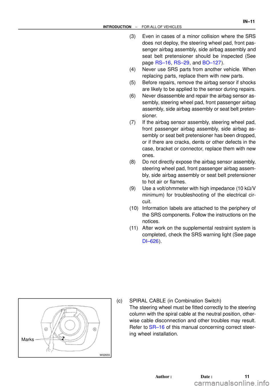
(c) SPIRAL CABLE (in Combination Switch)
The steering wheel must be fitted correctly to the steering
column with the spiral cable at the neutral position, other-
wise cable disconnection and other troubles may result.
Refer to SR±16 of this manual concerning correct steer-
ing wheel installation.
Page 2857 of 4592

W02655
Marks
± INTRODUCTIONFOR ALL OF VEHICLES
IN±11
11 Author�: Date�:
(3) Even in cases of a minor collision where the SRS
does not deploy, the steering wheel pad, front pas-
senger airbag assembly and seat belt pretensioner
should be inspected (See Pub. No. RM654U on
page SR±16, RS±29 and BO±127).
(4) Never use SRS parts from another vehicle. When
replacing parts, replace them with new parts.
(5) Before repairs, remove the airbag sensor if shocks
are likely to be applied to the sensor during repairs.
(6) Never disassemble and repair the airbag sensor as-
sembly, steering wheel pad, front passenger airbag
assembly or seat belt pretensioner.
(7) If the airbag sensor assembly, steering wheel pad,
front passenger airbag assembly or seat belt pre-
tensioner has been dropped, or if there are cracks,
dents or other defects in the case, bracket or con-
nector, replace them with new ones.
(8) Do not directly expose the airbag sensor assembly,
steering wheel pad, front passenger airbag assem-
bly or seat belt pretensioner to hot air or flames.
(9) Use a volt/ohmmeter with high impedance (10 kW/V
minimum) for troubleshooting of the electrical cir-
cuit.
(10) Information labels are attached to the periphery of
the SRS components. Follow the instructions on the
notices.
(11) After work on the supplemental restraint system is
completed, check the SRS warning light (See page
DI±223).
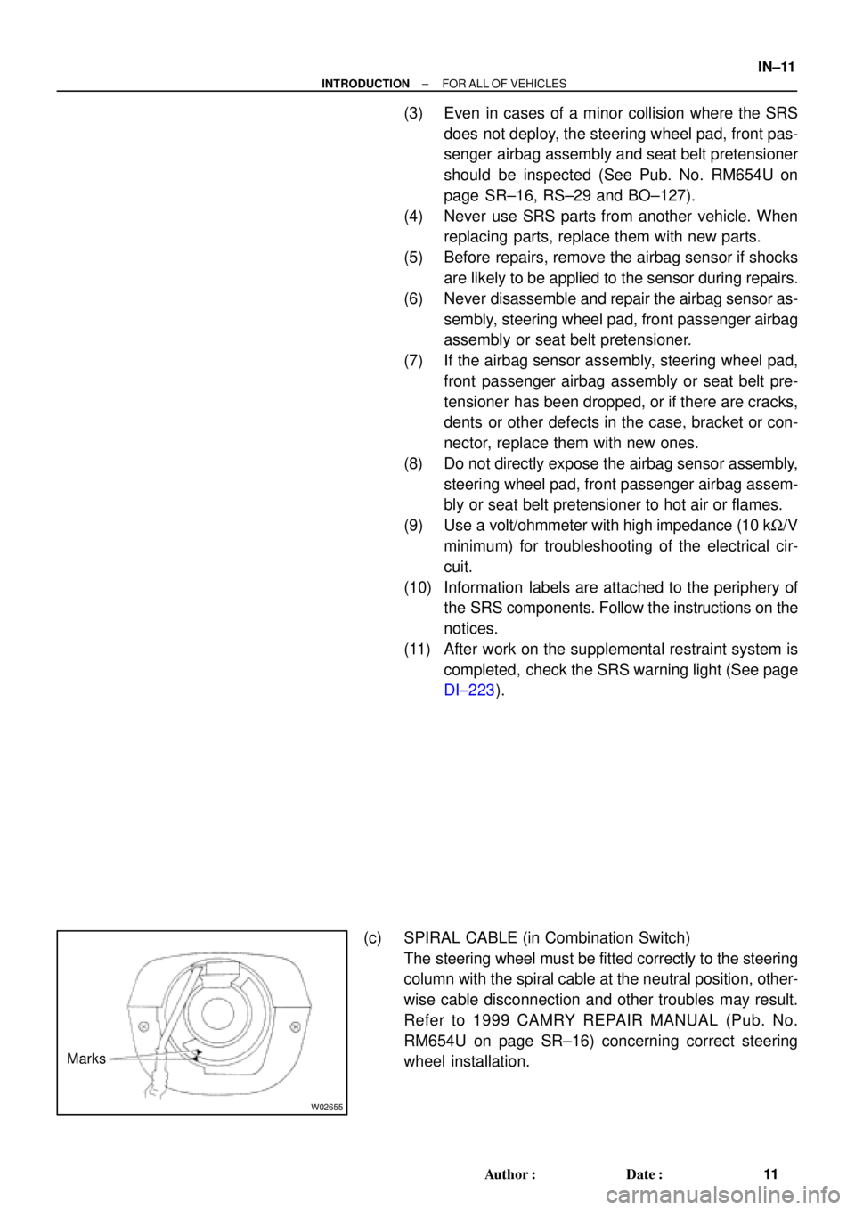
(c) SPIRAL CABLE (in Combination Switch)
The steering wheel must be fitted correctly to the steering
column with the spiral cable at the neutral position, other-
wise cable disconnection and other troubles may result.
Refer to 1999 CAMRY REPAIR MANUAL (Pub. No.
RM654U on page SR±16) concerning correct steering
wheel installation.
Page 2925 of 4592

MA002±11
MA±2
± MAINTENANCEINSIDE VEHICLE
45 Author�: Date�:
INSIDE VEHICLE
GENERAL MAINTENANCE
These are maintenance and inspection items which are considered to be the owner's responsibility.
They can be done by the owner or they can have them done at a service shop.
These items include those which should be checked on a daily basis, those which, in most cases, do not
require (special) tools and those which are considered to be reasonable for the owner to do.
Items and procedures for general maintenance are as follows.
1. GENERAL NOTES
�Maintenance items may vary from country to country. Check the owner's manual supplement in which
the maintenance schedule is shown.
�Every service item in the periodic maintenance schedule must be performed.
�Periodic maintenance service must be performed according to whichever interval in the periodic main-
tenance schedule occurs first, the odometer reading (miles) or the time interval (months).
�Maintenance service after the last period should be performed at the same interval as before unless
otherwise noted.
�Failure to do even one item an cause the engine to run poorly and increase exhaust emissions.
2. LIGHTS
(a) Check that the headlights, stop lights, taillights, turn signal lights, and other lights are all working.
(b) Check the headlight aim.
3. WARNING LIGHTS AND BUZZERS
Check that all warning lights and buzzers function properly.
4. HORN
Check that it is working.
5. WINDSHIELD GLASS
Check for scratches, pits or abrasions.
6. WINDSHIELD WIPER AND WASHER
(a) Check operation of the wipers and washer.
(b) Check that the wipers do not streak.
7. WINDSHIELD DEFROSTER
Check that air comes out from the defroster outlet when operating the heater or air conditioner.
8. REAR VIEW MIRROR
Check that it is mounted securely.
9. SUN VISORS
Check that they move freely and are mounted securely.
10. STEERING WHEEL
Check that it has the specified freeplay. Be alert for changes in steering condition, such as hard steering,
excessive freeplay or strange noises.
11. SEATS
(a) Check that the seat adjusters operate smoothly.
(b) Check that all latches lock securely in any position.
(c) Check that the head restraints move up and down smoothly and that the locks hold securely in any
latch position.
(d) For fold±down seat backs, check that the latches lock securely.
12. SEAT BELTS
(a) Check that the seat belt system such as the buckles, retractors and anchors operate properly and
smoothly.
(b) Check that the belt webbing is not cut, frayed, worn or damaged.