Page 4093 of 4592

TAILLIGHT
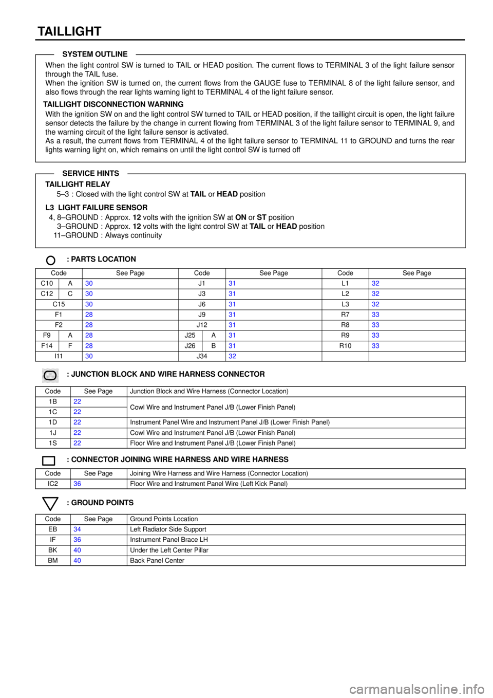
When the light control SW is turned to TAIL or HEAD position. The current flows to TERMINAL 3 of the light failure sensor
through the TAIL fuse.
When the ignition SW is turned on, the current flows from the GAUGE fuse to TERMINAL 8 of the light failure sensor, and
also flows through the rear lights warning light to TERMINAL 4 of the light failure sensor.
TAILLIGHT DISCONNECTION WARNING
With the ignition SW on and the light control SW turned to TAIL or HEAD position, if the taillight circuit is open, the light failure
sensor detects the failure by the change in current flowing from TERMINAL 3 of the light failure sensor to TERMINAL 9, and
the warning circuit of the light failure sensor is activated.
As a result, the current flows from TERMINAL 4 of the light failure sensor to TERMINAL 11 to GROUND and turns the rear
lights warning light on, which remains on until the light control SW is turned off
TAILLIGHT RELAY
5±3 : Closed with the light control SW at TAIL or HEAD position
L3 LIGHT FAILURE SENSOR
4, 8±GROUND : Approx. 12 volts with the ignition SW at ON or ST position
3±GROUND : Approx. 12 volts with the light control SW at TAIL or HEAD position
11±GROUND : Always continuity
: PARTS LOCATION
CodeSee PageCodeSee PageCodeSee Page
C10A30J131L132
C12C30J331L232
C1530J631L332
F128J931R733
F228J1231R833
F9A28J25A31R933
F14F28J26B31R1033
I1130J3432
������ ���: JUNCTION BLOCK AND WIRE HARNESS CONNECTOR
CodeSee PageJunction Block and Wire Harness (Connector Location)
1B22Cowl Wire and Instrument Panel J/B (Lower Finish Panel)1C22Cowl Wire and Instrument Panel J/B (Lower Finish Panel)
1D22Instrument Panel Wire and Instrument Panel J/B (Lower Finish Panel)
1J22Cowl Wire and Instrument Panel J/B (Lower Finish Panel)
1S22Floor Wire and Instrument Panel J/B (Lower Finish Panel)
: CONNECTOR JOINING WIRE HARNESS AND WIRE HARNESS
CodeSee PageJoining Wire Harness and Wire Harness (Connector Location)
IC236Floor Wire and Instrument Panel Wire (Left Kick Panel)
: GROUND POINTS
CodeSee PageGround Points Location
EB34Left Radiator Side Support
IF36Instrument Panel Brace LH
BK40Under the Left Center Pillar
BM40Back Panel Center
SYSTEM OUTLINE
SERVICE HINTS
Page 4120 of 4592
A1 2 1 2 1D 21C7 1J 9
IK1 1 IK1 2 IB1 9 IB1 3
2 1 2 1 B 22 B9J24
10 B23 B 13 B5 B 11FROM POWER SOURCE SYSTEM (
SEE PAGE 44)
R±L
B±R B±R
G±W G±WR±L
R
G G R
W
BW
B
ABS SPEED SENSOR
FRONT LHABS SPEED SENSOR
FRONT RH D D10A
GAUGE
ABS WARNING
LIGHT
[COMB. METER]
ABS SPEED SENSOR
REAR LHABS SPEED SENSOR
REAR RH 15A
ECU±IG15A
STOP
ABS ECUA 6 A 7R±L
J 3
JUNCTION
CONNECTOR
C12
B
B J23
A19 A201R 51R 4
STOP LIGHT SW
W G± W1 2S 4
IFB 12 B 25
A
JUNCTION
CONNECTOR J 9
W±B W±B
IF1 12
C7
C4
G±B G± B
B CA A
C CCIJ2 1IJ26
A 9 A 3 A 2 A 8
R
G
W
BGRJUNCTION
CONNECTOR JUNCTION
CONNECTOR J22
JUNCTION
CONNECTOR J12
G± B
GND GND,
B A13 A , A14
WA IG1 STP FL+ FL± FR+ FR±
RL+ RL± RR+ RR±
Page 4124 of 4592

SRS
NOTICE: When inspecting or repairing the SRS, perform the operation in accordance with the following precautionary
instructions and the procedure and precautions in the Repair Manual for the applicable model year.
�Malfunction symptoms of the SRS are difficult to confirm, so the DTCs become the most important source of information
when troubleshooting. When troubleshooting the SRS, always inspect the DTCs before disconnecting the battery.
�Work must be started after 90 seconds from when the ignition switch is turned to the ºLOCKº position and the
negative (±) terminal cable is disconnected from the battery.
(The SRS is equipped with a back±up power source so that if work is started within 90 seconds from
disconnecting the negative (±) terminal cable of the battery, the SRS may be deployed.)
�When the negative (±) terminal cable is disconnected from the battery, the memory of the clock and audio system will be
canceled. So before starting work, make a record of the contents memorized in the audio memory system. When work is
finished, reset the audio systems as they were before and adjust the clock. To avoid erasing the memory in each
memory system, never use a back±up power supply from outside the vehicle.
�Before repairs, remove the airbag sensor if shocks are likely to be applied to the sensor during repairs.
�Do not expose the steering wheel pad, front passenger airbag assembly, seat belt pretensioner, center airbag sensor
assembly or front airbag sensor assembly directly to hot air or flames.
�Even in cases of a minor collision where the SRS does not deploy, the steering wheel pad, front passenger airbag
assembly, seat belt pretensioner, center airbag sensor assembly and front airbag sensor assembly should be inspected.
�Never use SRS parts from another vehicle. When replacing parts, replace them with new parts.
�Never disassemble and repair the steering wheel pad, front passenger airbag assembly, seat belt pretensioner, center
airbag sensor assembly or front airbag sensor assembly in order to reuse it.
�If the steering wheel pad, front passenger airbag assembly, seat belt pretensioner, center airbag sensor assembly or
front airbag sensor assembly has been dropped, or if there are cracks, dents or other defects in the case, bracket or
connector, replace them with new ones.
�Use a volt/ohmmeter with high impedance (10 kW/V minimum) for troubleshooting the system's electrical circuits.
�Information labels are attached to the periphery of the SRS components. Follow the instructions on the notices.
�After work on the SRS is completed, perform the SRS warning light check.
�If the vehicle is equipped with a mobile communication system, refer to the precaution in the IN section of the Repair
Manual.
Page 4126 of 4592
2 1A 2A1
2 1C 5C6 13 12
IE2 2
A AIG3 7IG311
C C
IG3 6
A A
EC B 12 B 3B19 511 3
B
3 AB
B
4
7
A AB TC E1
E1 TC
SILLG
LG±R
BR LG
LG±R B±Y
P±B
LG±R BR BR BR BRW Y Y±B
W
BR
W±R
LG
PRETENSIONER
LH P13
PRETENSIONER
RH P14JUNCTION
CONNECTOR J 2
JUNCTION
CONNECTOR J 2
DATA LINK
CONNECTOR 3 D 3
DATA LINK
CONNECTOR 2 D 2LG
C 4
CENTER AIRBAG SENSOR ASSEMBLYB A, C 5
C , C 6
Y±B
Y
PL+ PL± PR+ PR± SILLA TC
JUNCTION
CONNECTOR J20A CAC
B B
(
SHIELDED)
BR
J 6
JUNCTION
CONNECTORB A, J 7
DATA LINK
CONNECTOR 1 D 1
SRS WARNING
LIGHT
[COMB. METER] C11
I 1
Page 4135 of 4592
KEY REMINDER AND SEAT BELT WARNING
2 1
12J 12 1D2
1T 3
1M 51S71S4
1J 71M 3DD
1W 1
IFBK
R±W
R L±B W± B
R±G W±B
R±L R±LFROM POWER SOURCE SYSTEM (
SEE PAGE 44)
10A
GAU GE7. 5A
DOME
SEAT BELT
WARNING LIGHT
[COMB. METER]JUNCTION
CONNECTOR
UNLOCK
WARNING SW
DOOR COURTESY
SW FRONT LH J 3
U 1
D 7
A
JUNCTION
CONNECTOR J34 A
JUNCTION
CONNECTOR J 9971
8 6 5 10C 7
A 4
BUZZER C C10 A , C12
2 1
R±Y W±B
BUCKLE
SW LH B 5 25A
DOOR
1D 1
B C
A A
A 13
J31
JUNCTION
CONNECTORB A, J32L±W L±W
I12
INTEGRATION RELAYA
Page 4136 of 4592

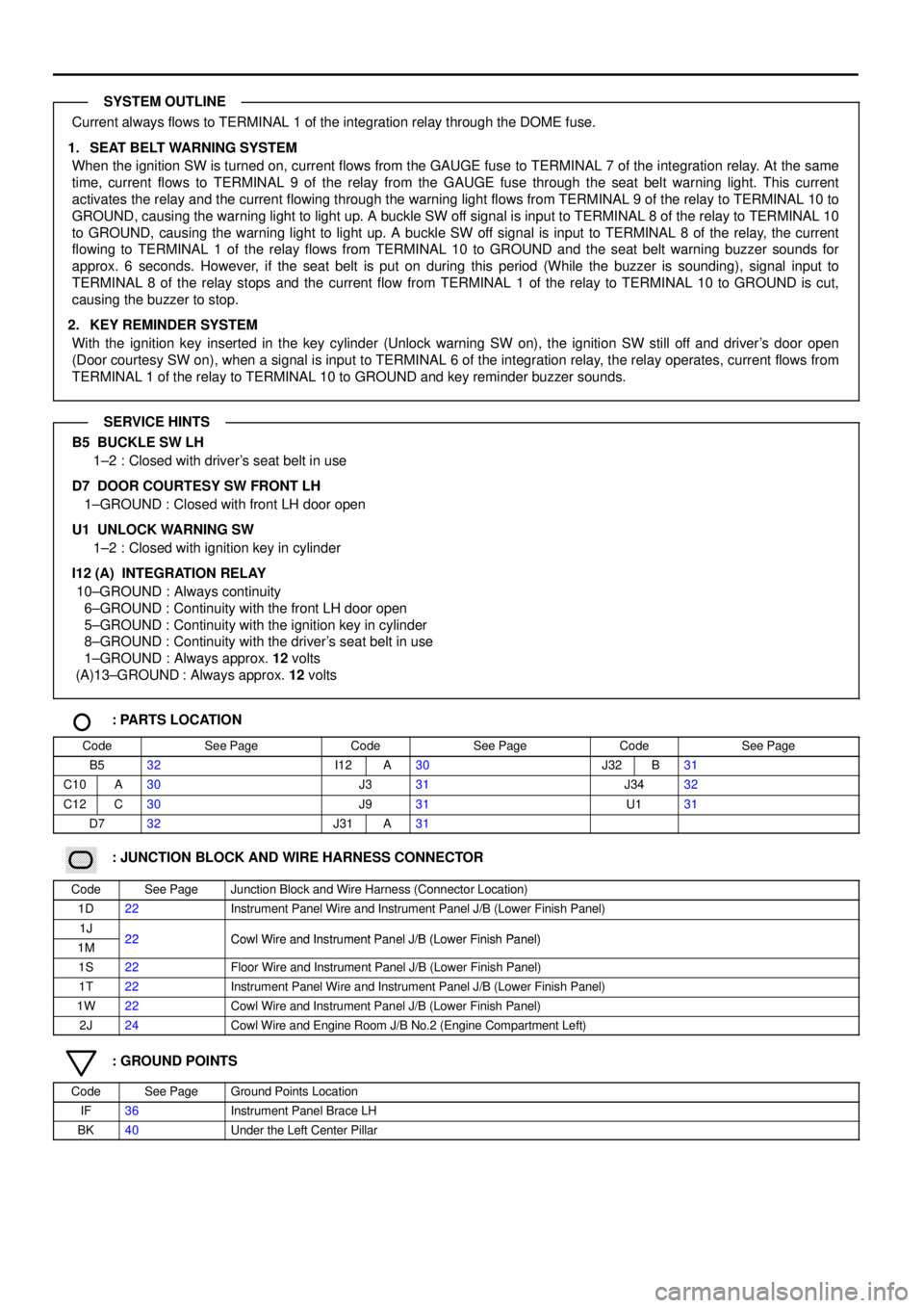
Current always flows to TERMINAL 1 of the integration relay through the DOME fuse.
1. SEAT BELT WARNING SYSTEM
When the ignition SW is turned on, current flows from the GAUGE fuse to TERMINAL 7 of the integration relay. At the same
time, current flows to TERMINAL 9 of the relay from the GAUGE fuse through the seat belt warning light. This current
activates the relay and the current flowing through the warning light flows from TERMINAL 9 of the relay to TERMINAL 10 to
GROUND, causing the warning light to light up. A buckle SW off signal is input to TERMINAL 8 of the relay to TERMINAL 10
to GROUND, causing the warning light to light up. A buckle SW off signal is input to TERMINAL 8 of the relay, the current
flowing to TERMINAL 1 of the relay flows from TERMINAL 10 to GROUND and the seat belt warning buzzer sounds for
approx. 6 seconds. However, if the seat belt is put on during this period (While the buzzer is sounding), signal input to
TERMINAL 8 of the relay stops and the current flow from TERMINAL 1 of the relay to TERMINAL 10 to GROUND is cut,
causing the buzzer to stop.
2. KEY REMINDER SYSTEM
With the ignition key inserted in the key cylinder (Unlock warning SW on), the ignition SW still off and driver's door open
(Door courtesy SW on), when a signal is input to TERMINAL 6 of the integration relay, the relay operates, current flows from
TERMINAL 1 of the relay to TERMINAL 10 to GROUND and key reminder buzzer sounds.
B5 BUCKLE SW LH
1±2 : Closed with driver's seat belt in use
D7 DOOR COURTESY SW FRONT LH
1±GROUND : Closed with front LH door open
U1 UNLOCK WARNING SW
1±2 : Closed with ignition key in cylinder
I12 (A) INTEGRATION RELAY
10±GROUND : Always continuity
6±GROUND : Continuity with the front LH door open
5±GROUND : Continuity with the ignition key in cylinder
8±GROUND : Continuity with the driver's seat belt in use
1±GROUND : Always approx. 12 volts
(A)13±GROUND : Always approx. 12 volts
: PARTS LOCATION
CodeSee PageCodeSee PageCodeSee Page
B532I12A30J32B31
C10A30J331J3432
C12C30J931U131
D732J31A31
������ ���: JUNCTION BLOCK AND WIRE HARNESS CONNECTOR
CodeSee PageJunction Block and Wire Harness (Connector Location)
1D22Instrument Panel Wire and Instrument Panel J/B (Lower Finish Panel)
1J22Cowl Wire and Instrument Panel J/B (Lower Finish Panel)1M22Cowl Wire and Instrument Panel J/B (Lower Finish Panel)
1S22Floor Wire and Instrument Panel J/B (Lower Finish Panel)
1T22Instrument Panel Wire and Instrument Panel J/B (Lower Finish Panel)
1W22Cowl Wire and Instrument Panel J/B (Lower Finish Panel)
2J24Cowl Wire and Engine Room J/B No.2 (Engine Compartment Left)
: GROUND POINTS
CodeSee PageGround Points Location
IF36Instrument Panel Brace LH
BK40Under the Left Center Pillar
SYSTEM OUTLINE
SERVICE HINTS
Page 4146 of 4592
5A
STARTER FROM POWER SOURCE SYSTEM (
SEE PAGE 44)
1J 3
IH1 5IC2 5 IE2 5IF117 IE23
IJ2 3B 2
B 5C10 A4C4C11 A3B7A12
EBB C
A B
IE1 6
11
IE1 7
2 1
IF
B±W Y±B Y±B
O O
R±W
R±L
P±L
Y±G P±L P±L W±B
Y±G
R±W R±W R±W
R±W W±B
B±W
PARK/NEUTRAL
POSITION SW P 1
OIL PRESSURE
SW O 1
WASHER LEVEL
WARNING SW W 1
JUNCTION
CONNECTOR J 1
BRAKE FLUID
LEVEL WARNING SW B 1
JUNCTION
CONNECTOR J 9
G±O
B
5
B 6
2B B
B
OI L
CRUISE
SEAT BELT
ABS
WASHER LEVEL
REAR LIGHTS
BRAKE
BULB
CHECK
RELAY
O/ D OFF
JUNCTION
CONNECTOR J22
P
N
A
TO CRUISE
CONTROL ECU
TO I NTEGRATION
RELAY
TO ABS ECU
TO LI GHT
FAI LURE
SENSOR
B±O
TO O/ D
MAIN SW
J 6
JUNCTION
CONNECTORB A, J 7
C10
COMBINATION METERB A, C11 C, C12
GR
IG211
IG210 B±W
GRGR
1
R±W
PARKING
BRAKE SW P 3
Page 4161 of 4592
I GROUND POINT
FRONT TURN SIGNAL
LIGHT AND PARKING
LIGHT LH
FRONT TURN SIGNAL
LIGHT AND PARKING
LIGHT RH
RADIATOR FAN
MOTOR
WASHER LEVEL
WARNING SW
WATER TEMP. SW
NO. 1
FAN NO. 2 RELAYABS SOL RELAY
FAN NO. 3 RELAY
HTR RELAY
ENGINE MAIN RELAY
EFI RELAY
FRONT WIPER MOTORABS ACTUATOR
1
1
1EA12
E 2 E 2
E 2
E 2
E 2
E 2
E 2
2J 10
2F4
2C 5
EB3
E 1
EA W±B W±B W±B W±B W±B
W± B
W±B
W±B
W±BW±B
W±B W± B W±B W±B W± B W±B W± B
W±B
W±B
W± B
W±B
W±B
W±B