Page 4017 of 4592

B HOW TO USE THIS MANUAL
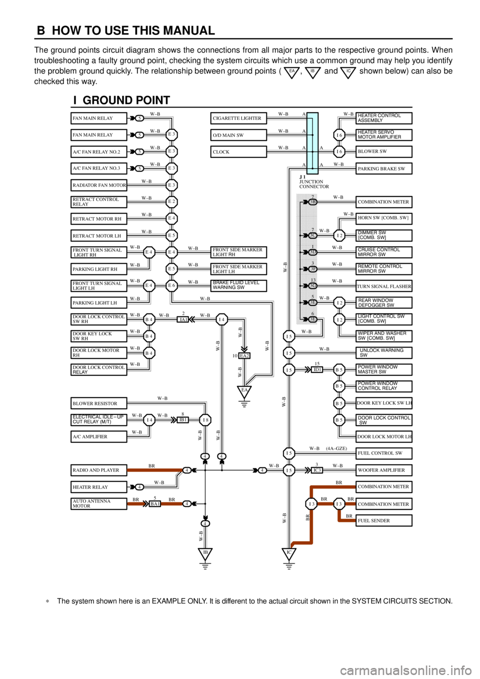
The ground points circuit diagram shows the connections from all major parts to the respective ground points. When
troubleshooting a faulty ground point, checking the system circuits which use a common ground may help you identify
the problem ground quickly. The relationship between ground points (
EA, IB and IC shown below) can also be
checked this way.
���� ���� ���� ���� ���� ���� ���� ���� ���� ���� ���� ���� ���� ���� ���� ���� ���� ���� ����
I GROUND POINT
FAN MAIN RELAY
FAN MAIN RELAY
A/C FAN RELAY NO.2
A/C FAN RELAY NO.3
RADIATOR FAN MOTOR
RETRACT CONTROL
RELAY
RETRACT MOTOR RH
RETRACT MOTOR LH
FRONT TURN SIGNAL
LIGHT RH
PARKING LIGHT RH
FRONT TURN SIGNAL
LIGHT LH
PARKING LIGHT LH
DOOR LOCK CONTROL
SW RH
DOOR KEY LOCK
SW RH
DOOR LOCK MOTOR
RH
BLOWER RESISTOR
A/C AMPLIFIER
RADIO AND PLAYER
HEATER RELAY
AUTO ANTENNA
MOTOR
BLOWER SW
PARKING BRAKE SW
COMBINATION METER
HORN SW [COMB. SW]
TURN SIGNAL FLASHER
DOOR KEY LOCK SW LH
DOOR LOCK MOTOR LH
FUEL CONTROL SW
WOOFER AMPLIFIER
COMBINATION METER
COMBINATION METER
FUEL SENDER
CIGARETTE LIGHTER
O/D MAIN SW
CLOCK
5
5
5
5
4
4
4
4
4BA15
IB18
EA2 10
3E5
3E
6 3G
13 3F
3 3D
1 3B
7
ID115
IC33
IA12
E 3
A
A AW±B
W±BW±B W±B
W±B W±B
W±B
W±B
W±B
W±B
W±B
W±B
W±B
W±B
W±B W±BW±B W±B W±B W±B
W±B W±B
W±BW±B
W±B
W±B
W±B W±B
W±B
BR
W±B
BR BRW±BW±B
W±B
W±B
W±B
W±B
W±B
W±B
W±B
W±B
W±B W±B
W±B
W±B
W±B
W±B
BR W±B
BR BR
BR W±B W±BW±B
W±BW±BBR W±B (4A±GZE)
W±B A A A
I 6
I 6
I 2
I 2
I 2
B 5I 5
I 5
I 5
B 5
B 5
B 5
I 5
I 5
I 3I 3
E 3
E 3
E 3
E 2
E 4
E 5
E 4
E 5
E 6E 4
E 4
B 4
EAI 4
B 4
B 4
I 4I 8
IBIC
3C7
4
JUNCTION
CONNECTOR J 1
4
DOOR LOCK CONTROL
RELAY
ELECTRICAL IDLE-UP
CUT RELAY (M/T)FRONT SIDE MARKER
LIGHT RH
FRONT SIDE MARKER
LIGHT LH
BRAKE FLUID LEVEL
WARNING SW
UNLOCK WARNING
SW WIPER AND WASHER
SW [COMB. SW] LIGHT CONTROL SW
[COMB. SW] HEATER CONTROL
ASSEMBLY
HEATER SERVO
MOTOR AMPLIFIER
DIMMER SW
[COMB. SW]
CRUISE CONTROL
MIRROR SW
REAR WINDOW
DEFOGGER SW
POWER WINDOW
MASTER SW
POWER WINDOW
CONTROL RELAY
DOOR LOCK CONTROL
SW
REMOTE CONTROL
MIRROR SW
*The system shown here is an EXAMPLE ONLY. It is different to the actual circuit shown in the SYSTEM CIRCUITS SECTION.
Page 4018 of 4592

B
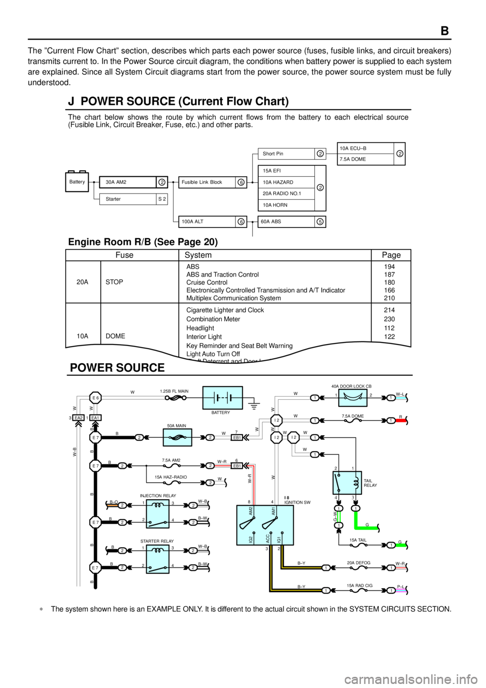
The ºCurrent Flow Chartº section, describes which parts each power source (fuses, fusible links, and circuit breakers)
transmits current to. In the Power Source circuit diagram, the conditions when battery power is supplied to each system
are explained. Since all System Circuit diagrams start from the power source, the power source system must be fully
understood.
Theft Deterrent and Door Lock Control
J POWER SOURCE (Current Flow Chart)
11
1
EA1 1EA2 3
7
EB16
E 6
E 7I 2I 2
I 2
E 7
E 7
E 7
2
1
1
2
2
2
2
2
B
B
W W
B B B B BW±B
B
B
B B±O
B±W
W±B
B±W STARTER RELAY INJECTION RELAY15A HAZ±RADIO7.5A AM250A MAIN 1.25B FL MAIN
BATTERY
WWW
W W W
R W±L
W
W
G±W
G
15A TAIL
20A DEFOG
15A RAD CIGTA I L
RELAY 7.5A DOME 40A DOOR LOCK CB
2 1
1 2
4 8
2 3
3 4
G
W±R
P±L B±Y
B±Y
W±R
AM2 IG2
ACC
IG1AM1W W
W±R
W W
W±B
21
1
1
1
1
2
2
2
2
3
4
3
4 1
2
1
22
1
11
1
IGNITION SW I 8
Battery
30A AM2
2
Starter S 220A RADIO NO.1
10A HORN
15A EFI
7.5A DOMEShort Pin
10A HAZARD
The chart below shows the route by which current flows from the battery to each electrical source
(Fusible Link, Circuit Breaker, Fuse, etc.) and other parts.
Engine Room R/B (See Page 20)
ABS
ABS and Traction Control
Cruise Control
Electronically Controlled Transmission and A/T Indicator
Multiplex Communication System
Cigarette Lighter and Clock
Key Reminder and Seat Belt Warning STOP
Fuse Page
194
214
11 2
System
DOME 20A
10ACombination Meter
Headlight
Interior Light
2
2
6 100A ALT
EB1
POWER SOURCE
Light Auto Turn Off187
180
166
210
230
122
10A ECU±B
5 60A ABS
2
6 Fusible Link Block2
*The system shown here is an EXAMPLE ONLY. It is different to the actual circuit shown in the SYSTEM CIRCUITS SECTION.
Page 4037 of 4592

G ELECTRICAL WIRING ROUTING
Position of Parts in Engine Compartment
A 1 A/C Condenser Fan Motor
A 2 A/C Magnetic Clutch and Lock Sensor
A 3 A/C Triple Pressure SW
(A/C Dual and Single Pressure SW)
A 4 ABS Actuator
A 5 ABS Actuator
A 6 ABS Speed Sensor Front LH
A 7 ABS Speed Sensor Front RH
A 8 Air Fuel Ratio Sensor
A 9 Airbag Sensor Front LH
A 10 Airbag Sensor Front RH
B 1 Brake Fluid Level Warning SW
C 1 Camshaft Position Sensor
C 2 Crankshaft Position Sensor
C 3 Cruise Control Actuator
D 1 Data Link Connector 1
E 1 Electronically Controlled Transmission Solenoid
E 2 Electronically Controlled Transmission Solenoid
E 3 Engine Coolant Temp. SensorF 1 Front Turn Signal Light and Parking Light LH
F 2 Front Turn Signal Light and Parking Light RH
F 3 Front Wiper Motor
F 4 Fuel Pressure Sensor (Delivery Pipe)
F 5 Fuel Pressure Sensor (Fuel Pipe)
F 6 Fuel Shutoff Valve (Delivery Pipe)
F 7 Fuel Shutoff Valve (Fuel Pressure Regulator)
F 8 Fuel Temp. Sensor (Delivery Pipe)
F 9 Fusible Link Block
F 10 Fusible Link Block
F 11 Fusible Link Block
F 12 Fusible Link Block
F 13 Fusible Link Block
F 14 Fusible Link Block
G 1 Generator
G 2 Generator
H 1 Headlight LH
H 2 Headlight RH
H 3 Horn (High)
H 4 Horn (Low)
Page 4038 of 4592
G
Position of Parts in Engine Compartment
I 1 Idle Air Control Valve
I 2 Ignition Coil and Igniter No.1
I 3 Ignition Coil and Igniter No.2
I 4 Injector No.1
I 5 Injector No.2
I 6 Injector No.3
I 7 Injector No.4
I 8 Intake Air Temp. Sensor
M 1 Manifold Absolute Pressure Sensor
N 1 Noise Filter (Ignition)
O 1 Oil Pressure SW
P 1 Park/Neutral Position SW,A/T Indicator Light SW and
Back±Up Light SW
P 2 Power Steering Oil Pressure SWR 1 Radiator Fan Motor
S 1 Starter
S 2 Starter
T 1 Throttle Position Sensor
V 1 Vehicle Speed Sensor (Combination Meter)
V 2 VSV (EGR)
W 1 Washer Level Warning SW
W 2 Washer Motor
W 3 Water Temp. Sender
W 4 Water Temp. SW No.1
Page 4040 of 4592

G
Position of Parts in Instrument Panel
J 1 Junction Connector
J 2 Junction Connector
J 3 Junction Connector
J 4 Junction Connector
J 5 Junction Connector
J 6 Junction Connector
J 7 Junction Connector
J 8 Junction Connector
J 9 Junction Connector
J 10 Junction Connector
J 11 Junction Connector
J 12 Junction Connector
J 13 Junction Connector
J 14 Junction Connector
J 15 Junction Connector
J 16 Junction Connector
J 17 Junction Connector
J 18 Junction Connector
J 19 Junction Connector
J 20 Junction Connector
J 21 Junction Connector
J 22 Junction Connector
J 23 Junction Connector
J 24 Junction Connector
J 25 Junction Connector
J 26 Junction ConnectorJ 27 Junction Connector
J 28 Junction Connector
J 29 Junction Connector
J 30 Junction Connector
J 31 Junction Connector
J 32 Junction Connector
K 1 Key Interlock Solenoid
O 2 O/D Main SW and A/T Shift Lever Illumination
P 3 Parking Brake SW
P 4 Power Outlet
R 2 Radio and Player
R 3 Radio and Player
R 4 Rear Window Defogger SW
R 5 Remote Control Mirror SW
R 6 Rheostat
S 3 Shift Lock ECU
S 4 Stop Light SW
T 2 Turn Signal Flasher
U 1 Unlock Warning SW
Page 4059 of 4592
CHARGING
SLIG B
IC REGULATOR 2A 11T 81J2
A 3A1A2B1 10A
GAUGE 5A
IGN
30A
AM2
B±G
YB±R B±G
B±G
B±G
BATTERY FL MAIN
3. 0W
YB 1
A 1
B A F 1
B±R
100A
ALTF 2C1A 13
B 4
IJ2 4 5A
ALT±S 2L 42C31K 31K1 2
74
6 AM2 AM1ACC
IG1
IG2
ST2
140A
AM1 1K 21K5
1B 11B5
E 3
B B±RB±R
WW±R W±RW
IGNITION SW I10B±RB±Y
Y
R±LR±L IE2 4 2
1
EB1 6
F10 , F 9 ,
G 1
GENERATORA B, G 2
C10
CHARGE WARNING LIGHT
[COMB. METER]B A, C11
F1 1
FUSIBLE LINK
BLOCKF C, F14
Page 4079 of 4592
TURN SIGNAL AND HAZARD WARNING LIGHT
1L 22K3
2 3
2 3
IF EB BMIE EB1 1 37956 231
5 5
A 66
A
A10 8
2
1FROM POWER SOURCE SYSTEM (
SEE PAGE 44)
OFF
ONRH
LH TURN HAZARD10A
HAZARD 7. 5A
TURN
G± R
W
G±RG± B
G±W
G± Y W±B
G±B
G±Y
W±BG±B
G±Y
W±BW± B W±B
HAZARD SWTURN SIGNA L SW
[COMB. SW]
REAR TURN SIGNAL LIGHT LH
[REAR COMB. LIGHT LH]FRONT TURN SI GNAL
LIGHT LH
REAR TURN SIGNAL LIGHT RH
[REAR COMB. LIGHT RH]
G± B
G± Y
TURN SIGNAL
FLASHER
FRONT TURN SI GNAL
LIGHT RH F 1
R 8
R10
F 2
J 4
J 9
H 5
JUNCTION
CONNECTOR
JUNCTION
CONNECTOR
LH RH
G± B G±B
G± B
G±Y W±B
E 2B 6
W± B W± B
W± B
B 1C1
B 161C 10 1A 5 1V 8
1H 6 1H 8 1A 2 1S 11 1S6
B BA B
G±BG± Y
CDD C
D
CJUNCTION
CONNECTOR J15 T 2C15
JUNCTION
CONNECTOR
TURN SIGNAL INDICATOR
LI GHT [COMB. METER]
G±Y G±B
G±Y
G±B
C C11 B , C12B J25 A , J26
Page 4082 of 4592

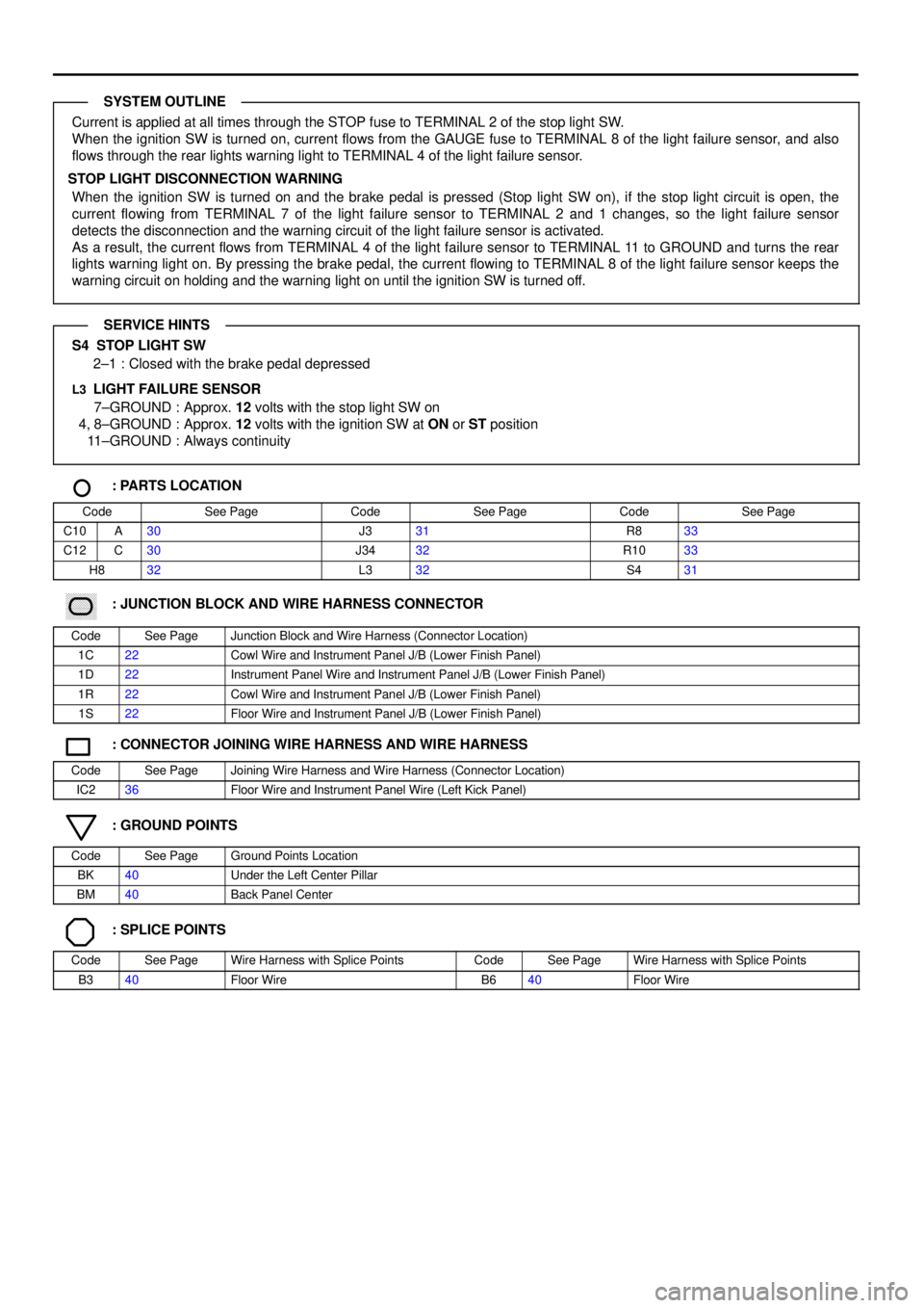
Current is applied at all times through the STOP fuse to TERMINAL 2 of the stop light SW.
When the ignition SW is turned on, current flows from the GAUGE fuse to TERMINAL 8 of the light failure sensor, and also
flows through the rear lights warning light to TERMINAL 4 of the light failure sensor.
STOP LIGHT DISCONNECTION WARNING
When the ignition SW is turned on and the brake pedal is pressed (Stop light SW on), if the stop light circuit is open, the
current flowing from TERMINAL 7 of the light failure sensor to TERMINAL 2 and 1 changes, so the light failure sensor
detects the disconnection and the warning circuit of the light failure sensor is activated.
As a result, the current flows from TERMINAL 4 of the light failure sensor to TERMINAL 11 to GROUND and turns the rear
lights warning light on. By pressing the brake pedal, the current flowing to TERMINAL 8 of the light failure sensor keeps the
warning circuit on holding and the warning light on until the ignition SW is turned off.
S4 STOP LIGHT SW
2±1 : Closed with the brake pedal depressed
L3 LIGHT FAILURE SENSOR
7±GROUND : Approx. 12 volts with the stop light SW on
4, 8±GROUND : Approx. 12 volts with the ignition SW at ON or ST position
11±GROUND : Always continuity
: PARTS LOCATION
CodeSee PageCodeSee PageCodeSee Page
C10A30J331R833
C12C30J3432R1033
H832L332S431
������ ���: JUNCTION BLOCK AND WIRE HARNESS CONNECTOR
CodeSee PageJunction Block and Wire Harness (Connector Location)
1C22Cowl Wire and Instrument Panel J/B (Lower Finish Panel)
1D22Instrument Panel Wire and Instrument Panel J/B (Lower Finish Panel)
1R22Cowl Wire and Instrument Panel J/B (Lower Finish Panel)
1S22Floor Wire and Instrument Panel J/B (Lower Finish Panel)
: CONNECTOR JOINING WIRE HARNESS AND WIRE HARNESS
CodeSee PageJoining Wire Harness and Wire Harness (Connector Location)
IC236Floor Wire and Instrument Panel Wire (Left Kick Panel)
: GROUND POINTS
CodeSee PageGround Points Location
BK40Under the Left Center Pillar
BM40Back Panel Center
: SPLICE POINTS
CodeSee PageWire Harness with Splice PointsCodeSee PageWire Harness with Splice Points
B340Floor WireB640Floor Wire
SYSTEM OUTLINE
SERVICE HINTS