Page 89 of 4592

AC0NJ±02
Z13472
Wire harness side: AC±88
± AIR CONDITIONINGAIR CONDITIONING AMPLIFIER
2570 Author�: Date�:
AIR CONDITIONING AMPLIFIER
ON±VEHICLE INSPECTION
1. REMOVE GLOVE COMPARTMENT
(See page BO±75)
2. INSPECT AMPLIFIER CIRCUIT
(a) Disconnect the amplifier connector and inspect the con-
nector on wire harness side, as shown in the chart below.
Test conditions:
�Ignition switch ON
�Blower speed switch HI
�Temperature control lever Max. Cool
Tester connectionConditionSpecified condition
5 ± GroundConstantContinuity
9 ± 13Evaporator temperature at 25°C (77°F)Approx. 1.5 kW
14 ± 13Constant65 ± 125 W at 25°C (77°F)
8 ± GroundA/C switch ONBattery positive voltage
8 ± GroundA/C switch OFFNo voltage
8 ± GroundMode switch DEF. positionBattery positive voltage
10 ± GroundA/C switch ONBelow 4.0 V
10 ± GroundA/C switch OFFNo voltage
If circuit is as specified, try replacing the amplifier with a new
one. If the circuit is not as specified, inspect the circuits con-
nected to other parts.
Page 90 of 4592
 Connect the connector to amplifier and inspect wire har-
ness side connector from the back side, as")
Z13473
From back side:
± AIR CONDITIONINGAIR CONDITIONING AMPLIFIER
AC±89
2571 Author�: Date�:
(b) Connect the connector to amplifier and inspect wire har-
ness side connector from the back side, as shown in the
chart below.
Test conditions:
�Running engine at idle speed
�Blower speed switch HI
�A/C switch ON
�Temperature control lever Max Cool
�Set on manifold gauge set
Tester connectionConditionSpecified condition
1 ± GroundMagnetic clutch is not engagedBelow 1.0 V
1 ± GroundMagnetic clutch is engagedNo voltage
7 ± GroundMagnetic clutch is not engagedBelow 1.0 V
7 ± GroundMagnetic clutch is engagedBattery positive voltage
2 ± GroundRefrigerant pressure 196 ± 1,340 kPaBattery positive voltage
2 ± GroundRefrigerant pressure
less than 196 or more than 3,140 kPaNo voltage
12 ± GroundRefrigerant pressure 196 ± 1,340 kPaBelow 1.0 V
12 ± GroundRefrigerant pressure
less than 196 or more than 3,140 kPaBattery positive voltage
12 ± GroundEngine coolant temp. 83°C (181°F) or belowBattery positive voltage
12 ± GroundEngine coolant temp. 93°C (199°F) or aboveBelow 1.0 V
If circuit is as specified, try replacing the amplifier with a new
one. If the circuit is not as specified, inspect the circuits con-
nected to other parts.
Page 91 of 4592
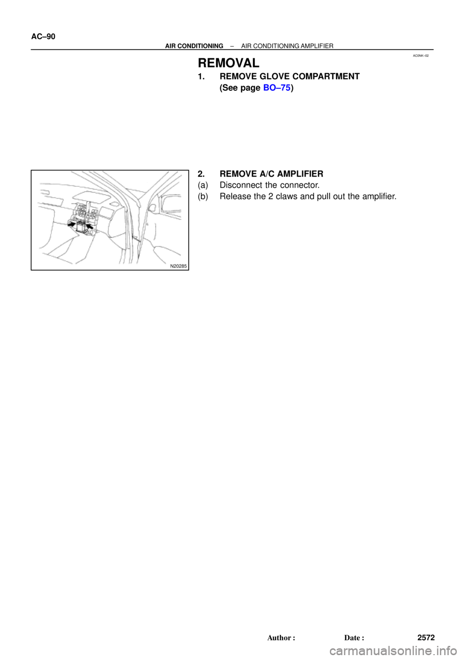
AC0NK±02
N20285
AC±90
± AIR CONDITIONINGAIR CONDITIONING AMPLIFIER
2572 Author�: Date�:
REMOVAL
1. REMOVE GLOVE COMPARTMENT
(See page BO±75)
2. REMOVE A/C AMPLIFIER
(a) Disconnect the connector.
(b) Release the 2 claws and pull out the amplifier.
Page 92 of 4592
AC0NL±01
± AIR CONDITIONINGAIR CONDITIONING AMPLIFIER
AC±91
2573 Author�: Date�:
INSTALLATION
Installation is in the reverse order of removal (See page AC±90).
Page 93 of 4592
 SWITCH
2574 Author�: Date�:
ENGINE COOLANT")
AC227±01
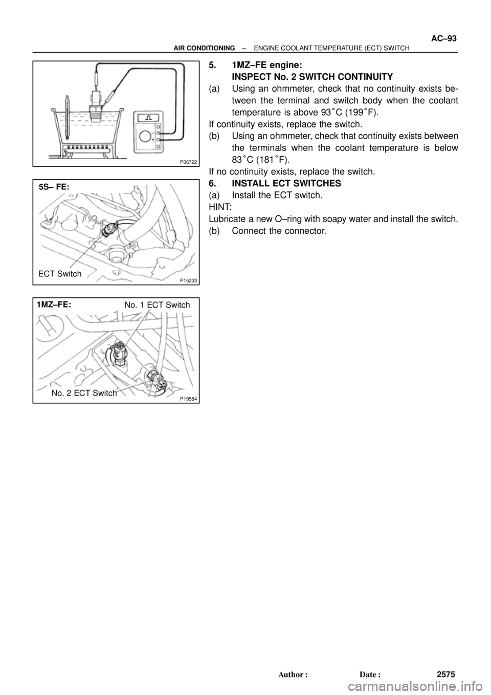
P15233
5S±FE:
ECT Switch
P19584
1MZ±FE:No. 1 ECT Switch
No. 2 ECT Switch
P01924
P01924
AC±92
± AIR CONDITIONINGENGINE COOLANT TEMPERATURE (ECT) SWITCH
2574 Author�: Date�:
ENGINE COOLANT
TEMPERATURE (ECT) SWITCH
INSPECTION
1. DRAIN ENGINE COOLANT FROM RADIATOR
HINT:
It is not necessary to drain out all the coolant.
2. REMOVE ECT SWITCHES
(a) Disconnect the connector.
(b) Remove the ECT switch.
3. 5S±FE engine:
INSPECT ECT SWITCH CONTINUITY
(a) Using an ohmmeter, check that no continuity exists be-
tween the terminals when the coolant temperature is
above 93°C (199°F).
If continuity exists, replace the switch.
(b) Using an ohmmeter, check that continuity exists between
the terminals when the coolant temperature is below
83°C (181°F).
If no continuity exists, replace the switch.
4. 1MZ±FE engine:
INSPECT No. 1 SWITCH CONTINUITY
(a) Using an ohmmeter, check that no continuity exists be-
tween the terminals when the coolant temperature is
above 98°C (208°F).
If continuity exists, replace the switch.
(b) Using an ohmmeter, check that continuity exists between
the terminals when the coolant temperature is below
88°C (190°F).
If no continuity exists, replace the switch.
Page 94 of 4592
P06722
P15233
5S± FE:
ECT Switch
P19584
1MZ±FE:
No. 1 ECT Switch
No. 2 ECT Switch
± AIR CONDITIONINGENGINE COOLANT TEMPERATURE (ECT) SWITCH
AC±93
2575 Author�: Date�:
5. 1MZ±FE engine:
INSPECT No. 2 SWITCH CONTINUITY
(a) Using an ohmmeter, check that no continuity exists be-
tween the terminal and switch body when the coolant
temperature is above 93°C (199°F).
If continuity exists, replace the switch.
(b) Using an ohmmeter, check that continuity exists between
the terminals when the coolant temperature is below
83°C (181°F).
If no continuity exists, replace the switch.
6. INSTALL ECT SWITCHES
(a) Install the ECT switch.
HINT:
Lubricate a new O±ring with soapy water and install the switch.
(b) Connect the connector.
Page 158 of 4592

INTRODUCTIONGLOSSARY OF SAE AND TOYOTA TERMS ±
IN±6
GLOSSARY OF SAE AND TOYOTA TERMS
This glossary lists all SAE±J1930 terms and abbreviations used in this manual in compliance with SAE
recommendations, as well as their Toyota equivalents.
SAE
ABBREVIATIONSSAE TERMSTOYOTA TERMS
( )±±ABBREVIATIONS
A/CAir ConditioningAir Conditioner
ACLAir CleanerAir Cleaner
AIRSecondary Air InjectionAir Injection (AI)
APAccelerator Pedal±
B+Battery Positive Voltage+B, Battery Voltage
BAROBarometric Pressure±
CACCharge Air CoolerIntercooler
CARBCarburetorCarburetor
CFIContinuous Fuel Injection±
CKPCrankshaft PositionCrank Angle
CLClosed LoopClosed Loop
CMPCamshaft PositionCam Angle
CPPClutch Pedal Position±
CTOXContinuous Trap Oxidizer±
CTPClosed Throttle Position±
DFIDirect Fuel Injection (Diesel)Direct Injection (DI)
DIDistributor Ignition±
DLC1
DLC2
DLC3Data Link Connector 1
Data Link Connector 2
Data Link Connector 31: Check Connector
2: Toyota Diagnosis Communication Link (TDCL)
3: OBD@@@@@: [g 2] Diagnostic Connector
DTCDiagnostic Trouble CodeDiagnostic Code
DTMDiagnostic Test Mode±
ECLEngine Control Level±
ECMEngine Control ModuleEngine ECU (Electronic Control Unit)
ECTEngine Coolant TemperatureCoolant Temperature, Water Temperature (THW)
EEPROMElectrically Erasable Programmable Read Only
MemoryElectrically Erasable Programmable Read Only Memory
(EEPROM),
Erasable Programmable Read Only Memory(EPROM)
EFEEarly Fuel EvaporationCold Mixture Heater (CMH), Heat Control Valve (HCV)
EGRExhaust Gas RecirculationExhaust Gas Recirculation (EGR)
EIElectronic IgnitionToyota Distributorless Ignition (TDI)
EMEngine ModificationEngine Modification (EM)
EPROMErasable Programmable Read Only MemoryProgrammable Read Only Memory (PROM)
EVAPEvaporative EmissionEvaporative Emission Control (EVAP)
FCFan Control±
FEEPROMFlash Electrically Erasable Programmable
Read Only Memory±
FEPROMFlash Erasable Programmable Read Only Memory±
FFFlexible Fuel±
FPFuel PumpFuel Pump
GENGeneratorAlternator
GNDGroundGround (GND)
HO2SHeated Oxygen SensorHeated Oxygen Sensor (HO2S)
IN016±02
Page 301 of 4592

INTRODUCTIONGLOSSARY OF SAE AND TOYOTA TERMS ±
IN±6
GLOSSARY OF SAE AND TOYOTA TERMS
This glossary lists all SAE±J1930 terms and abbreviations used in this manual in compliance with SAE
recommendations, as well as their Toyota equivalents.
SAE
ABBREVIATIONSSAE TERMSTOYOTA TERMS
( )±±ABBREVIATIONS
A/CAir ConditioningAir Conditioner
ACLAir CleanerAir Cleaner
AIRSecondary Air InjectionAir Injection (AI)
APAccelerator Pedal±
B+Battery Positive Voltage+B, Battery Voltage
BAROBarometric Pressure±
CACCharge Air CoolerIntercooler
CARBCarburetorCarburetor
CFIContinuous Fuel Injection±
CKPCrankshaft PositionCrank Angle
CLClosed LoopClosed Loop
CMPCamshaft PositionCam Angle
CPPClutch Pedal Position±
CTOXContinuous Trap Oxidizer±
CTPClosed Throttle Position±
DFIDirect Fuel Injection (Diesel)Direct Injection (DI)
DIDistributor Ignition±
DLC1
DLC2
DLC3Data Link Connector 1
Data Link Connector 2
Data Link Connector 31: Check Connector
2: Toyota Diagnosis Communication Link (TDCL)
3: OBD@@@@@: [g 2] Diagnostic Connector
DTCDiagnostic Trouble CodeDiagnostic Code
DTMDiagnostic Test Mode±
ECLEngine Control Level±
ECMEngine Control ModuleEngine ECU (Electronic Control Unit)
ECTEngine Coolant TemperatureCoolant Temperature, Water Temperature (THW)
EEPROMElectrically Erasable Programmable Read Only
MemoryElectrically Erasable Programmable Read Only Memory
(EEPROM),
Erasable Programmable Read Only Memory(EPROM)
EFEEarly Fuel EvaporationCold Mixture Heater (CMH), Heat Control Valve (HCV)
EGRExhaust Gas RecirculationExhaust Gas Recirculation (EGR)
EIElectronic IgnitionToyota Distributorless Ignition (TDI)
EMEngine ModificationEngine Modification (EM)
EPROMErasable Programmable Read Only MemoryProgrammable Read Only Memory (PROM)
EVAPEvaporative EmissionEvaporative Emission Control (EVAP)
FCFan Control±
FEEPROMFlash Electrically Erasable Programmable
Read Only Memory±
FEPROMFlash Erasable Programmable Read Only Memory±
FFFlexible Fuel±
FPFuel PumpFuel Pump
GENGeneratorAlternator
GNDGroundGround (GND)
HO2SHeated Oxygen SensorHeated Oxygen Sensor (HO2S)
IN016±02