1999 TOYOTA CAMRY air conditioning
[x] Cancel search: air conditioningPage 4000 of 4592
Toyota Supports ASE CertificationPage 1 of 2
AC003-04Title:
A/C COMPRESSOR INSTALLATION
PROCEDURE
Models:
Applicable Models
Technical Service
BULLETIN
March 1, 2004
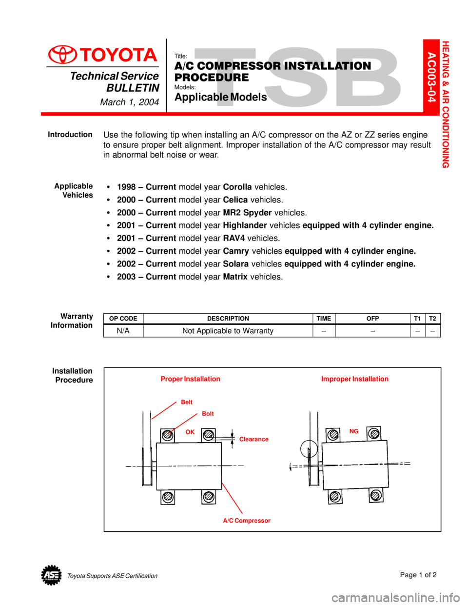
Use the following tip when installing an A/C compressor on the AZ or ZZ series engine
to ensure proper belt alignment. Improper installation of the A/C compressor may result
in abnormal belt noise or wear.
�1998 ± Current model year Corolla vehicles.
�2000 ± Current model year Celica vehicles.
�2000 ± Current model year MR2 Spyder vehicles.
�2001 ± Current model year Highlander vehicles equipped with 4 cylinder engine.
�2001 ± Current model year RAV4 vehicles.
�2002 ± Current model year Camry vehicles equipped with 4 cylinder engine.
�2002 ± Current model year Solara vehicles equipped with 4 cylinder engine.
�2003 ± Current model year Matrix vehicles.
OP CODEDESCRIPTIONTIMEOFPT1T2
N/ANot Applicable to Warranty±±±±
Belt
Bolt
Clearance
A/C CompressorOKNG
Proper Installation Improper Installation
HEATING & AIR CONDITIONING
Introduction
Applicable
Vehicles
Warranty
Information
Installation
Procedure
Page 4026 of 4592

*The titles given inside the components are the names of the terminals (terminal codes) and are not treated as being
abbreviations.
ABBREVIATIONS D
ABBREVIATIONS
The following abbreviations are used in this manual.
ABS = Anti±Lock Brake System
A/C = Air Conditioning
A/T = Automatic Transaxle
COMB. = Combination
ECU = Electronic Control Unit
EGR = Exhaust Gas Recirculation
ESA = Electronic Spark Advance
EVAP = Evaporative Emission
FL = Fusible Link
IAC = Idle Air Control
J/B = Junction Block
LH = Left±Hand
O/D = Overdrive
R/B = Relay Block
RH = Right±Hand
SFI = Sequential Multiport Fuel Injection
SRS = Supplemental Restraint System
SW = Switch
TEMP. = Temperature
VSV = Vacuum Switching Valve
w/ = With
w/o = Without
Page 4069 of 4592

ENGINE CONTROL
2. CONTROL SYSTEM
*SFI system
The SFI system monitors the engine condition through the signals, which are input from each sensor to the engine
control module. The best fuel injection volume is decided based on this data and the program memorized by the engine
control module, and the control signal is output to TERMINALS #10+, #20+, #30+ and #40+ of the engine control
module to operate the injector. (Inject the fuel). The SFI system produces control of fuel injection operation by the engine
control module in response to the driving conditions.
*ESA system
The ESA system monitors the engine condition through the signals, which are input to the engine control module from
each sensor the best ignition timing is detected according to this data and the memorized data in the engine control
module, and the control signal is output to TERMINALS IGT1 and IGT2. This signal controls the igniter to provide the
best ignition timing for the driving conditions.
*IAC system
The IAC system (Step motor type) increases the RPM and provides idling stability for fast idle±up when the engine is
cold and when the idle speed has dropped due to electrical load, etc. The engine control module evaluates the signals
from each sensor, outputs current to TERMINAL RSD , and controls the idle air control valve.
*Fuel control system
The engine control module operation outputs to TERMINAL FC and controls the CIR OPN relay. Thus controls the fuel
shutoff valve open and close.
*EGR control system
The EGR control system controls the VSV (EGR) by evaluating the signals from each sensor which are input to the
engine control module and by sending output to TERMINAL EGR of the engine control module.
*A/C conditioning operation system
In addition to the conventional A/C cut control, the engine control module performs the air conditioning operation as well
since the A/C amplifier function is built in it.
3. DIAGNOSIS SYSTEM
With the diagnosis system, when there is a malfunctioning in the engine control module signal system, the malfunction
system is recorded in the memory. The malfunctioning system can then be found by reading the display (Code) of the
malfunction indicator lamp.
4. FAIL±SAFE SYSTEM
When a malfunction occurs in any system, if there is a possibility of engine trouble being caused by continued control based
on the signals from that system, the fail±safe system either controls the system by using data (Standard values) recorded in
the engine control module memory or else stops the engine.
E4 (A), E5 (B), E6 (C), E7 (D) ENGINE CONTROL MODULE
BATT±E1 : Always 9.0±14.0 volts
+B±E1 :9.0±14.0 volts with the ignition SW at ON or ST position
VC±E2 :4.5± 5.5 volts with the ignition SW on
VTA±E2 :0.3± 0.8 volts with the ignition SW on and throttle valve fully closed
3.2±4.9 volts with the ignition SW on and throttle valve open
PIM±E2 :3.3± 3.9 volts with the ignition SW on
THA±E2 :0.5±3.4 volts with the ignition SW on and intake air temp. 20°C (68°F)
THW±E2 :0.2± 1.0 volts with the ignition SW on and coolant temp. 80°C (176°F)
STA±E1 :6.0±14.0 volts with the engine cranking
W±E1 :9.0±14.0 volts with the no trouble and engine running
TE1±E1 :9.0±14.0 volts with the ignition SW on
NSW±E1 :0± 3.0 volts with the ignition SW on and Park/Neutral position SW position P or N position
9.0±14.0 volts with the ignition SW on and except Park/Neutral position SW position P or N position
IGT1, IGT2±E1 : Pulse generation with the engine cranking or idling
#10+, #20+, #30+, #40+±E01, E02 :9.0±14.0 volts with the ignition SW on
SERVICE HINTS
Page 4155 of 4592
AIR CONDITIONING
1 1
11 1
12
3584
IF EB215
4
23
1 HI M2 M11W 2
I 6L±B
B±W
L±B
B±WL±W W±B
W±BL±R W±B
L±W
10A
HEATER
1
HTR
RELAY
BLOWER RESISTOR
BLOWER
MOTOR
B±W
L±B
L±O
BLOWER SWOFF FROM POWER SOURCE SYSTEM (
SEE PAGE 44)
LO B 2B 3
B 412
1 1 EB131R 3
2C 92K 5
23 1511
11A
AAA
3
JUNCTION
CONNECTOR J 9JUNCTION
CONNECTOR J30 FUSIBLE
LINK BLOCK F13
L±R
L±B L±B
L±B L±B
B±WL±Y B±W
L±B
L±B L±B
L±RTO FAN NO. 3 RELAY MG CLT
RELAY
10A A/C
EB2 1EB12
L±R
W±B
L±B
W± B
W±BL±B W±BL±RL±Y B±WL±B
W±B
50A HTR
A
I 3 W±B 61 M
Page 4157 of 4592
AIR CONDITIONING
A/C EVAPORATOR
TEMP. SENSOR A11
EC IG2 3 IG2 1IG3 6 IG3 10IJ2 9IJ210
C 18 B 9 B 10 A 10 A21 D10 A 151
4
IJ2 2
B
A2 1
B4
A A/C MAGNETIC
CLUTCH AND
LOCK SENSOR A 2
A/C DUAL
PRESSURE SW A 3
ENGINE CONTROL MODULE L±B
B±W
G
B±W
R±B
R±B
R±W1
2
L±W
BR L±R
BR
W±L
LOCK PRSMGC A/CS THR E2 LOCK IN
BR BRW±L
BRW± L
BR R±B
L±Y
GB E 4 A , E 5 C, E 6 IG1 1B B
JUNCTION
CONNECTOR J 7
JUNCTION
CONNECTOR J20 BJUNCTION
CONNECTOR J12
G
L±Y
BR
D , E 7
Page 4158 of 4592
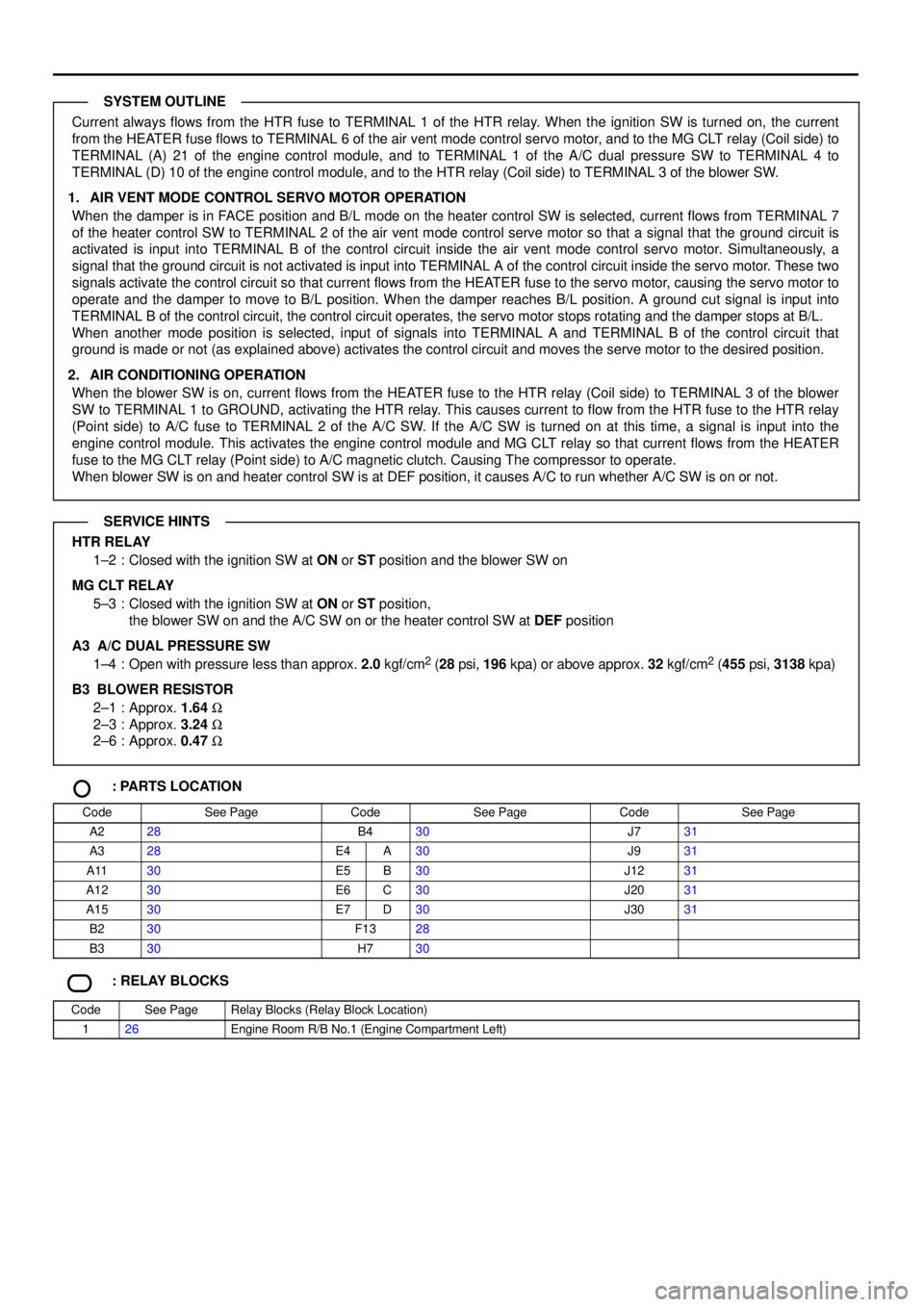
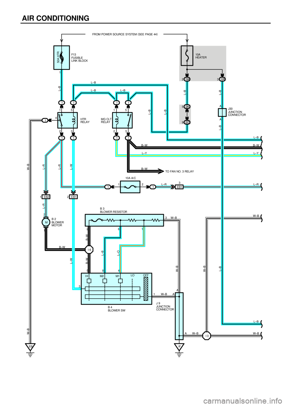
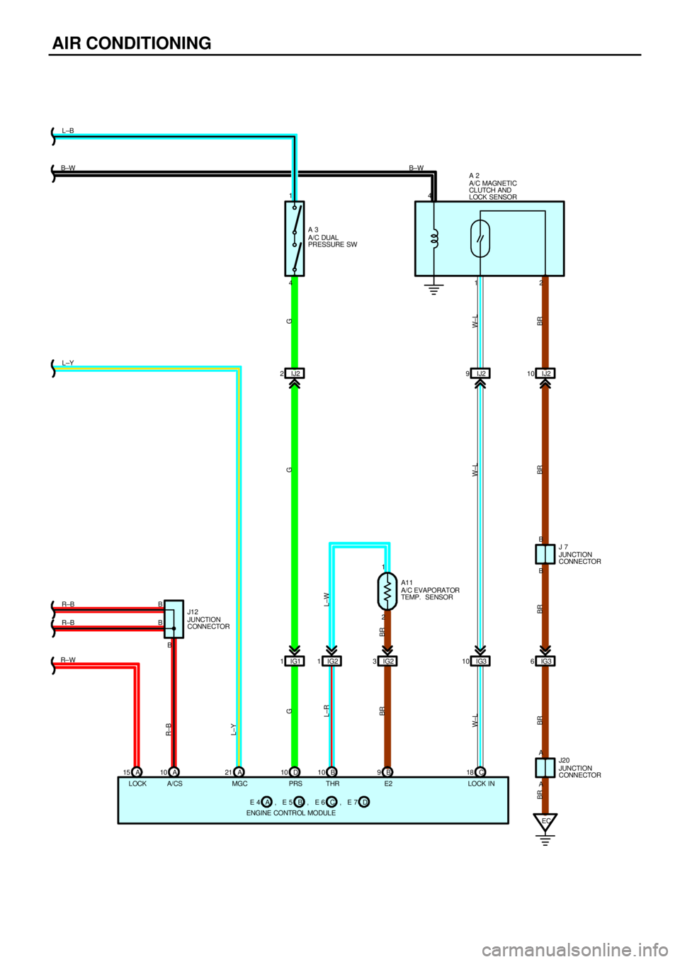
Current always flows from the HTR fuse to TERMINAL 1 of the HTR relay. When the ignition SW is turned on, the current
from the HEATER fuse flows to TERMINAL 6 of the air vent mode control servo motor, and to the MG CLT relay (Coil side) to
TERMINAL (A) 21 of the engine control module, and to TERMINAL 1 of the A/C dual pressure SW to TERMINAL 4 to
TERMINAL (D) 10 of the engine control module, and to the HTR relay (Coil side) to TERMINAL 3 of the blower SW.
1. AIR VENT MODE CONTROL SERVO MOTOR OPERATION
When the damper is in FACE position and B/L mode on the heater control SW is selected, current flows from TERMINAL 7
of the heater control SW to TERMINAL 2 of the air vent mode control serve motor so that a signal that the ground circuit is
activated is input into TERMINAL B of the control circuit inside the air vent mode control servo motor. Simultaneously, a
signal that the ground circuit is not activated is input into TERMINAL A of the control circuit inside the servo motor. These two
signals activate the control circuit so that current flows from the HEATER fuse to the servo motor, causing the servo motor to
operate and the damper to move to B/L position. When the damper reaches B/L position. A ground cut signal is input into
TERMINAL B of the control circuit, the control circuit operates, the servo motor stops rotating and the damper stops at B/L.
When another mode position is selected, input of signals into TERMINAL A and TERMINAL B of the control circuit that
ground is made or not (as explained above) activates the control circuit and moves the serve motor to the desired position.
2. AIR CONDITIONING OPERATION
When the blower SW is on, current flows from the HEATER fuse to the HTR relay (Coil side) to TERMINAL 3 of the blower
SW to TERMINAL 1 to GROUND, activating the HTR relay. This causes current to flow from the HTR fuse to the HTR relay
(Point side) to A/C fuse to TERMINAL 2 of the A/C SW. If the A/C SW is turned on at this time, a signal is input into the
engine control module. This activates the engine control module and MG CLT relay so that current flows from the HEATER
fuse to the MG CLT relay (Point side) to A/C magnetic clutch. Causing The compressor to operate.
When blower SW is on and heater control SW is at DEF position, it causes A/C to run whether A/C SW is on or not.
HTR RELAY
1±2 : Closed with the ignition SW at ON or ST position and the blower SW on
MG CLT RELAY
5±3 : Closed with the ignition SW at ON or ST position,
the blower SW on and the A/C SW on or the heater control SW at DEF position
A3 A/C DUAL PRESSURE SW
1±4 : Open with pressure less than approx. 2.0 kgf/cm
2 (28 psi, 196 kpa) or above approx. 32 kgf/cm2 (455 psi, 3138 kpa)
B3
BLOWER RESISTOR
2±1 : Approx. 1.64 W
2±3 : Approx. 3.24 W
2±6 : Approx. 0.47 W
: PARTS LOCATION
CodeSee PageCodeSee PageCodeSee Page
A228B430J731
A328E4A30J931
A1130E5B30J1231
A1230E6C30J2031
A1530E7D30J3031
B230F1328
B330H730
: RELAY BLOCKS
CodeSee PageRelay Blocks (Relay Block Location)
126Engine Room R/B No.1 (Engine Compartment Left)
SYSTEM OUTLINE
SERVICE HINTS
Page 4159 of 4592
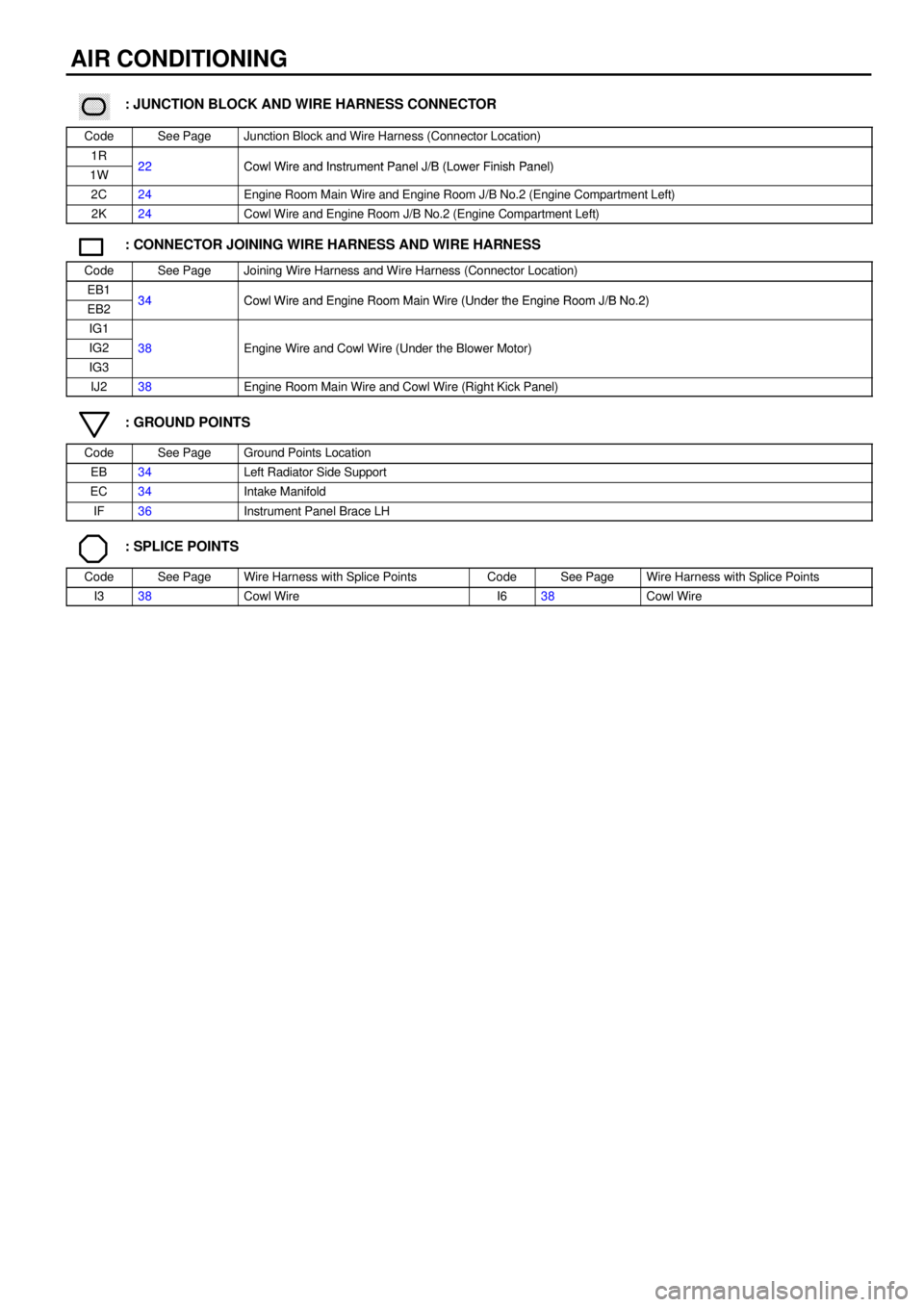
AIR CONDITIONING
������ ���: JUNCTION BLOCK AND WIRE HARNESS CONNECTOR
CodeSee PageJunction Block and Wire Harness (Connector Location)
1R22Cowl Wire and Instrument Panel J/B (Lower Finish Panel)1W22Cowl Wire and Instrument Panel J/B (Lower Finish Panel)
2C24Engine Room Main Wire and Engine Room J/B No.2 (Engine Compartment Left)
2K24Cowl Wire and Engine Room J/B No.2 (Engine Compartment Left)
: CONNECTOR JOINING WIRE HARNESS AND WIRE HARNESS
CodeSee PageJoining Wire Harness and Wire Harness (Connector Location)
EB134Cowl Wire and Engine Room Main Wire (Under the Engine Room J/B No 2)EB234Cowl Wire and Engine Room Main Wire (Under the Engine Room J/B No.2)
IG1
IG238Engine Wire and Cowl Wire (Under the Blower Motor)
IG3
g()
IJ238Engine Room Main Wire and Cowl Wire (Right Kick Panel)
: GROUND POINTS
CodeSee PageGround Points Location
EB34Left Radiator Side Support
EC34Intake Manifold
IF36Instrument Panel Brace LH
: SPLICE POINTS
CodeSee PageWire Harness with Splice PointsCodeSee PageWire Harness with Splice Points
I338Cowl WireI638Cowl Wire
Page 4169 of 4592

J POWER SOURCE (Current Flow Chart)
Instrument Panel J/B (See Page 22)
FuseSystemPage
5AIGN
Charging
Combination Meter
Electronically Controlled Transmission and A/T Indicator
Engine Control
SRS52
138
102
54
11 7
5ASTARTER
Combination Meter
Electronically Controlled Transmission and A/T Indicator
Engine Control
Starting and Ignition138
102
54
48
7.5AOBDEngine Control54
7.5APANEL
Cigarette Lighter and Clock
Combination Meter
Illumination126
138
80
7.5ARAD±NO.2Radio and Player136
7.5ATURNTurn Signal and Hazard Warning Light72
10AGAUGE
ABS
Back±Up Light
Charging
Combination Meter
Cruise Control
Door Lock Control
Electronically Controlled Transmission and A/T Indicator
Engine Control
Key Reminder and Seat Belt Warning
Light Auto Turn Off
Power Window
Stop Light
Taillight11 2
88
52
138
108
98
102
54
128
68
94
74
84
10AHEATERAir Conditioning
Rear Window Defogger and Mirror Heater148
134
10AMIRROR±HEATEREngine Control
Rear Window Defogger and Mirror Heater54
134
10ATAILEngine Control
Taillight54
84
15ACIG
Cigarette Lighter and Clock
Remote Control Mirror
Shift Lock
SRS126
132
122
11 7
15AECU±IG
ABS
Cruise Control
Radiator Fan and Condenser Fan
Shift Lock11 2
108
144
122
*These are the page numbers of the first page on which the related system is shown.