1999 TOYOTA CAMRY air conditioning
[x] Cancel search: air conditioningPage 4171 of 4592

J POWER SOURCE (Current Flow Chart)
FuseSystemPage
40AMAIN
Headlight
Light Auto Turn Off
Starting and Ignition124
11 7
72
Engine Room R/B No.1 (See Page 26)
FuseSystemPage
10AA/CAir Conditioning148
Engine Room R/B No.3 (See Page 26)
FuseSystemPage
60AFL ABSABS11 2
Fusible Link Block (F8 on See Page 27)
FuseSystemPage
50AHTRAir Conditioning148
100AALT
Charging
Illumination
Light Auto Turn Off
Radiator Fan and Condenser Fan
Taillight52
80
68
144
84
*These are the page numbers of the first page on which the related system is shown.
Page 4187 of 4592

SYSTEM INDEX
M OVERALL ELECTRICAL WIRING DIAGRAM
SYSTEMS LOCATION SYSTEMS LOCATION
ABS 15±2. . . . . . . . . . . . . . . . . . . . . . . . . . . . . . . . . . . . . . . . . . . . . . . . . . . . .
Air Conditioning 19±2. . . . . . . . . . . . . . . . . . . . . . . . . . . . . . . . . . . . . . . . . . .
Back±Up Light 5±4. . . . . . . . . . . . . . . . . . . . . . . . . . . . . . . . . . . . . . . . . . . . . .
Charging 1±4. . . . . . . . . . . . . . . . . . . . . . . . . . . . . . . . . . . . . . . . . . . . . . . . . . .
Cigarette Lighter and Clock 12±4. . . . . . . . . . . . . . . . . . . . . . . . . . . . . . . . .
Combination Meter 17±2. . . . . . . . . . . . . . . . . . . . . . . . . . . . . . . . . . . . . . . .
Cruse Control 13±2. . . . . . . . . . . . . . . . . . . . . . . . . . . . . . . . . . . . . . . . . . . . .
Door Lock Control 11±2. . . . . . . . . . . . . . . . . . . . . . . . . . . . . . . . . . . . . . . . . .
Electronically Controlled Transmission and A/T Indicator 3±2. . . . . . . . . .
Engine Control 2±2. . . . . . . . . . . . . . . . . . . . . . . . . . . . . . . . . . . . . . . . . . . . . .
Headlight 4±2. . . . . . . . . . . . . . . . . . . . . . . . . . . . . . . . . . . . . . . . . . . . . . . . . . .
Horn 16±4. . . . . . . . . . . . . . . . . . . . . . . . . . . . . . . . . . . . . . . . . . . . . . . . . . . . .
Illumination 7±2. . . . . . . . . . . . . . . . . . . . . . . . . . . . . . . . . . . . . . . . . . . . . . . . .
Interior Light 6±3. . . . . . . . . . . . . . . . . . . . . . . . . . . . . . . . . . . . . . . . . . . . . . . .
Key Reminder and Seat Belt Warning 16±2. . . . . . . . . . . . . . . . . . . . . . . .
Light Auto Turn Off 6±2. . . . . . . . . . . . . . . . . . . . . . . . . . . . . . . . . . . . . . . . . . Power Outlet 12±3. . . . . . . . . . . . . . . . . . . . . . . . . . . . . . . . . . . . . . . . . . . . . .
Power Source 1~19±1. . . . . . . . . . . . . . . . . . . . . . . . . . . . . . . . . . . . . . . . . . .
Power Window 10±2. . . . . . . . . . . . . . . . . . . . . . . . . . . . . . . . . . . . . . . . . . . .
Radiator Fan and Condenser Fan 18±3. . . . . . . . . . . . . . . . . . . . . . . . . . . .
Radio and Player 11±7. . . . . . . . . . . . . . . . . . . . . . . . . . . . . . . . . . . . . . . . . . .
Rear Window Defogger and Mirror Heater 18±2. . . . . . . . . . . . . . . . . . . .
Remote Control Mirror 9±3. . . . . . . . . . . . . . . . . . . . . . . . . . . . . . . . . . . . . . . .
Shift Lock 12±2. . . . . . . . . . . . . . . . . . . . . . . . . . . . . . . . . . . . . . . . . . . . . . . .
SRS 14±2. . . . . . . . . . . . . . . . . . . . . . . . . . . . . . . . . . . . . . . . . . . . . . . . . . . . .
Starting and Ignition 1±2. . . . . . . . . . . . . . . . . . . . . . . . . . . . . . . . . . . . . . . . . .
Stop Light 8±4. . . . . . . . . . . . . . . . . . . . . . . . . . . . . . . . . . . . . . . . . . . . . . . . . .
Taillight 8±2. . . . . . . . . . . . . . . . . . . . . . . . . . . . . . . . . . . . . . . . . . . . . . . . . . . . .
Turn Signal and Hazard Warning Light 5±2. . . . . . . . . . . . . . . . . . . . . . . . . .
Wiper and Washer 9±2. . . . . . . . . . . . . . . . . . . . . . . . . . . . . . . . . . . . . . . . . . .
Page 4227 of 4592

1
234
1
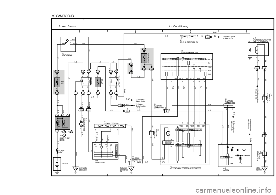
19 CAMRY CNG
1
1F 2F 1E1
100A ALT 50A HTR1B 12K
5
3 1K
1
2 4
B±Y AM1 IG1ACC
2
I10
IGNITION SW
2
1
EBLeft r adiator
side support51
2 1
3 5
41
8 1
10A A/C
11
1 15
1 EB2
HT R REL A Y
2EB1
1 2
M1
L±R2C 9
MG CLT RELAY 10A HEATER
1W 231R1K 1
1L±B
6
HI M2 M1
LO OFF 2
3
IF Ins tr ument
panel br ac e
LH1345 3
FACE 21
B/L 87
FOOT65
F/D4 GN D FA C E B / L FOOT F/ D D EFF/D
DEF FOOT B/L
FACE
DEF 2
M
EC Intake
man i f ol d6IG3
OFF
ON10 I J2 9IJ2
D J12
JUNCTION
CONNECTOR
EB13
BR
D
To Engine Cont rol
Module< 2±10>BR± B
D
GND
To Engine Cont rol
Module< 2±10>R± W
A
IGAJ20
JUNCTI ON
CONNECTOR
7
B±G
6
B±R B±R
B± R
A
WW±B
A
B±W L±R
A
L±R L±W L±WW± B
B±WL±B W± BW± B L±B L±B
L±O L±R R±B W± B
1
L±WL
A
L±RB± L
A
L±O
L±B
3
B±W
4L±B
BR
L±B
BR BR
W± L
L±B
1A40A
AM1
BATTERYL±B
2
L±Y
L±R L±RL±B14
GB±W
L±R R±B
215
L±R R± B
12
BR
A12
A/C SW A15
AIR VENT MODE CONTROL SERVO MOTOR B 4
BLOWER SW
L±B
L±B
4
FL MAIN
3. 0W
W± BCONT ROL
CIRCUIT
Power SourceAir ConditioningF 9 F1 3, AE
F1 4,
FUSI BL E L I NK
BL OCKFB B H 7
HEATER CONTROL SW
B 3
BLOWER RESISTORJ12
JUNCTION
CONNECTOR
J30
JUNCTION
CONNECTOR
A 2
A/C MAGNETIC CLUTCH
AND LOCK SENSOR A 3
A/C DUAL PRESSURE SW
B 2
BLOWER MOTOR
W±B 2
1B±Y
B±W
J 9
JUNCTION
CONNECTOR
L±Y
To FAN NO. 3
Relay< 18±3> B± WIJ22
To Engine Contr ol
Module< 2±10> G
J 7
JUNCTION
CONNE CT OR
Fr om Engine Contr ol
Module< 2±10> W±L
B B
IJ27
To Engine
Cont rol Module
< 2±10>
A
B
Page 4242 of 4592

* The titles given inside the components are the names of the terminals (terminal codes) and are not treated as being
abbreviations.
ABBREVIATIONS D
ABBREVIATIONS
The following abbreviations are used in this manual.
ABS = Anti±Lock Brake System
A/C = Air Conditioning
ACIS = Acoustic Control Induction System
A/T = Automatic Transaxle
COMB. = Combination
ECU = Electronic Control Unit
EGR = Exhaust Gas Recirculation
ESA = Electronic Spark Advance
EVAP = Evaporative Emission
FL = Fusible Link
J/B = Junction Block
LH = Left±Hand
M/T = Manual Transaxle
O/D = Overdrive
R/B = Relay Block
RH = Right±Hand
SFI = Sequential Multiport Fuel Injection
SRS = Supplemental Restraint System
SW = Switch
TEMP. = Temperature
VSV = Vacuum Switching Valve
w/ = With
w/o = Without
Page 4314 of 4592

2. CONTROL SYSTEM
*SFI system
The SFI system monitors the engine condition through the signals, which are input from each sensor (Input signals from
(1) to (14) etc.) to the engine control module. The best fuel injection volume is decided based on this data and the
program memorized by the engine control module, and the control signal is output to TERMINALS #10, #20, #30 and
#40 of the engine control module to operate the injector. (Inject the fuel). The SFI system produces control of fuel
injection operation by the engine control module in response to the driving conditions.
*ESA system
The ESA system monitors the engine condition through the signals, which are input to the engine control module from
each sensor (Input signals from (1), (2), (4) to (12) etc.) the best ignition timing is detected according to this data and the
memorized data in the engine control module, and the control signal is output to TERMINALS IGT1 and IGT2. This
signal controls the igniter to provide the best ignition timing for the driving conditions.
*Idle Air Control system
The IAC system (Step motor type) increases the RPM and provides idling stability for fast idle±up when the engine is
cold and when the idle speed has dropped due to electrical load, etc. The engine control module evaluates the signals
from each sensor (Input signals (1), (4) to (8), (13) etc.), outputs current to TERMINALS ISCO and ISCC, and controls
the idle air control valve.
*Fuel pump control system
The engine control module operation outputs to TERMINAL FC and controls the CIR OPN relay. Thus controls the fuel
pump drive speed in response to conditions.
*EGR control system
The EGR cut control system controls the VSV (EGR) by evaluating the signals from each sensor which are input to the
engine control module (Input signals (1), (5), (6), (9) etc.) and by sending output to TERMINAL EGR of the engine
control module.
*A/C conditioning operation system
In addition to the conventional A/C cut control, the engine control module performs the air conditioning operation as well
since the A/C amplifier function is built in it.
3. DIAGNOSIS SYSTEM
With the diagnosis system, when there is a malfunctioning in the engine control module signal system, the malfunction
system is recorded in the memory. The malfunctioning system can then be found by reading the display (Code) of the
malfunction indicator lamp.
4. FAIL±SAFE SYSTEM
When a malfunction occurs in any system, if there is a possibility of engine trouble being caused by continued control based
on the signals from that system, the fail±safe system either controls the system by using data (Standard values) recorded in
the engine control module memory or else stops the engine.
E7 (A), E8 (B), E9 (C), E10 (D) ENGINE CONTROL MODULE
Voltage at engine control module wiring connector
BATT±E1 : Always 9.0±14.0 volts
+B±E1 :9.0±14.0 volts (Ignition SW at ON position)
VC±E2 :4.5± 5.5 volts (Ignition SW at ON position)
VTA±E2 :0.3± 0.8 volts (Ignition SW on and throttle valve fully closed)
3.2±4.9 volts (Ignition SW on and throttle valve open)
PIM±E2 :3.3± 3.9 volts (Ignition SW at ON position)
THA±E2 :0.5±3.4 volts (Ignition SW on and intake air temp. 20°C, 68°F)
THW±E2 :0.2± 1.0 volts (Ignition SW on and coolant temp. 80°C, 176°F)
STA±E1 :6.0±14.0 volts (Engine cranking)
W±E1 :9.0±14.0 volts (No trouble and engine running)
TE1±E1 :9.0±14.0 volts (Ignition SW at ON position)
NSW±E1 :0± 3.0 volts (Ignition SW on and Park/Neutral position SW position P or N position)
9.0±14.0 volts (Ignition SW on and except Park/Neutral position SW position P or N position)
IGT1, IGT2±E1 : Pulse generation (Engine cranking or idling)
#10, #20, #30, #40±E01, E02 :9.0±14.0 volts (Ignition SW at ON position)
RESISTANCE AT ENGINE CONTROL MODULE WIRING CONNECTORS
(Disconnect wiring connector)
VC±E2 :2.5±5.0 kW
THA±E2 :2.21±2.69 kW (Intake air temp. 20°C, 68°F)
THW±E2 :0.29±0.354 kW (Coolant temp. 80°C, 176°F)
SERVICE HINTS
Page 4517 of 4592

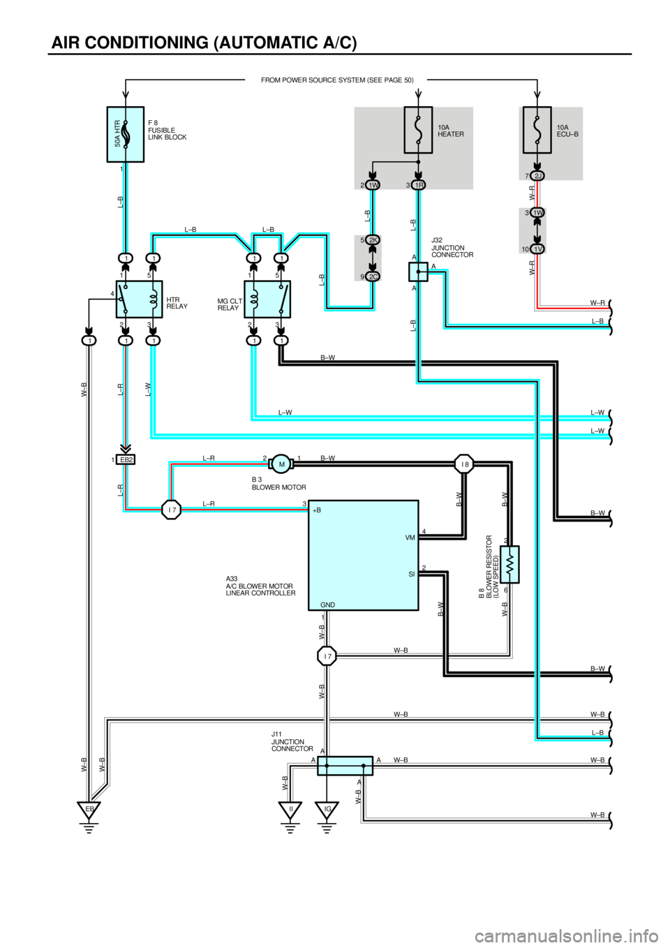
AIR CONDITIONING (AUTOMATIC A/C)
23 41510A
HEATER FROM POWER SOURCE SYSTEM (
SEE PAGE 50)
1W 2
6 2
IG FUS IBL E
LINK BLOCK10A
ECU±B
2J 7
L±B
HTR
RELAY
A/C BLOWER MOTOR
LINEAR CONTROLLER A33
50A HTR
1F 8
1R 3
11111
EB23 15
MG CLT
RELAY
11 11
I 8 2K 5
2C 91W 3
1V 10
21
EB2 1
I 73 L±B L±B
L±R L±R B±W
AA A4
2
B±W
L±B W±B
W±B
W±B W±R
L±B
L±B
L±B
W± R W±R
L±B
L±W
L±W
B±W
L±R
L±W W± B
L±R
B±W
B±W B±W
W±B
L±W
1
W±B W±B
W±B
W±B
L±B W± B
W±B
W±B JUNCTION
CONNECTOR J11 BLOWER MOTOR B 3
BLOWER RESISTOR
(
LOW SPEED) B 8
B±WA A
AJUNCTION
CONNECTOR J32
+B
VM
SI
GND
IIA
W± B
I 7W±B M
Page 4519 of 4592

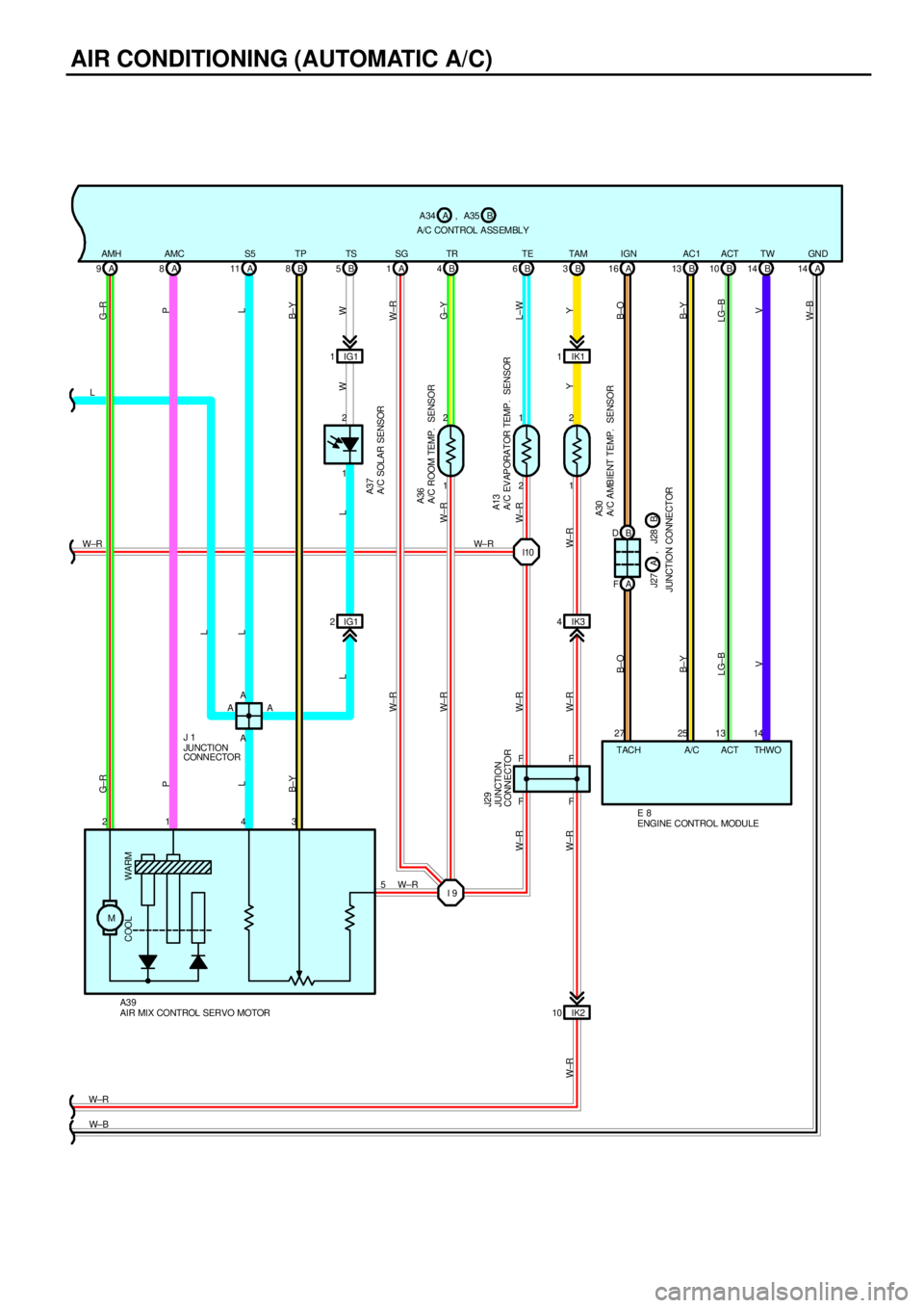
AIR CONDITIONING (AUTOMATIC A/C)
A/C CONTROL A SS EMBLY
1 2
M3 4 1 2
B±YL P G± R
A/C SOLAR SENSOR A37
AIR MIX CONTROL SERVO MOTOR A39
WARM COOL
A/C ROOM TEMP. SENSOR
A/C EVAPORATOR TEMP. SENSORA36
A13
1 2
2 1
1 2
A/C AMBIENT TEMP. SENSOR A30
IK3 4
IK2 10IK1 1A 14 B 14 B 10 B 13 A 16 B 3 B 6 B 4 A 1 B 5 B 8 A 11 A 8 A 9
A FB D IG1 1
IG1 2
W B±YL P G±R
W LL
W±R
G± Y
L±W
Y
B±O
B±Y
LG±B
V
W± B V LG±BB±Y B±OW± R W± R W± R W± R
W±RY
JUNCTION CONNECTOR
W±R
W± BAMH AMC S5 TP TS SG TR TE TAM IGN AC1 ACT TW GND
TACH ACT THWO
W±R L L
5
W±R W±R
27 25 13 14 W±RL
ENGINE CONTROL MODULE E 8A/C B A34 A , A35
B J27 A , J28
F F
F F A A
AA
W±R
W±R JUNCTION
CONNECTOR J29
JUNCTION
CONNECTOR J 1
W± R
I10 W± R
I 9
Page 4521 of 4592

AIR CONDITIONING (AUTOMATIC A/C)
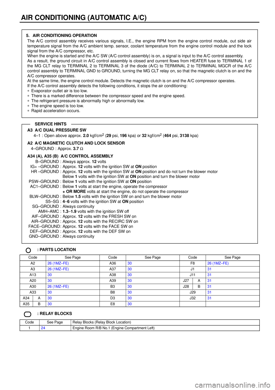
5. AIR CONDITIONING OPERATION
The A/C control assembly receives various signals, I.E., the engine RPM from the engine control module, out side air
temperature signal from the A/C ambient temp. sensor, coolant temperature from the engine control module and the lock
signal from the A/C compressor, etc.
When the engine is started and the A/C SW (A/C control assembly) is on, a signal is input to the A/C control assembly.
As a result, the ground circuit in A/C control assembly is closed and current flows from HEATER fuse to TERMINAL 1 of
the MG CLT relay to TERMINAL 2 to TERMINAL 3 of the diode (A/C) to TERMINAL 2 to TERMINAL MGCR of the A/C
control assembly to TERMINAL GND to GROUND, turning the MG CLT relay on, so that the magnetic clutch is on and the
A/C compressor operates.
At the same time, the engine control module. Detects the magnetic clutch is on and the A/C compressor operates.
If the A/C control assembly detects the following conditions, it stops the air conditioning:
*Evaporator outlet air is too low.
*There is a marked difference between the compressor speed and the engine speed.
*The refrigerant pressure is abnormally high or abnormally low.
*The engine speed is too low.
*Rapid acceleration occurs.
A3 A/C DUAL PRESSURE SW
4±1 : Open above approx. 2.0 kgf/cm2 (29 psi, 196 kpa) or 32 kgf/cm2 (464 psi, 3138 kpa)
A2
A/C MAGNETIC CLUTCH AND LOCK SENSOR
4±GROUND : Approx. 3.7 W
A34 (A), A35 (B) A/C CONTROL ASSEMBLY
B±GROUND : Always approx. 12 volts
IG+ ±GROUND : Approx. 12 volts with the ignition SW at ON position
HR ±GROUND : Approx. 12 volts with the ignition SW at ON position and do not turn the blower motor
Below 1 volts with the ignition SW at ON position and turn the blower motor
PSW±GROUND : Below 1 volts with the ignition SW at ON position
AC1±GROUND : Below 1 volts at start the engine, operate the compressor
+ OR MORE volts at start the engine, do not operate the compressor
BLW±GROUND : Below 1.5 volts with the ignition SW on and turn the blower motor
S5±SG :4±6 volts with the ignition SW at ON position
SG±GROUND : Always continuity
AMH±AMC :1.3±1.9 volts with the ignition SW off
AIF±GROUND : Approx. 12 volts with the FRESH SW on
AIR±GROUND : Approx. 12 volts with the RECIRC SW on
FACE±GROUND: Approx. 12 volts with the FACE SW on
DEF±GROUND : Approx. 12 volts with the DEF SW on
GND±GROUND : Always continuity
: PARTS LOCATION
CodeSee PageCodeSee PageCodeSee Page
A226 (1MZ±FE)A3630F826 (1MZ±FE)
A326 (1MZ±FE)A3730J131
A1330A3830J1131
A2030A3930J27A31
A3026 (1MZ±FE)B330J28B31
A3330B830J2931
A34A30D330J3231
A35B30E830
: RELAY BLOCKS
CodeSee PageRelay Blocks (Relay Block Location)
124Engine Room R/B No.1 (Engine Compartment Left)
SERVICE HINTS