1999 TOYOTA CAMRY window
[x] Cancel search: windowPage 4102 of 4592
ID2 11 ID25ID27ID29ID26ID212
DOWNUP
52
31
21
G
R
P10
POWER WINDOW MOTOR
FRONT RH4
SU SD B
UD
DOWNUP
24
15
21
G
R
P11
POWER WI NDOW MOTOR
REAR LH3
SU SD B
UD
DOWNUP
24
15
21
G
R
P12
POWER WINDOW MOTOR
REAR RH3
SU SD B
UD IL2 4IL25IL26 BA12 BA13 BA11 BB12 BB13 BB11 IC1 1IC15IM15IM17IM19 14 6 9 12 8 13
A AA PU PD RLU RLD RRU RRD
G± W
R±L
G±Y
R±Y
G±B
R±B G±B
R±B R±Y G±YR±L G± W G± W
R±L
G±B
R±BL
L
G±B
R±B
LLR±B
G± BR±Y G± YL R±L G±W
L
LJUNCTION
CONNECTOR J 3
POWER WINDOW CONTROL
SW FRONT RH P 5
POWER WINDOW CONTROL
SW REAR LH P 6
POWER WINDOW CONTROL
SW REAR RH P 7
POWER WINDOW MASTER SW P 8
L
L NORMALLOCKFRONT RH REAR LH REAR RH
WINDOW LOCK SW
M M M
Page 4103 of 4592

POWER WINDOW
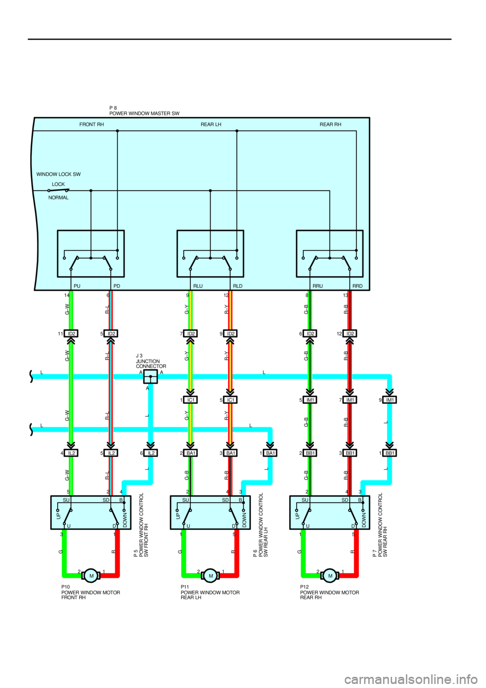
With the ignition SW turned on, current flows through the GAUGE fuse to TERMINAL 7 of the integration relay to TERMINAL
(A) 12 to TERMINAL 1 of the POWER relay to TERMINAL 2 to GROUND, this activates the relay and the current flowing to
TERMINAL 5 of the relay from the POWER fuse flows to TERMINAL 3 of the relay to TERMINALS 10 and 11 of the power
window master SW.
1. MANUAL OPERATION (DRIVER'S WINDOW)
With the ignition SW turned on and with the power window master SW (Driver's) pulled to the up side the current flowing from
TERMINALS 10 and 11 of the power window master SW flows to TERMINAL 1 of the master SW to TERMINAL 1 of the
power window motor to TERMINAL 2 to TERMINAL 5 of the master SW to TERMINALS 3 and 4 to GROUND and causes
the power window motor to rotate in the up direction. The window ascends only while the SW is being pushed.
In down operation, the flow of current from TERMINALS 10 and 11 of the power window master SW to TERMINAL 5 of the
master SW causes the flow of current from TERMINAL 2 of the power window motor to TERMINAL 1 to TERMINAL 1 of the
master SW to TERMINALS 3 and 4 to GROUND, flowing in the opposite detection to manual up operation and causing the
motor to rotate in reverse, lowering the window.
2. AUTO DOWN OPERATION (DRIVER'S WINDOW)
When the driver's window SW is pushed strongly to the down side, the current flowing to TERMINALS 10 and 11 of the
power window master SW flows to the down contact point and auto down contact point of the driver's SW.
This activates the relay (Down side) inside the power window master SW and the hold circuit also turns on at the same time,
so the relay (Down side) remains activated even when the SW is released.
Current flows at this time from TERMINALS 10 and 11 of the power window master SW to TERMINAL 5 to TERMINAL 2 of
the power window motor to TERMINAL 1 to TERMINAL 1 of the power window master SW to TERMINALS 3 and 4 to
GROUND, so the motor continues to operate until the driver's window is fully down.
When the driver's window finishes down operation and the hold circuit goes off, so the relay (Down side) also turns off. This
stops the current flowing from TERMINALS 10 and 11 of the power window master SW to TERMINAL 5 is cut off, so the
power window motor stops and auto down operation stops.
When the driver's SW is pulled to the up side during auto down operation, the hold circuit is turned off so the current flowing
from TERMINALS 10 and 11 of the power window master SW to TERMINAL 5 is cut off and the power window motor stops.
If the SW remains pulled up the relay (Up side) is activated, so current flows from TERMINALS 10 and 11 of the power
window master SW to TERMINAL 1 to TERMINAL 1 of the power window motor to TERMINAL 2 to TERMINAL 5 to
TERMINALS 3 and 4 to GROUND, the power window motor rotates in the up direction and manual up operation occurs
while the SW is pulled up.
3. MANUAL OPERATION (FRONT RH WINDOW)
With the power window control SW front RH pulled to the up side, the current flowing from TERMINAL 4 of the power window
control SW flows to TERMINAL 3 of the power window control SW to TERMINAL 2 of the power window motor to TERMINAL
1 to TERMINAL 1 of the power window control SW to TERMINAL 2 to TERMINAL 6 of the master SW to TERMINALS 3 and
4 to GROUND and causes the power window motor front RH to rotate in the up direction. The up operation continues only
while the power window control SW is pulled to the up side. When the window descends, the current flowing to the motor
flows in the opposite direction, from TERMINAL 1 to TERMINAL 2, and the motor rotates in reverse. When the window lock
SW is pushed to the lock side, the ground circuit to the front RH window becomes open.
As a result, even if Open/Close operation of the front RH window is tried, the current from TERMINALS 3 and 4 of the power
window master SW is not grounded and the motor does not rotate, so the front RH window can not be operated and window
lock occurs.
4. MANUAL OPERATION (REAR LH, RH WINDOW)
With the power window control SW rear LH, RH pulled to the up side, the current flowing from TERMINAL 3 of the power
window control SW flows to TERMINAL 1 of the power control SW to TERMINAL 2 of the power window motor to TERMINAL
1 to TERMINAL 5 of the power window control SW to TERMINAL 4 to TERMINAL 12 or 13 of the master SW to TERMINALS
3 and 4 to GROUND and causes the power window motor rear LH, RH to rotate in the up direction. The up operation
continues only while the power window control SW is pulled to the up side. When the window descends, the current flowing
to the motor flows in the opposite direction, from TERMINAL 1 to TERMINAL 2, and the motor rotates in reverse. When the
window lock SW is pushed to the lock side, the ground circuit to the rear LH, RH window becomes open.
As a result, even if Open/Close operation of the rear LH, RH window is tried, the current from TERMINALS 3 and 4 of the
power window master SW is not grounded and the motor does not rotate, so the rear LH, RH window can not be operated
and window lock occurs.
SYSTEM OUTLINE
Page 4104 of 4592
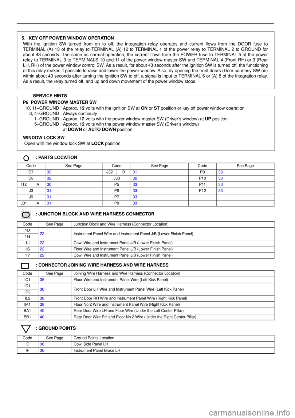
5. KEY OFF POWER WINDOW OPERATION
With the ignition SW turned from on to off, the integration relay operates and current flows from the DOOR fuse to
TERMINAL (A) 13 of the relay to TERMINAL (A) 12 to TERMINAL 1 of the power relay to TERMINAL 2 to GROUND for
about 43 seconds. The same as normal operation, the current flows from the POWER fuse to TERMINAL 5 of the power
relay to TERMINAL 3 to TERMINALS 10 and 11 of the power window master SW and TERMINAL 4 (Front RH) or 3 (Rear
LH, RH) of the power window control SW. As a result, for about 43 seconds after the ignition SW is turned off, the functioning
of this relay makes it possible to raise and lower the power window. Also, by opening the front doors (Door courtesy SW on)
within about 43 seconds after turning the ignition SW to off, a signal is input to TERMINAL 6 or (A) 8 of the integration relay.
As a result, the relay turned off, and up and down movement of the power window stops.
P8 POWER WINDOW MASTER SW
10, 11±GROUND : Approx. 12 volts with the ignition SW at ON or ST position or key off power window operation
3, 4±GROUND : Always continuity
1±GROUND : Approx. 12 volts with the power window master SW (Driver's window) at UP position
5±GROUND : Approx. 12 volts with the power window master SW (Driver's window)
at DOWN or AUTO DOWN position
WINDOW LOCK SW
Open with the window lock SW at LOCK position
: PARTS LOCATION
CodeSee PageCodeSee PageCodeSee Page
D732J32B31P933
D832J3332P1033
I12A30P533P1133
J331P633P1233
J931P733
J31A31P833
������ ���: JUNCTION BLOCK AND WIRE HARNESS CONNECTOR
CodeSee PageJunction Block and Wire Harness (Connector Location)
1D22Instrument Panel Wire and Instrument Panel J/B (Lower Finish Panel)1G22Instrument Panel Wire and Instrument Panel J/B (Lower Finish Panel)
1J22Cowl Wire and Instrument Panel J/B (Lower Finish Panel)
1S22Floor Wire and Instrument Panel J/B (Lower Finish Panel)
1V22Cowl Wire and Instrument Panel J/B (Lower Finish Panel)
: CONNECTOR JOINING WIRE HARNESS AND WIRE HARNESS
CodeSee PageJoining Wire Harness and Wire Harness (Connector Location)
IC136Floor Wire and Instrument Panel Wire (Left Kick Panel)
ID136Front Door LH Wire and Instrument Panel Wire (Left Kick Panel)ID236Front Door LH Wire and Instrument Panel Wire (Left Kick Panel)
IL238Front Door RH Wire and Instrument Panel Wire (Right Kick Panel)
IM138Floor No.2 Wire and Instrument Panel Wire (Right Kick Panel)
BA140Rear Door Wire LH and Floor Wire (Under the Left Center Pillar)
BB140Rear Door Wire RH and Floor No.2 Wire (Under the Right Center Pillar)
: GROUND POINTS
CodeSee PageGround Points Location
ID36Cowl Side Panel LH
IF36Instrument Panel Brace LH
SERVICE HINTS
Page 4105 of 4592
DOOR LOCK CONTROL
A
IFID II 230A
POWER25A
DOOR FROM POWER SOURCE SYSTEM (
SEE PAGE 44)
1D 1
32 51
ID1 13 ID112 ID14ID13IL14IL13IL113 IL112 ID23ID28ID111
ID1 20
IL1 20 1G 12 1J71G5
1G7
1V3
UNLOCK LOCK
4 27
UNLOCK LOCK
1 23
UNLOCK LOCK
1 23
UNLOCK LOCK
3 65
M A 13 A 12A A
A 1A2A3A4A5A 9 B C
A A1 A B B D
EF D
EBBA
AA
AA
AF D
EB
AA W±BL±R
L±B
W±B
W± B W± B LG
L±W
R±G
W±B
W± B
W±B W±B W±B
W± B L± RL±B L±RG LGL L±W R±G L±WG LG W± B
LG
GLG
G
L±W
R±G
L
LG
G L L±W
L±R L±R
L±R W±B W±B
L±WR±B
L±W L
W±B
4 3 2
TO POWER WINDOW
MASTER SWPOWER
RELAY
JUNCTION
CONNECTOR
I12
INTEGRATION RELAY
JUNCTION
CONNECTOR JUNCTION
CONNECTOR J 5
J27 JUNCTION
CONNECTOR J27JUNCTION
CONNECTOR J 5
JUNCTION
CONNECTOR J 5
JUNCTION
CONNE CTORJUNCTION
CONNECTOR
JUNCTION
CONNECTOR J 9J33J35
DOOR LOCK MOTOR AND
DOOR UNLOCK DETECTION
SW FRONT LHDOOR LOCK CONTROL
SW RH DOOR KEY LOCK AND
UNLOCK SW FRONT RH DOOR KEY LOCK AND
UNLOCK SW FRONT LH DOOR LOCK CONTROL SW LH
[POWER WINDOW MASTER SW] P 8
D11
D12
D13
D14
JUNCTION
CONNECTOR J 5
1 2
1M 5 1M 3
W±B L±B
5 10UNLOCK WARNING SW U 110A
GAU GE
7 1
B J31 A , J32
G
L±B
Page 4141 of 4592
REAR WINDOW DEFOGGER AND MIRROR HEATER
1R 31J13
ID II 1V 31G 7A A 10A
HEATER40A
DEF
DEFOGGER
RELAY
JUNCTION
CONNECTOR
FROM POWER SOURCE SYSTEM (
SEE PAGE 44)
W±B W± BB
W±B
13 25
IB1 8 2
IFID1 20 IL120 ID1 5IL15 10A
MIRROR±
HEATER
1T 51D4 1L 1 1J 12
3 A
A
A 45 A
A A
REAR WINDOW
DEFOGGER SW R 4 JUNCTION
CONNECTOR J30
JUNCTION
CONNECTORMIRROR HEATER RH
[REMOTE CONTROL MIRROR RH] MIRROR HEATER LH
[REMOTE CONTROL MIRROR LH]
JUNCTION
CONNECTOR J 9
L±B
L±B Y±G L±B
W±B
W± BW±B
W±B W±B
B±Y B±Y B±Y
B±Y
1
TIMER
CIRCUIT
REAR WINDOW
DEFOGGER
NOISE FILTER
(
REAR WINDOW DEFOGGER) N 211
2
1J 7
W±B
NOISE
FILTER W±B
AW±B
B
E IG D55 11
J35 J33
R14 R13
Page 4142 of 4592
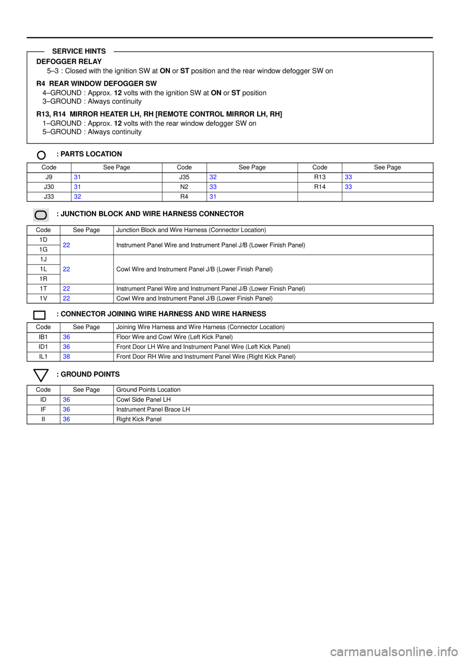
DEFOGGER RELAY
5±3 : Closed with the ignition SW at ON or ST position and the rear window defogger SW on
R4 REAR WINDOW DEFOGGER SW
4±GROUND : Approx. 12 volts with the ignition SW at ON or ST position
3±GROUND : Always continuity
R13, R14 MIRROR HEATER LH, RH [REMOTE CONTROL MIRROR LH, RH]
1±GROUND : Approx. 12 volts with the rear window defogger SW on
5±GROUND : Always continuity
: PARTS LOCATION
CodeSee PageCodeSee PageCodeSee Page
J931J3532R1333
J3031N233R1433
J3332R431
������ ���: JUNCTION BLOCK AND WIRE HARNESS CONNECTOR
CodeSee PageJunction Block and Wire Harness (Connector Location)
1D22Instrument Panel Wire and Instrument Panel J/B (Lower Finish Panel)1G22Instrument Panel Wire and Instrument Panel J/B (Lower Finish Panel)
1J
1L22Cowl Wire and Instrument Panel J/B (Lower Finish Panel)
1R
()
1T22Instrument Panel Wire and Instrument Panel J/B (Lower Finish Panel)
1V22Cowl Wire and Instrument Panel J/B (Lower Finish Panel)
: CONNECTOR JOINING WIRE HARNESS AND WIRE HARNESS
CodeSee PageJoining Wire Harness and Wire Harness (Connector Location)
IB136Floor Wire and Cowl Wire (Left Kick Panel)
ID136Front Door LH Wire and Instrument Panel Wire (Left Kick Panel)
IL138Front Door RH Wire and Instrument Panel Wire (Right Kick Panel)
: GROUND POINTS
CodeSee PageGround Points Location
ID36Cowl Side Panel LH
IF36Instrument Panel Brace LH
II36Right Kick Panel
SERVICE HINTS
Page 4163 of 4592
![TOYOTA CAMRY 1999 Service Repair Manual I GROUND POINT
2K 1J CRUISE CONTROL
ECU
DATA LINK
CONNECTOR 3
POWER RELAY
INTEGRATION RELAY
NOISE FILTER CRUISE CONTROL
ACTUATOR
CRUISE CONTROL SW
[COMB. SW]
LIGHT CONTROL AND
DIMMER SW
[COMB. SW]
TOYOTA CAMRY 1999 Service Repair Manual I GROUND POINT
2K 1J CRUISE CONTROL
ECU
DATA LINK
CONNECTOR 3
POWER RELAY
INTEGRATION RELAY
NOISE FILTER CRUISE CONTROL
ACTUATOR
CRUISE CONTROL SW
[COMB. SW]
LIGHT CONTROL AND
DIMMER SW
[COMB. SW]](/manual-img/14/57448/w960_57448-4162.png)
I GROUND POINT
2K 1J CRUISE CONTROL
ECU
DATA LINK
CONNECTOR 3
POWER RELAY
INTEGRATION RELAY
NOISE FILTER CRUISE CONTROL
ACTUATOR
CRUISE CONTROL SW
[COMB. SW]
LIGHT CONTROL AND
DIMMER SW
[COMB. SW]
KEY INTERLOCK
SOLENOID
UNLOCK WARNING SW
CENTER AIRBAG
SENSOR ASSEMBLY
BRAKE FLUID LEVEL
WARNING SW
BLOWER SW BLOWER RESISTOR
REAR WINDOW
DEFOGGER SW
CI GARETTE LI GHTERWIPER AND WASHER
SW [COMB. SW]
ST RELAY
CENTER AIRBAG
SENSOR
ASSEMBLY
POWER OUTLETA A
A A
A A
A A
A A B A
B A
1J 81M31N1
A A
A
A
A
9
A A
1N3
1V41G 7
1V 3ID1 20
IF ID IHNOISE FILTER W±B
W±B
W±B W±B W±B W±B
W±B W±B
7
W±B
W±B
W± BW±B
W±B
W± B
W± B
JUNCTION
CONNECTOR J 9
W±B W±B
(
CG)
(
E1)
W±B
W±B
W±B
W±B
W± B
J 6
JUNCTION
CONNECTORB A, J 7
DOOR LOCK MOTOR
AND DOOR UNLOCK
DETECTION SW
FRONT L H
DOOR KEY LOCK AND
UNLOCK SW FRONT LH
MIRROR HEATER LH
[REMOTE CONTROL
MIRROR LH]W±B
W±B
W±B
HEATER CONTROL SW
AIR VENT MODE
CONTROL SERVO MOTOR I 3W± B W± B
W±B
ABS ECU AW±B
W±B W±B
A
(
E2)TURN SIGNAL FLASHER
A
W±B
(
GND)
(
GND)
JUNCTION CONNECTOR J33
A W±B
W±BW± B
POWER WINDOW
MASTER SWA
W±B
Page 4169 of 4592

J POWER SOURCE (Current Flow Chart)
Instrument Panel J/B (See Page 22)
FuseSystemPage
5AIGN
Charging
Combination Meter
Electronically Controlled Transmission and A/T Indicator
Engine Control
SRS52
138
102
54
11 7
5ASTARTER
Combination Meter
Electronically Controlled Transmission and A/T Indicator
Engine Control
Starting and Ignition138
102
54
48
7.5AOBDEngine Control54
7.5APANEL
Cigarette Lighter and Clock
Combination Meter
Illumination126
138
80
7.5ARAD±NO.2Radio and Player136
7.5ATURNTurn Signal and Hazard Warning Light72
10AGAUGE
ABS
Back±Up Light
Charging
Combination Meter
Cruise Control
Door Lock Control
Electronically Controlled Transmission and A/T Indicator
Engine Control
Key Reminder and Seat Belt Warning
Light Auto Turn Off
Power Window
Stop Light
Taillight11 2
88
52
138
108
98
102
54
128
68
94
74
84
10AHEATERAir Conditioning
Rear Window Defogger and Mirror Heater148
134
10AMIRROR±HEATEREngine Control
Rear Window Defogger and Mirror Heater54
134
10ATAILEngine Control
Taillight54
84
15ACIG
Cigarette Lighter and Clock
Remote Control Mirror
Shift Lock
SRS126
132
122
11 7
15AECU±IG
ABS
Cruise Control
Radiator Fan and Condenser Fan
Shift Lock11 2
108
144
122
*These are the page numbers of the first page on which the related system is shown.