Page 3128 of 4592
PP0L0±01
± PREPARATIONBODY ELECTRICAL
PP±103
155 Author�: Date�:
EQUIPMENT
Voltmeter
Ammeter
Ohmmeter
Test lead
SyphonBrake fluid level warning switch
Bulb (3.4 W)Fuel sender gauge, Seat belt warning relay
Bulb (21 W)Turn signal flasher relay
Dry cell batteryFuel sender gauge
Torque wrench
Masking tapeRear window defogger wire
Tin foilRear window defogger wire
Page 3130 of 4592
PP0MV±01
± PREPARATIONBODY
PP±105
157 Author�: Date�:
EQUIPMENT
Clip remover
Torque wrench
Drill
Drill bit, diam 3.2 mm (0.126 in.)
Hand riveter
TapeTo avoid surface damage
Adhesive tapeTo avoid surface damage
Adhesive
Cleaner
Shop ragRegulator handle
Water pump pliersWindow regulator
KnifeMoulding
Heat lightMoulding
Piano wireWindshield
Rope (no projections, difficult to break)Seat belt pretensioner disposal
Tire Width: 185 mm (7.28 in.)
Inner diam: 360 mm (14.17 in.)Seatbelt pretensioner disposal
Tire with disc wheel Width: 185 mm (7.28 in.)
Inner diam 360 mm (14.17 in.)Seat belt pretinsioner disposal
Vinyl bagSeat belt pretensioner disposal
Page 3150 of 4592
PP24Z±01
PP±14
± PREPARATIONBODY
56 Author�: Date�:
BODY
EQUIPMENT
Clip remover
Torque wrench
Hog ring pliers
TapeTo avoid surface damage
Adhesive tapeTo avoid surface damage
Adhesive
Cleaner
Shop ragRegulator handle
KnifeMoulding
Piano wireBack window glass
Sealer gun
Brush
Putty spatula
Wooden block or similar objectFor tying both piano wire ends
Page 3172 of 4592

W03508SST
R13455
10 m (33 ft) or more
R06753
RS±20
± SUPPLEMENTAL RESTRAINT SYSTEMSTEERING WHEEL PAD AND SPIRAL CABLE
2165 Author�: Date�:
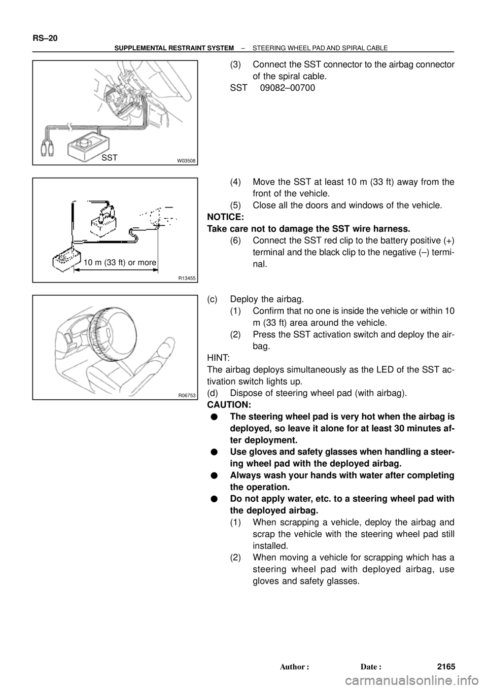
(3) Connect the SST connector to the airbag connector
of the spiral cable.
SST 09082±00700
(4) Move the SST at least 10 m (33 ft) away from the
front of the vehicle.
(5) Close all the doors and windows of the vehicle.
NOTICE:
Take care not to damage the SST wire harness.
(6) Connect the SST red clip to the battery positive (+)
terminal and the black clip to the negative (±) termi-
nal.
(c) Deploy the airbag.
(1) Confirm that no one is inside the vehicle or within 10
m (33 ft) area around the vehicle.
(2) Press the SST activation switch and deploy the air-
bag.
HINT:
The airbag deploys simultaneously as the LED of the SST ac-
tivation switch lights up.
(d) Dispose of steering wheel pad (with airbag).
CAUTION:
�The steering wheel pad is very hot when the airbag is
deployed, so leave it alone for at least 30 minutes af-
ter deployment.
�Use gloves and safety glasses when handling a steer-
ing wheel pad with the deployed airbag.
�Always wash your hands with water after completing
the operation.
�Do not apply water, etc. to a steering wheel pad with
the deployed airbag.
(1) When scrapping a vehicle, deploy the airbag and
scrap the vehicle with the steering wheel pad still
installed.
(2) When moving a vehicle for scrapping which has a
steering wheel pad with deployed airbag, use
gloves and safety glasses.
Page 3184 of 4592

AB0158
SSTBattery
H03287
H08317SST
R13455
10 m (33 ft) or more
H03286
RS±32
± SUPPLEMENTAL RESTRAINT SYSTEMFRONT PASSENGER AIRBAG ASSEMBLY
2177 Author�: Date�:
1. AIRBAG DEPLOYMENT WHEN SCRAPPING VE-
HICLE
HINT:
Have a battery ready as the power source to deploy the airbag.
(a) Check functioning of the SST. (See page RS±18)
SST 09082±00700
(b) Disconnect the airbag connector.
(1) Remove the lower instrument cover inside the No.2
under cover.
NOTICE:
When handling the airbag connector, take care not to dam-
age the airbag wire harness.
(2) Pull up the connector.
(3) Disconnect the airbag connector.
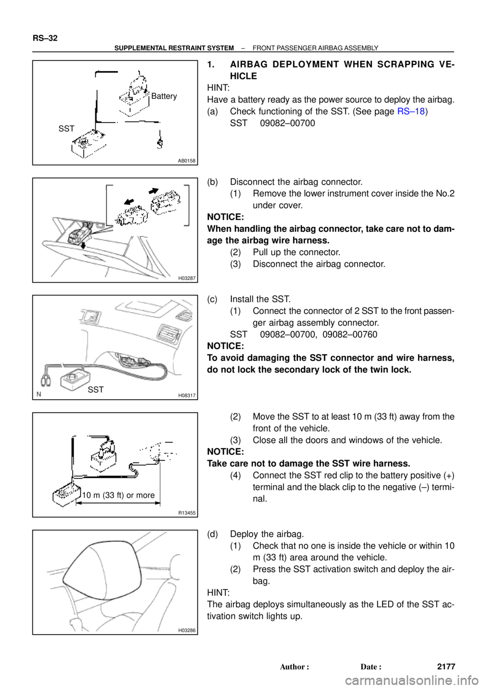
(c) Install the SST.
(1) Connect the connector of 2 SST to the front passen-
ger airbag assembly connector.
SST 09082±00700, 09082±00760
NOTICE:
To avoid damaging the SST connector and wire harness,
do not lock the secondary lock of the twin lock.
(2) Move the SST to at least 10 m (33 ft) away from the
front of the vehicle.
(3) Close all the doors and windows of the vehicle.
NOTICE:
Take care not to damage the SST wire harness.
(4) Connect the SST red clip to the battery positive (+)
terminal and the black clip to the negative (±) termi-
nal.
(d) Deploy the airbag.
(1) Check that no one is inside the vehicle or within 10
m (33 ft) area around the vehicle.
(2) Press the SST activation switch and deploy the air-
bag.
HINT:
The airbag deploys simultaneously as the LED of the SST ac-
tivation switch lights up.
Page 3195 of 4592

AB0158
Battery
SST
H01353
H01354
Battery
SST
R13455
10 m (33 ft) or more
H01326
± SUPPLEMENTAL RESTRAINT SYSTEMSIDE AIRBAG ASSEMBLY (TMC Made)
RS±43
2188 Author�: Date�:
1. AIRBAG DEPLOYMENT WHEN SCRAPPING VE-
HICLE
HINT:
Have a battery ready as the power source to deploy the airbag.
(a) Check functioning of the SST. (See page RS±18)
SST 09082±00700
(b) Disconnect the side airbag connector.
NOTICE:
When handling the airbag connector, take care not to dam-
age the airbag wire harness.
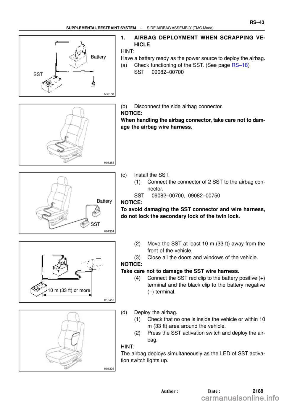
(c) Install the SST.
(1) Connect the connector of 2 SST to the airbag con-
nector.
SST 09082±00700, 09082±00750
NOTICE:
To avoid damaging the SST connector and wire harness,
do not lock the secondary lock of the twin lock.
(2) Move the SST at least 10 m (33 ft) away from the
front of the vehicle.
(3) Close all the doors and windows of the vehicle.
NOTICE:
Take care not to damage the SST wire harness.
(4) Connect the SST red clip to the battery positive (+)
terminal and the black clip to the battery negative
(±) terminal.
(d) Deploy the airbag.
(1) Check that no one is inside the vehicle or within 10
m (33 ft) area around the vehicle.
(2) Press the SST activation switch and deploy the air-
bag.
HINT:
The airbag deploys simultaneously as the LED of SST activa-
tion switch lights up.
Page 3307 of 4592

SS0BY±01
± SERVICE SPECIFICATIONSBODY
SS±69
232 Author�: Date�:
BODY
TORQUE SPECIFICATION
Part tightenedN´mkgf´cmft´lbf
FRONT BUMPER±±±
Front bumper cover x Body5.55549 in.´lbf
Front bumper reinforcement x Body3435025
REAR BUMPER±±±
Rear bumper cover x Body5.05043 in.´lbf
Rear bumper reinforcement x Body3435025
HOOD±±±
Hood hinge x Hood2626019
Hood lock x Body8.08071 in.´lbf
FRONT AND REAR DOOR±±±
Front door hinge x Body3131022
Rear door hinge x Body2626019
Door hinge x Door panel2626019
Door lock striker x Body2626019
Outside rear view mirror x Front door panel5.55549
Door inside handle x Door panel3.53531 in.´lbf
Door glass x Window regulator8.08071 in.´lbf
Window regulator x Door panel5.55549 in.´lbf
Door lock x Door panel5.05043 in.´lbf
Door outside handle x Door panel7.07061 in.´lbf
Door check x Body3030022
Door check x Door panel8.08071 in.´lbf
LUGGAGE COMPARTMENT DOOR AND HINGE±±±
Luggage door hinge x Luggage door8.08071 in.´lbf
Luggage door lock striker x Body5.55549 in.´lbf
Luggage door lock x Luggage door5.55549 in.´lbf
FRONT WIPER AND WASHER±±±
Wiper motor assembly x Body2424518
Wiper arm x Wiper pivot5.55549 in.´lbf
SLIDING ROOF±±±
Sliding roof assembly x Body5.55549 in.´lbf
INSTRUMENT PANEL±±±
Front passenger airbag assembly x Reinforcement2020014
Steering wheel lock nut3536026
SEAT±±±
Front Seat (Power Seat for TMC Made)±±±
Hinge cover x Seatback frame1818513
Seatback frame x Power seat adjuster1515011
Seatback frame x Side airbag assembly6.06153 in.´lbf
Front Seat (Manual Seat for TMC Made)±±±
Front seat adjuster x Body3737527
Page 3673 of 4592

RS3000 TVIP PROGRAMMING CHANGES FOR GBS ± AX006±99 April 23, 1999
Page 2 of 2
When performing the RS3000 System Test, check the Glass Breakage Sensor sensitivity
as follows:
1. Press and release the Remote Control's top button to arm the system.
2. Wait two seconds.
3. With the tip of the ignition key (or striker tool), softly tap the center of the driver's door
window glass.
�If the system is triggered (horn sounds for 20 seconds), the sensitivity must be
adjusted. Turn the Glass Breakage Sensor ECU's adjustment screw clockwise
one notch, and repeat this step again.
4. If the system is not triggered, repeat the glass tapping with moderate force.
�The system should trigger when the glass is tapped with moderate force. If it is
not triggered, turn the Glass Breakage Sensor ECU's adjustment screw clockwise
one notch, and repeat this step again.
CAUTION:
Use caution when performing the step above. Do not tap the window glass with too
much force, or the glass may crack or break. Use extra caution when the temperature
is extremely cold.
NOTE:
The Owner's Guide included in the RS3000 Base Kit is changed to reflect the
(GBS logic) improvement. There is no change to the GBS ECU itself. Repair
Procedure