Page 635 of 4592
N08958
270°
32
1
Z09972
(a)(b)
AB
CAB
C BE±54
± BODY ELECTRICALCOMBINATION METER
2274 Author�: Date�:
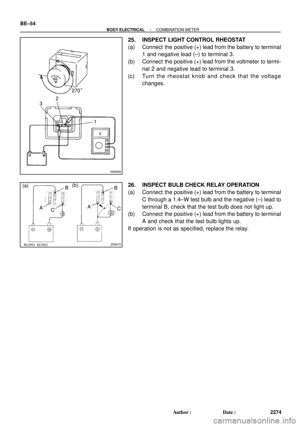
25. INSPECT LIGHT CONTROL RHEOSTAT
(a) Connect the positive (+) lead from the battery to terminal
1 and negative lead (±) to terminal 3.
(b) Connect the positive (+) lead from the voltmeter to termi-
nal 2 and negative lead to terminal 3.
(c) Turn the rheostat knob and check that the voltage
changes.
26. INSPECT BULB CHECK RELAY OPERATION
(a) Connect the positive (+) lead from the battery to terminal
C through a 1.4±W test bulb and the negative (±) lead to
terminal B, check that the test bulb does not light up.
(b) Connect the positive (+) lead from the battery to terminal
A and check that the test bulb lights up.
If operation is not as specified, replace the relay.
Page 637 of 4592

BE0AM±03
N20315
Switch side:
1 2
3
4 5 6
N20314
ON3 4 5
Z08467
1
2
3456 Wire harness side:
S±6±1
N14863
1
2 35 12
35 BE±56
± BODY ELECTRICALDEFOGGER SYSTEM
2276 Author�: Date�:
INSPECTION
1. INSPECT DEFOGGER SWITCH CONTINUITY
Check that is continuity exists between terminals 2 and 6.
If continuity is not as specified, check the bulb.
2. INSPECT DEFOGGER TIMER OPERATION
(a) Connect the positive (+) lead from the battery to terminal
4 and the negative (±) lead to terminal 3.
(b) Connect the positive (+) lead from the battery to terminal
5 through a 3.4±W tester bulb.
(c) Push the defogger switch ON, check that the indicator
light and test bulb light up for 12 to 18 minutes, then the
indicator light and test bulb light goes out.
If operation is not as specified, replace the switch.
3. INSPECT DEFOGGER TIMER CIRCUIT
Disconnect the connector from the switch and inspect the con-
nector on the wire harness side, as shown in the table.
Tester connectionConditionSpecified condition
3 ± GroundConstantContinuity
4 ± GroundIgnition switch LOCK or ACCNo voltage
4 ± GroundIgnition switch ONBattery positive voltage
5 ± GroundIgnition switch LOCK or ACCNo voltage
5 ± GroundIgnition switch ONBattery positive voltage
±Connect terminals 3 and 5.Defogger system operation is normal
If the circuit is not as specified, replace the switch.
4. INSPECT DEFOGGER RELAY CONTINUITY
ConditionTester connectionSpecified condition
Constant1 ± 2Continuity
Apply B+ between
terminals 1 and 2.3 ± 5Continuity
If continuity is not as specified, replace the relay.
Page 642 of 4592

N02358 Unlock
4
8
N02359
4
8
Lock
± BODY ELECTRICALPOWER WINDOW CONTROL SYSTEM
BE±61
2281 Author�: Date�:
Window lock:
Switch positionTester connectionSpecified condition
UP8 ± 9 ± 10Continuity
OFF10 ± 12Continuity
DOWN8 ± 9 ± 12Continuity
(d) Inspect the rear right switch.
Window unlock:
Switch positionTester connectionSpecified condition
UP7 ± 8 ± 9
4 ± 5 ± 14Continuity
OFF4 ± 5 ± 7
4 ± 5 ± 14Continuity
DOWN8 ± 9 ± 14
4 ± 5 ± 7Continuity
Window lock:
Switch positionTester connectionSpecified condition
UP7 ± 8 ± 9Continuity
OFF7 ± 14Continuity
DOWN8 ± 9 ± 14Continuity
If continuity is not as specified, replace the master switch.
2. INSPECT POWER WINDOW MASTER SWITCH ILLU-
MINATION
(a) Set the window lock switch to the unlock position.
(b) Connect the positive (+) lead from the battery to terminal
8 and the negative (±) lead to terminal 4, and check that
all the illuminations light up.
(c) Set the window lock switch to the lock position, check that
all the passenger's power window switch illuminations go
out.
If operation is not as specified, replace the master switch.
Page 693 of 4592
I01474
24 Noise NOISE PRODUCED BY VIBRATION OR SHOCK WHILE DRIVING
Is speaker properly installed?
Is speaker properly installed?
With vehicle stationary lightly tap each system.
Is noise produced?
Noise produced by static electricity accumulated in the vehicle body.Installed properly.
Each system faulty. No
Ye s
No
No Ye s
Ye s BE±112
± BODY ELECTRICALAUDIO SYSTEM
2332 Author�: Date�:
Page 700 of 4592
BE0B2±06
START
Insert the key in the key cylinder.
Under registration
Registration completion
Remove the key.
Will you register the
next key?
NoSecurity indicator blinks until the first
key is inserted. The indicator lights up
after the key registration.
Security Indicator ON
Security Indicator
OFF
END Ye s
Security Indicator ON
(After the last key (sub±key)
has been registered, the indi-
cator goes off.)
± BODY ELECTRICALENGINE IMMOBILISER SYSTEM
BE±119
2339 Author�: Date�:
ENGINE IMMOBILISER SYSTEM
REGISTRATION PROCEDURE
1. KEY REGISTRATION IN AUTOMATIC REGISTRATION MODE
(a) Registration of a new transponder key.
HINT:
�This must be done when you have installed a new ECM.
�The new ECM is in the automatic key code registration mode. The already fixed number of key codes
for this ECM can be registered.
On this type of vehicle, up to 4 key codes can be registered.
�In the automatic registration mode, the last key registered becomes sub±key.
Page 701 of 4592

1.2 Sec.
0.8 Sec.
0.25 Sec. 0.5 Sec.0.25 Sec.
1 Sec. Blinks Code 2±1 Code2±2
0.25 Sec.
0.25 Sec.0.5 Sec. 1 Sec. BE±120
± BODY ELECTRICALENGINE IMMOBILISER SYSTEM
2340 Author�: Date�:
HINT:
�When a key is not inserted in the key cylinder in the automatic registration mode, the security indicator
always lights on.
�When the immobiliser system operations normally and the key is pull out, the security indicator blinks.
�When key code registration could not be performed in the automatic registration mode, code 2±1 is
output from the security indicator and when inserting the already registered key, code 2±2 is output.
(b) Automatic registration mode completion
If completing the mode forcibly when more than 1 key code have been registered in the automatic reg-
istration mode, perform the following procedures.
After 1 more key code have been registered with master key, perform step (1) or (2) without pulling
the key out or inserting the already registered key.
(1) Depress and release brake pedal 5 times or more within 15sec.
(2) With the TOYOTA hand±held tester, require automatic registration mode completion.
Page 710 of 4592

BE16T±01
± BODY ELECTRICALTROUBLESHOOTING
BE±1
533 Author�: Date�:
TROUBLESHOOTING
PROBLEM SYMPTOMS TABLE
COMBINATION METER
METER, GAUGES AND ILLUMINATION:
SymptomSuspect AreaSee page
Tachometer, Fuel Gauge and Engine Coolant Temperature Gauge
do not operate.1. GAUGE Fuse (I/P J/B No.1)
2. Meter Circuit Plate
3. Wire Harness±
BE±4
±
Fuel Gauge does not operate or abnormal operation.
1. Fuel Receiver Gauge
2. Fuel Temperature Sensor (For Delivery Pipe)
3. Fuel Temperature Sensor (For Fuel Tank)
4. Fuel Pressure Sensor (For Delivery Pipe)
5. Fuel Pressure Sensor (For Fuel Pipe)
6. ECM
7. Meter Circuit Plate
8. Wire HarnessBE±5
SF±36
SF±40
SF±42
SF±45
±
BE±4
±
Engine Coolant Temperature Gauge does not operate or abnormal
operation
1. Engine Coolant Temperature Receiver Gauge
2. Engine Coolant Temperature Sender Gauge
3. Meter Circuit Plate
4. Wire HarnessBE±5
BE±5
BE±4
±
All illumination lights do not light up.
1. TAIL Fuse (I/P J/B No.1)
2. Light Control Rheostat
3. Wire Harness±
BE±54*
±
Only one illumination light does not light up.1. Bulb
2. Wire Harness±
±
COMBINATION METER
WARNING LIGHTS:
SymptomSuspect AreaSee page
Warning lights do not light up. (Except Discharge, Open Door and
SRS)1. GAUGE Fuse (I/P J/B No.1)
2. Meter Circuit Plate
3. Wire Harness±
BE±4
±
Low Oil Pressure warning light does not light up.
1. Bulb
2. Low Oil Pressure Warning Switch
3. Meter Circuit Plate
4. Wire Harness±
BE±5
BE±4
±
Fuel Level warning light does not light up.
1. Bulb
2. Fuel Temperature Sensor (For Delivery Pipe)
3. Fuel Temperature Sensor (For Fuel Tank)
4. Fuel Pressure Sensor (For Delivery Pipe)
5. Fuel Pressure Sensor (For Fuel Pipe)
6. ECM
7. Meter Circuit Plate
8. Wire Harness±
SF±36
SF±40
SF±42
SF±45
±
BE±4
±
*: See Pub. No. RM654U
Page 711 of 4592
BE0AI±04
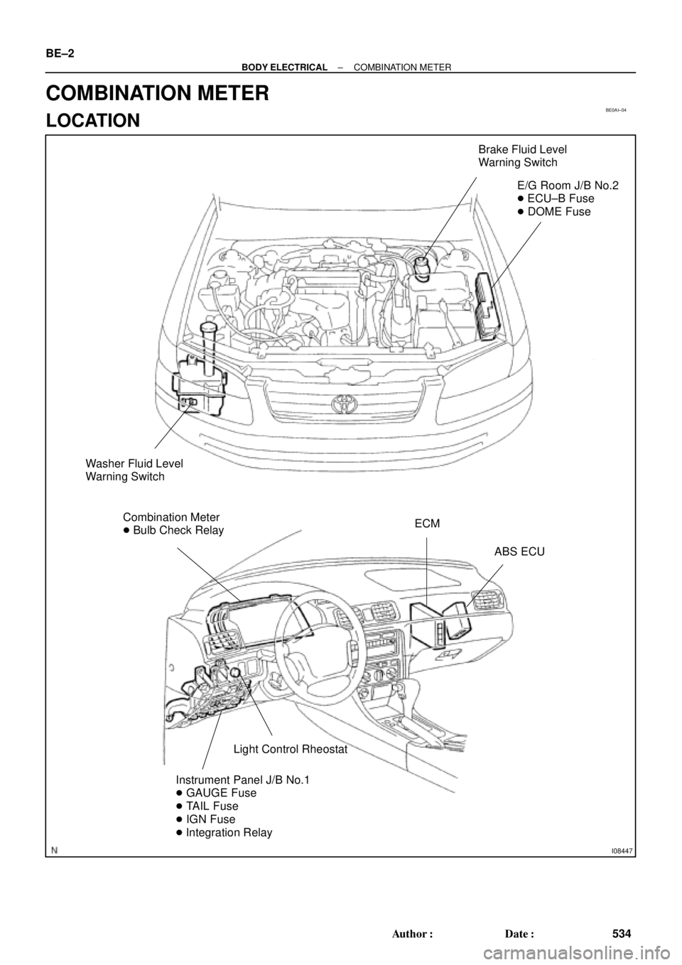
I08447
Brake Fluid Level
Warning Switch
E/G Room J/B No.2
� ECU±B Fuse
� DOME Fuse
Washer Fluid Level
Warning Switch
Combination Meter
� Bulb Check RelayECM
ABS ECU
Light Control Rheostat
Instrument Panel J/B No.1
� GAUGE Fuse
� TAIL Fuse
� IGN Fuse
� Integration Relay
BE±2
± BODY ELECTRICALCOMBINATION METER
534 Author�: Date�:
COMBINATION METER
LOCATION