Page 613 of 4592

BE0AB±03
N21873
w/ Sliding roof:
w/o Sliding roof:21
1
2
N20157
2
Ohmmeter
N20158
2
1Ohmmeter
N20159
ON
OFFOhmmeter BE±32
± BODY ELECTRICALINTERIOR LIGHT SYSTEM
2252 Author�: Date�:
INSPECTION
1. INSPECT MAP LIGHT SWITCH CONTINUITY
Switch positionTester connectionSpecified condition
OFF±No continuity
ON1 ± 2Continuity
If continuity is not as specified, replace the light assembly or
bulb.
2. INSPECT DOME LAMP SWITCH
(a) Disconnect the connector from the dome lamp.
(b) Turn the dome lamp switch ON, check that continuity ex-
ists between terminal 2 and body ground.
(c) Turn the dome lamp switch DOOR, check that there is
continuity exists between terminal 1 and 2.
If operation is not as specified, replace the switch.
3. INSPECT DOOR COURTESY SWITCH CONTINUITY
(a) Check that continuity exists between terminal and the
switch body with the switch ON (switch pin released:
opened door).
(b) Check that no continuity exists between terminal and the
switch body with the switch OFF (switch pin pushed in:
closed doors).
If operation is not as specified, replace the switch.
Page 614 of 4592
I01447
ON
OFF
± BODY ELECTRICALINTERIOR LIGHT SYSTEM
BE±33
2253 Author�: Date�:
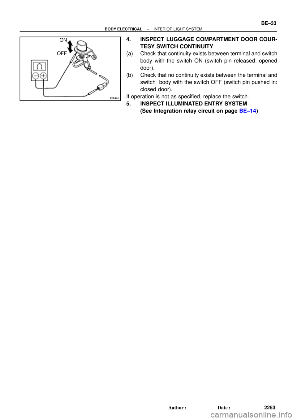
4. INSPECT LUGGAGE COMPARTMENT DOOR COUR-
TESY SWITCH CONTINUITY
(a) Check that continuity exists between terminal and switch
body with the switch ON (switch pin released: opened
door).
(b) Check that no continuity exists between the terminal and
switch body with the switch OFF (switch pin pushed in:
closed door).
If operation is not as specified, replace the switch.
5. INSPECT ILLUMINATED ENTRY SYSTEM
(See Integration relay circuit on page BE±14)
Page 615 of 4592
BE0AC±02
Z19047
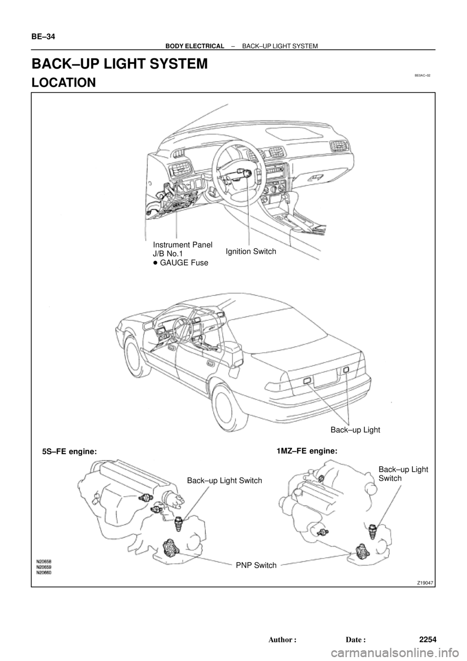
Instrument Panel
J/B No.1
� GAUGE FuseIgnition Switch
Back±up Light
Back±up Light SwitchBack±up Light
Switch
PNP Switch 5S±FE engine:1MZ±FE engine: BE±34
± BODY ELECTRICALBACK±UP LIGHT SYSTEM
2254 Author�: Date�:
BACK±UP LIGHT SYSTEM
LOCATION
Page 616 of 4592
BE0AD±02
N14065
Push
Free
± BODY ELECTRICALBACK±UP LIGHT SYSTEM
BE±35
2255 Author�: Date�:
INSPECTION
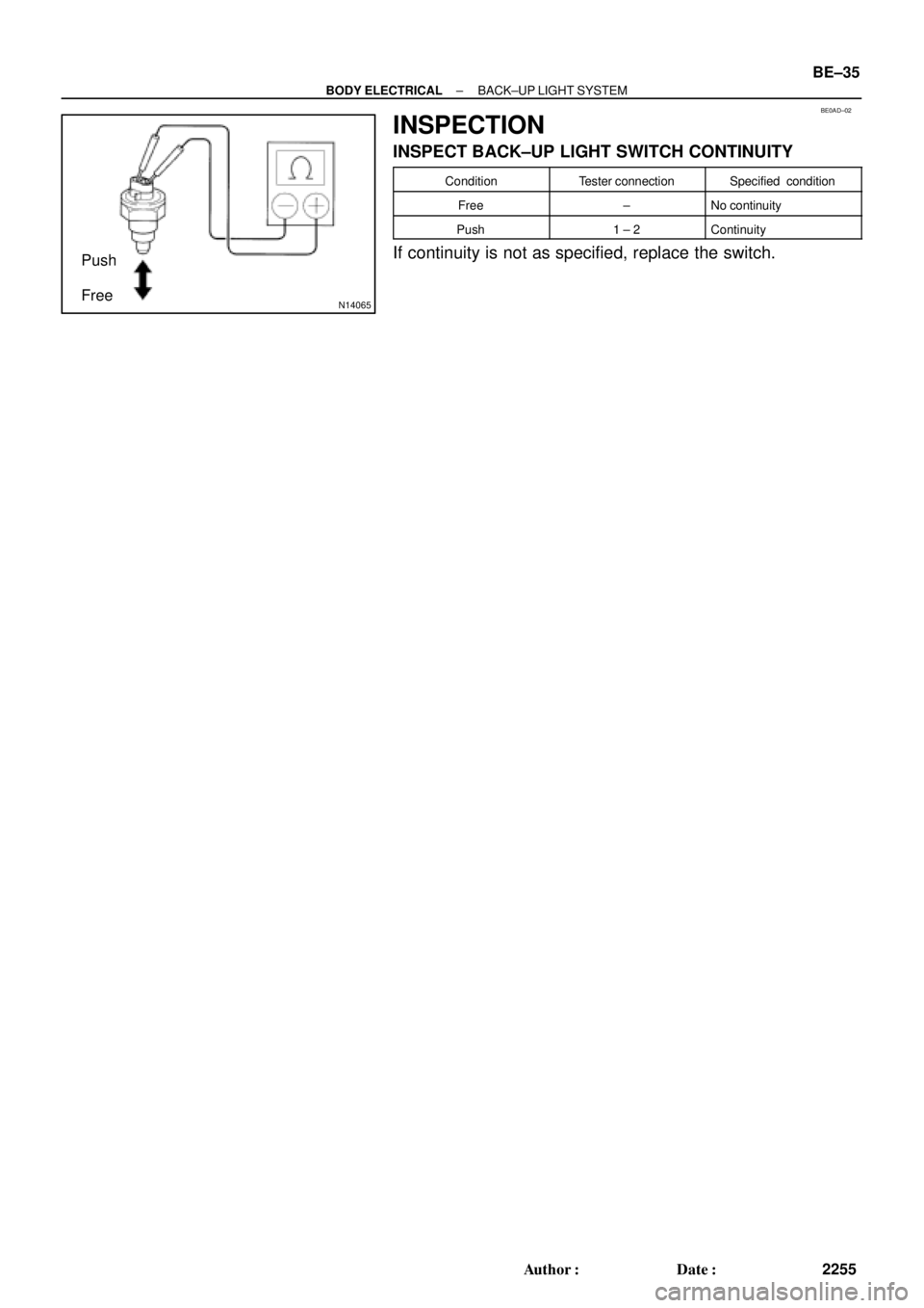
INSPECT BACK±UP LIGHT SWITCH CONTINUITY
ConditionTester connectionSpecified condition
Free±No continuity
Push1 ± 2Continuity
If continuity is not as specified, replace the switch.
Page 617 of 4592
BE0AE±02
Z19048
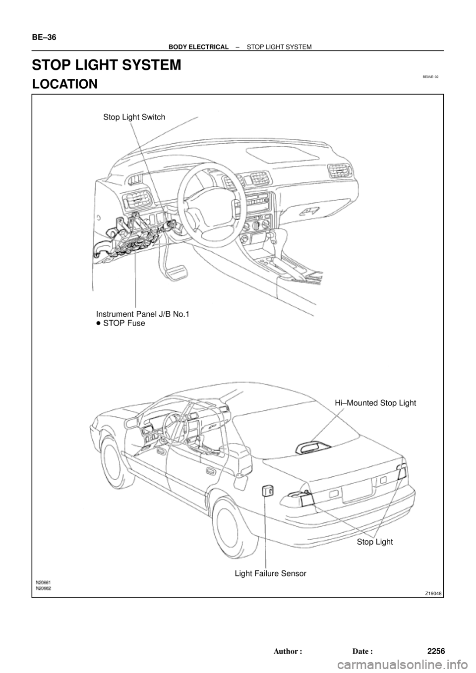
Stop Light Switch
Instrument Panel J/B No.1
� STOP Fuse
Hi±Mounted Stop Light
Stop Light
Light Failure Sensor BE±36
± BODY ELECTRICALSTOP LIGHT SYSTEM
2256 Author�: Date�:
STOP LIGHT SYSTEM
LOCATION
Page 618 of 4592
BE0AF±02
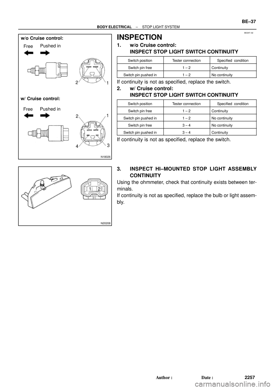
N18026
FreePushed in
FreePushed in w/o Cruise control:
w/ Cruise control:1 2
3 1
2
4
N20208
1
2
± BODY ELECTRICALSTOP LIGHT SYSTEM
BE±37
2257 Author�: Date�:
INSPECTION
1. w/o Cruise control:
INSPECT STOP LIGHT SWITCH CONTINUITY
Switch positionTester connectionSpecified condition
Switch pin free1 ± 2Continuity
Switch pin pushed in1 ± 2No continuity
If continuity is not as specified, replace the switch.
2. w/ Cruise control:
INSPECT STOP LIGHT SWITCH CONTINUITY
Switch positionTester connectionSpecified condition
Switch pin free1 ± 2Continuity
Switch pin pushed in1 ± 2No continuity
Switch pin free3 ± 4No continuity
Switch pin pushed in3 ± 4Continuity
If continuity is not as specified, replace the switch.
3. INSPECT HI±MOUNTED STOP LIGHT ASSEMBLY
CONTINUITY
Using the ohmmeter, check that continuity exists between ter-
minals.
If continuity is not as specified, replace the bulb or light assem-
bly.
Page 619 of 4592

N20209
Wire harness side:
1 2 3 4 5
6 7 8 9 10 11 12
e±12±2±B
BE±38
± BODY ELECTRICALSTOP LIGHT SYSTEM
2258 Author�: Date�:
4. INSPECT LIGHT FAILURE RELAY CIRCUIT
Disconnect the connector from the relay and inspect the con-
nector on the wire harness side, as shown.
Tester connectionConditionSpecified condition
1 ± GroundConstantContinuity*
2 ± GroundConstantContinuity*
9 ± GroundConstantContinuity*
11 ± GroundConstantContinuity
3 ± GroundLight control switch OFFNo voltage
3 ± GroundLight control switch TAIL or HEADBattery positive voltage
4 ± GroundIgnition switch LOCK or ACCNo voltage
4 ± GroundIgnition switch ONBattery positive voltage
7 ± GroundStop light switch OFFNo voltage
7 ± GroundStop light switch ONBattery positive voltage
8 ± GroundIgnition switch LOCK or ACCNo voltage
8 ± GroundIgnition switch ONBattery positive voltage
*: There is resistance because this circuit is grounded through
the bulb.
If the circuit is as specified, replace the relay.
If the circuit is not as specified, inspect the circuits connected
to other parts.
Page 625 of 4592
BE0AI±03
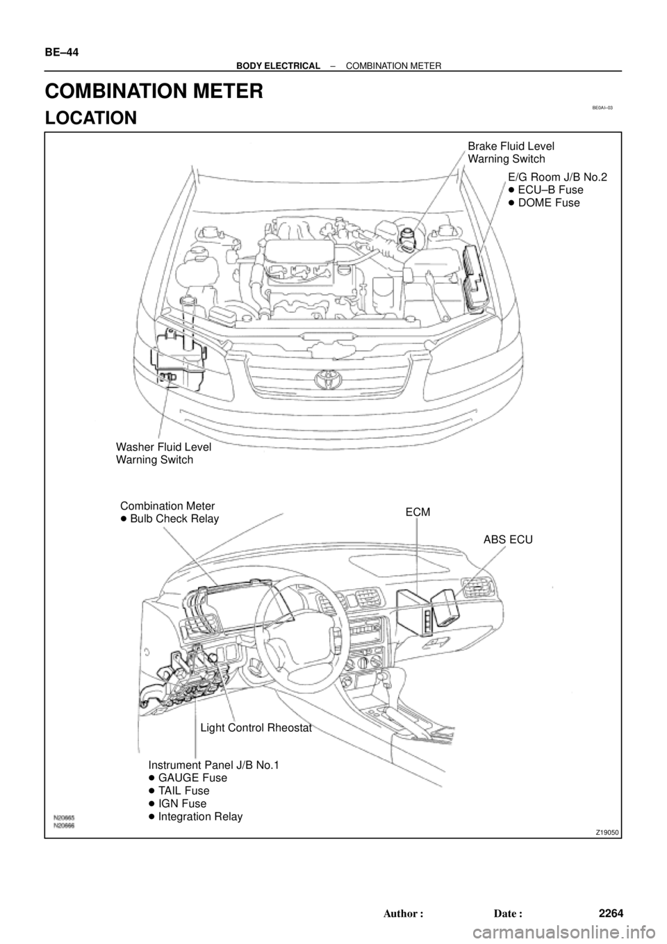
Z19050
Brake Fluid Level
Warning Switch
E/G Room J/B No.2
� ECU±B Fuse
� DOME Fuse
Washer Fluid Level
Warning Switch
Combination Meter
� Bulb Check RelayECM
ABS ECU
Light Control Rheostat
Instrument Panel J/B No.1
� GAUGE Fuse
� TAIL Fuse
� IGN Fuse
� Integration Relay BE±44
± BODY ELECTRICALCOMBINATION METER
2264 Author�: Date�:
COMBINATION METER
LOCATION