Page 171 of 1456

(5) Put new valve guide, coated with sufficient
oil, in cylinder, and insert ST1 into valve guide.
Press in until the valve guide upper end is flush
with the upper surface of ST2.
ST1 499767200 VALVE GUIDE REMOVER
ST2 498267700 VALVE GUIDE ADJUSTER
B2M1398A
(6) Check the valve guide protrusion.
Valve guide protrusion: L
12.0 Ð 12.4 mm (0.472 Ð 0.488 in)
(7) Ream the inside of valve guide with ST.
Gently rotate the reamer clockwise while press-
ing it lightly into valve guide, and return it also
rotating clockwise. After reaming, clean valve
guide to remove chips.
ST 499767400 VALVE GUIDE REAMER
CAUTION:
IApply engine oil to the reamer when ream-
ing.
IIf the inner surface of the valve guide is torn,
the edge of the reamer should be slightly
ground with an oil stone.
IIf the inner surface of the valve guide
becomes lustrous and the reamer does not
chips, use a new reamer or remedy the reamer.
(8) Recheck the contact condition between
valve and valve seat after replacing valve guide.
4. INTAKE AND EXHAUST VALVE
1) Inspect the flange and stem of valve, and
replace if damaged, worn, or deformed, or if ªHº is
less than the specified limit.
H:
Intake
Standard
1.2 mm (0.047 in)
Limit
0.8 mm (0.031 in)
Exhaust
Standard
1.5 mm (0.059 in)
Limit
0.8 mm (0.031 in))
Valve overall length:
Intake
105.9 mm (4.169 in)
Exhaust
106.2 mm (4.181 in)
G2M0153
2) Put a small amount of grinding compound on
the seat surface and lap the valve and seat sur-
face. Install a new intake valve oil seal after lap-
ping.
40
2-3b[W4C4]SERVICE PROCEDURE
4. Cylinder Head
Page 172 of 1456

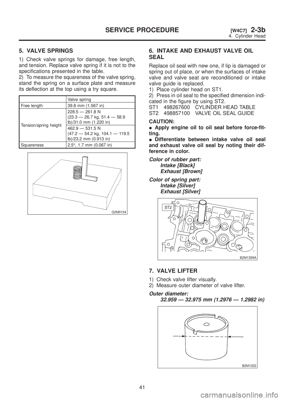
5. VALVE SPRINGS
1) Check valve springs for damage, free length,
and tension. Replace valve spring if it is not to the
specifications presented in the table.
2) To measure the squareness of the valve spring,
stand the spring on a surface plate and measure
its deflection at the top using a try square.
Valve spring
Free length 39.8 mm (1.567 in)
Tension/spring height228.5 Ð 261.8 N
(23.3 Ð 26.7 kg, 51.4 Ð 58.9
lb)/31.0 mm (1.220 in)
462.9 Ð 531.5 N
(47.2 Ð 54.2 kg, 104.1 Ð 119.5
lb)/23.2 mm (0.913 in)
Squareness 2.5É, 1.7 mm (0.067 in)
G2M0154
6. INTAKE AND EXHAUST VALVE OIL
SEAL
Replace oil seal with new one, if lip is damaged or
spring out of place, or when the surfaces of intake
valve and valve seat are reconditioned or intake
valve guide is replaced.
1) Place cylinder head on ST1.
2) Press in oil seal to the specified dimension indi-
cated in the figure by using ST2.
ST1 498267600 CYLINDER HEAD TABLE
ST2 498857100 VALVE OIL SEAL GUIDE
CAUTION:
IApply engine oil to oil seal before force-fit-
ting.
IDifferentiate between intake valve oil seal
and exhaust valve oil seal by noting their dif-
ference in color.
Color of rubber part:
Intake [Black]
Exhaust [Brown]
Color of spring part:
Intake [Silver]
Exhaust [Silver]
B2M1399A
7. VALVE LIFTER
1) Check valve lifter visually.
2) Measure outer diameter of valve lifter.
Outer diameter:
32.959 Ð 32.975 mm (1.2976 Ð 1.2982 in)
B2M1222
41
[W4C7]2-3bSERVICE PROCEDURE
4. Cylinder Head
Page 174 of 1456
1) Installation of valve spring and valve
(1) Coat stem of each valve with engine oil and
insert valve into valve guide.
CAUTION:
When inserting valve into valve guide, use spe-
cial care not to damage the oil seal lip.
(2) Set cylinder head on ST1.
(3) Install valve spring and retainer using ST2.
ST1 498267600 CYLINDER HEAD TABLE
ST2 499718000 VALVE SPRING REMOVER
CAUTION:
Be sure to install the valve springs with their
close-coiled end facing the seat on the cylinder
head.
B2M1221A
(4) Compress valve spring and fit valve spring
retainer key.
(5) After installing, tap valve spring retainers
lightly with wooden hammer for better seating.
2) Install valve lifter and valve shim.
43
[W4D0]2-3bSERVICE PROCEDURE
4. Cylinder Head
Page 175 of 1456
E: INSTALLATION
1. CYLINDER HEAD
S2M0421B
(1) Bolt
(2) Cylinder head bolt(3) Cylinder head
(4) Cylinder head gasket
1) Install cylinder head and gaskets on cylinder
block.
CAUTION:
Use new cylinder head gaskets.
2) Tighten cylinder head bolts.
(1) Apply a coat of engine oil to washers and
bolt threads.
(2) Tighten all bolts to 29 N´m (3.0 kg-m, 22
ft-lb) in alphabetical sequence.
Then tighten all bolts to 69 N´m (7.0 kg-m, 51
ft-lb) in alphabetical sequence.
(3) Back off all bolts by 180É first; back them off
by 180É again.(4) Tighten bolts (A) and (B) to 34 N´m (3.5
kg-m, 25 ft-lb).
B2M1397D
44
2-3b[W4E1]SERVICE PROCEDURE
4. Cylinder Head
Page 195 of 1456
2. CYLINDER BLOCK
B2M2407A
(1) Crankshaft bearing
(2) Crankshaft
(3) Cylinder block(4) Rear oil sealTightening torque: N´m (kg-m, ft-lb)
T1:
25±2 (2.5±0.2, 18.1±1.4)
T2:47±3 (4.8±0.3, 34.7±2.2)
1) Install ST to cylinder block, then install crank-
shaft bearings.
ST 499817000 ENGINE STAND
CAUTION:
Remove oil the mating surface of bearing and
cylinder block before installation. Also apply a
coat of engine oil to crankshaft pins.
2) Position crankshaft on the #2 and #4 cylinder
block.3) Apply fluid packing to the mating surface of #1
and #3 cylinder block, and position it on #2 and #4
cylinder block.
Fluid packing:
THREE BOND 1215 or equivalent
CAUTION:
Do not allow fluid packing to jut into O-ring
grooves, oil passages, bearing grooves, etc.
G2M0185
64
2-3b[W5D2]SERVICE PROCEDURE
5. Cylinder Block
Page 197 of 1456
3. PISTON AND PISTON PIN (#1 AND #2)
B2M1322E
(1) Piston
(2) Piston pin
(3) Circlip(4) Gasket
(5) Service hole plugTightening torque: N´m (kg-m, ft-lb)
T:
69±7 (7.0±0.7, 50.6±5.1)
1) Installing piston
(1) Turn cylinder block so that #1 and #2 cylin-
ders face upward.
(2) Using ST1, turn crankshaft so that #1 and
#2 connecting rods are set at bottom dead cen-
ter.
ST1 499987500 CRANKSHAFT SOCKET
(3) Apply a coat of engine oil to pistons and
cylinders and insert pistons in their cylinders by
using ST2.
ST2 498747300 PISTON GUIDE
S2M0306A
2) Installing piston pin
(1) Insert ST3 into service hole to align piston
pin hole with connecting rod small end.
CAUTION:
Apply a coat of engine oil to ST3 before inser-
tion.
ST3 499017100 PISTON PIN GUIDE
G2M0189
(2) Apply a coat of engine oil to piston pin and
insert piston pin into piston and connecting rod
through service hole.
66
2-3b[W5D3]SERVICE PROCEDURE
5. Cylinder Block
Page 202 of 1456

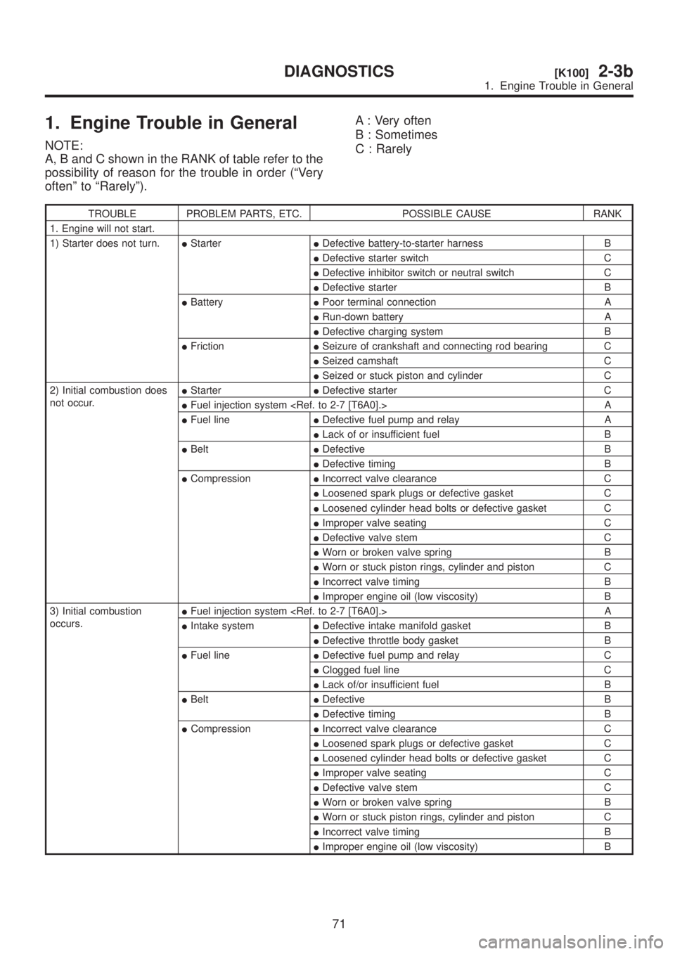
1. Engine Trouble in General
NOTE:
A, B and C shown in the RANK of table refer to the
possibility of reason for the trouble in order (ªVery
oftenº to ªRarelyº).A : Very often
B : Sometimes
C : Rarely
TROUBLE PROBLEM PARTS, ETC. POSSIBLE CAUSE RANK
1. Engine will not start.
1) Starter does not turn.IStarterIDefective battery-to-starter harness B
IDefective starter switch C
IDefective inhibitor switch or neutral switch C
IDefective starter B
IBatteryIPoor terminal connection A
IRun-down battery A
IDefective charging system B
IFrictionISeizure of crankshaft and connecting rod bearing C
ISeized camshaft C
ISeized or stuck piston and cylinder C
2) Initial combustion does
not occur.IStarterIDefective starter C
IFuel injection system A
IFuel lineIDefective fuel pump and relay A
ILack of or insufficient fuel B
IBeltIDefective B
IDefective timing B
ICompressionIIncorrect valve clearance C
ILoosened spark plugs or defective gasket C
ILoosened cylinder head bolts or defective gasket C
IImproper valve seating C
IDefective valve stem C
IWorn or broken valve spring B
IWorn or stuck piston rings, cylinder and piston C
IIncorrect valve timing B
IImproper engine oil (low viscosity) B
3) Initial combustion
occurs.IFuel injection system A
IIntake systemIDefective intake manifold gasket B
IDefective throttle body gasket B
IFuel lineIDefective fuel pump and relay C
IClogged fuel line C
ILack of/or insufficient fuel B
IBeltIDefective B
IDefective timing B
ICompressionIIncorrect valve clearance C
ILoosened spark plugs or defective gasket C
ILoosened cylinder head bolts or defective gasket C
IImproper valve seating C
IDefective valve stem C
IWorn or broken valve spring B
IWorn or stuck piston rings, cylinder and piston C
IIncorrect valve timing B
IImproper engine oil (low viscosity) B
71
[K100]2-3bDIAGNOSTICS
1. Engine Trouble in General
Page 203 of 1456
![SUBARU LEGACY 1999 Service Repair Manual TROUBLE PROBLEM PARTS, ETC. POSSIBLE CAUSE RANK
4) Engine stalls after initial
combustion.IFuel injection system <Ref. to 2-7 [T6A0].> A
IIntake systemILoosened or cracked intake duct B
ILoosened or c SUBARU LEGACY 1999 Service Repair Manual TROUBLE PROBLEM PARTS, ETC. POSSIBLE CAUSE RANK
4) Engine stalls after initial
combustion.IFuel injection system <Ref. to 2-7 [T6A0].> A
IIntake systemILoosened or cracked intake duct B
ILoosened or c](/manual-img/17/57435/w960_57435-202.png)
TROUBLE PROBLEM PARTS, ETC. POSSIBLE CAUSE RANK
4) Engine stalls after initial
combustion.IFuel injection system A
IIntake systemILoosened or cracked intake duct B
ILoosened or cracked PCV hose C
ILoosened or cracked vacuum hose C
IDefective intake manifold gasket B
IDefective throttle body gasket B
IDirty air cleaner element C
IFuel lineIClogged fuel line C
ILack of or insufficient fuel B
IBeltIDefective B
IDefective timing B
ICompressionIIncorrect valve clearance C
ILoosened spark plugs or defective gasket C
ILoosened cylinder head bolts or defective gasket C
IImproper valve seating C
IDefective valve stem C
IWorn or broken valve spring B
IWorn or stuck piston rings, cylinder and piston C
IIncorrect valve timing B
IImproper engine oil (low viscosity) B
2. Rough idle and engine
stallIFuel injection system A
IIntake systemILoosened or cracked intake duct A
ILoosened or cracked PCV hose A
ILoosened or cracked vacuum hose A
IDefective intake manifold gasket B
IDefective throttle body gasket B
IDefective PCV valve C
ILoosened oil filler cap B
IDirty air cleaner element C
IFuel lineIDefective fuel pump and relay C
IClogged fuel line C
ILack of/or insufficient fuel B
IBeltIDefective timing C
ICompressionIIncorrect valve clearance B
ILoosened spark plugs or defective gasket B
ILoosened cylinder head bolts or defective gasket B
IImproper valve seating B
IDefective valve stem C
IWorn or broken valve spring B
IWorn or stuck piston rings, cylinder and piston B
IIncorrect valve timing A
IImproper engine oil (low viscosity) B
ILubrication systemIIncorrect oil pressure B
IDefective rocker cover gasket C
ICooling systemIOverheating C
IOthersIMalfunction of evaporative emission control system A
IStuck or damaged throttle valve B
IAccelerator cable out of adjustment C
72
2-3b[K100]DIAGNOSTICS
1. Engine Trouble in General