1999 SUBARU LEGACY engine oil
[x] Cancel search: engine oilPage 131 of 1456
![SUBARU LEGACY 1999 Service Repair Manual TROUBLE PROBLEM PARTS, ETC. POSSIBLE CAUSE RANK
10. Excessive fuel consump-
tionIFuel injection system <Ref. to 2-7 [T6A0].> A
IIntake systemIDirty air cleaner element A
IBeltIDefective timing B
IComp SUBARU LEGACY 1999 Service Repair Manual TROUBLE PROBLEM PARTS, ETC. POSSIBLE CAUSE RANK
10. Excessive fuel consump-
tionIFuel injection system <Ref. to 2-7 [T6A0].> A
IIntake systemIDirty air cleaner element A
IBeltIDefective timing B
IComp](/manual-img/17/57435/w960_57435-130.png)
TROUBLE PROBLEM PARTS, ETC. POSSIBLE CAUSE RANK
10. Excessive fuel consump-
tionIFuel injection system
IIntake systemIDirty air cleaner element A
IBeltIDefective timing B
ICompressionIIncorrect valve clearance B
ILoosened spark plugs or defective gasket C
ILoosened cylinder head bolts or defective gasket C
IImproper valve seating B
IDefective valve stem C
IWorn or broken valve spring C
IWorn or stuck piston rings, cylinder and piston B
IIncorrect valve timing B
ILubrication systemIIncorrect oil pressure C
ICooling systemIOver cooling C
IOthersIAccelerator cable out of adjustment B
77
[K100]2-3aDIAGNOSTICS
1. Engine Trouble in General
Page 132 of 1456

2. Engine Noise
Type of sound Condition Possible cause
Regular clicking soundSound increases as engine
speed increases.IValve mechanism is defective.
IIncorrect valve clearance
IWorn valve rocker
IWorn camshaft
IBroken valve spring
Heavy and dull clankOil pressure is low.IWorn crankshaft main bearing
IWorn connecting rod bearing (big end)
Oil pressure is normal.ILoose flywheel mounting bolts
IDamaged engine mounting
High-pitched clank
(Spark knock)Sound is noticeable when
accelerating with an overload.IIgnition timing advanced
IAccumulation of carbon inside combustion chamber
IWrong spark plug
IImproper gasoline
Clank when engine speed is
medium (1,000 to 2,000 rpm)Sound is reduced when fuel
injector connector of noisy cyl-
inder is disconnected.
(NOTE*)IWorn crankshaft main bearing
IWorn bearing at crankshaft end of connecting rod
Knocking sound when engine
is operating under idling speed
and engine is warmSound is reduced when fuel
injector connector of noisy cyl-
inder is disconnected.
(NOTE*)IWorn cylinder liner and piston ring
IBroken or stuck piston ring
IWorn piston pin and hole at piston end of connecting rod
Sound is not reduced if each
fuel injector connector is dis-
connected in turn. (NOTE*)IUnusually worn valve lifter
IWorn cam gear
IWorn camshaft journal bore in crankcase
Squeaky sound ÐIInsufficient generator lubrication
Rubbing sound ÐIDefective generator brush and rotor contact
Gear scream when starting
engineÐIDefective ignition starter switch
IWorn gear and starter pinion
Sound like polishing glass with
a dry clothÐILoose drive belt
IDefective engine coolant pump shaft
Hissing sound ÐILoss of compression
IAir leakage in air intake system, hoses, connections or
manifolds
Timing belt noise ÐILoose timing belt
IBelt contacting case/adjacent part
Valve tappet noise ÐIIncorrect valve clearance
NOTE*:
When disconnecting fuel injector connector, Malfunction Indicator Light (CHECK ENGINE light) illuminates and trouble code is
stored in ECM memory.
Therefore, carry out the CLEAR MEMORY MODE
necting fuel injector connector.
78
2-3a[K200]DIAGNOSTICS
2. Engine Noise
Page 133 of 1456

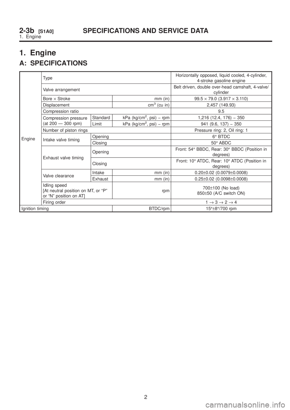
1. Engine
A: SPECIFICATIONS
EngineTypeHorizontally opposed, liquid cooled, 4-cylinder,
4-stroke gasoline engine
Valve arrangementBelt driven, double over-head camshaft, 4-valve/
cylinder
Bore´Stroke mm (in) 99.5´79.0 (3.917´3.110)
Displacement cm
3(cu in) 2,457 (149.93)
Compression ratio 9.5
Compression pressure
(at 200 Ð 300 rpm)Standard kPa (kg/cm
2, psi) þ rpm 1,216 (12.4, 176) þ 350
Limit kPa (kg/cm2, psi) þ rpm 941 (9.6, 137) þ 350
Number of piston rings Pressure ring: 2, Oil ring: 1
Intake valve timingOpening 6É BTDC
Closing 50É ABDC
Exhaust valve timingOpeningFront: 54É BBDC, Rear: 30É BBDC (Position in
degrees)
ClosingFront: 10É ATDC, Rear: 10É ATDC (Position in
degrees)
Valve clearanceIntake mm (in) 0.20±0.02 (0.0079±0.0008)
Exhaust mm (in) 0.25±0.02 (0.0098±0.0008)
Idling speed
[At neutral position on MT, or ªPº
or ªNº position on AT]rpm700±100 (No load)
850±50 (A/C switch ON)
Firing order 1®3®2®4
Ignition timing BTDC/rpm 15ɱ8É/700 rpm
2
2-3b[S1A0]SPECIFICATIONS AND SERVICE DATA
1. Engine
Page 134 of 1456

B: SERVICE DATA
NOTE:
STD: Standard, I.D.: Inner Diameter, O.D.: Outer Diameter, OS: Oversize, US: Undersize
Belt ten-
sion
adjusterProtrusion of adjuster rod 5.2 Ð 6.2 mm (0.205 Ð 0.244 in)
Belt ten-
sionerSpacer O.D. 17.955 Ð 17.975 mm (0.7069 Ð 0.7077 in)
Tensioner bush I.D. 18.00 Ð 18.08 mm (0.7087 Ð 0.7118 in)
Clearance between spacer and
bushSTD 0.025 Ð 0.125 mm (0.0010 Ð 0.0049 in)
Limit 0.175 mm (0.0069 in)
Side clearance of spacerSTD 0.2 Ð 0.55 mm (0.0079 Ð 0.0217 in)
Limit 0.81 mm (0.0319 in)
CamshaftBend limit 0.020 mm (0.0008 in)
Thrust clearanceSTD 0.040 Ð 0.080 mm (0.0016 Ð 0.0031 in)
Limit 0.10 mm (0.0039 in)
Cam lobe heightIntakeSTD 42.20 Ð 42.30 mm (1.6614 Ð 1.6654 in)
Limit 42.04 mm (1.6551 in)
ExhaustSTDFront: 42.50 Ð 42.60 mm
Rear: 41.40 Ð 41.50 mm(1.6732 Ð 1.6772 in) (1.6299
Ð 1.6339 in)
LimitFront: 42.34 mm Rear: 41.24
mm(1.6669 in) (1.6236 in)
Camshaft journal O.D.Front 31.946 Ð 31.963 mm (1.2577 Ð 1.2584 in)
Center 27.946 Ð 27.963 mm (1.1002 Ð 1.1009 in)
Rear 27.946 Ð 27.963 mm (1.1002 Ð 1.1009 in)
Camshaft journal hole I.D.Front 32.000 Ð 32.018 mm (1.2598 Ð 1.2605 in)
Center 28.000 Ð 28.018 mm (1.1024 Ð 1.1031 in)
Rear 28.000 Ð 28.018 mm (1.1024 Ð 1.1031 in)
Oil clearanceSTD 0.037 Ð 0.072 mm (0.0015 Ð 0.0028 in)
Limit 0.10 mm (0.0039 in)
Cylinder
headSurface warpage limit 0.05 mm (0.0020 in)
Surface grinding limit 0.3 mm (0.012 in)
Standard height 127.5 mm (5.02 in)
Valve seatRefacing angle 90É
Contacting widthIntakeSTD 1.0 mm (0.039 in)
Limit 1.7 mm (0.067 in)
ExhaustSTD 1.5 mm (0.059 in)
Limit 2.2 mm (0.087 in)
Valve guideInner diameter 6.000 Ð 6.015 mm (0.2362 Ð 0.2368 in)
Protrusion above head 12.0 Ð 12.4 mm (0.472 Ð 0.488 in)
ValveHead edge thicknessIntakeSTD 1.2 mm (0.047 in)
Limit 0.8 mm (0.031 in)
ExhaustSTD 1.5 mm (0.059 in)
Limit 0.8 mm (0.031 in)
Stem diameterIntake 5.950 Ð 5.965 mm (0.2343 Ð 0.2348 in)
Exhaust 5.950 Ð 5.965 mm (0.2343 Ð 0.2348 in)
Stem oil clearanceSTDIntake 0.035 Ð 0.062 mm (0.0014 Ð 0.0024 in)
Exhaust 0.040 Ð 0.067 mm (0.0016 Ð 0.0026 in)
Limit Ð 0.15 mm (0.0059 in)
Overall lengthIntake 105.9 mm (4.169 in)
Exhaust 106.2 mm (4.181 in)
3
[S1B0]2-3bSPECIFICATIONS AND SERVICE DATA
1. Engine
Page 135 of 1456

Valve
springFree length 48.04 mm (1.8913 in)
Squareness 2.5É, 2.1 mm (0.083 in)
Tension/spring height146.1 Ð 167.7 N (14.9 Ð 17.1 kg, 32.9 Ð 37.7 lb)/42.0 mm
(1.654 in) 455.0 Ð 523.7 N (46.4 Ð 53.4 kg, 102.3 Ð 117.7
lb)/33.4 mm (1.315 in)
Cylinder
blockSurface warpage limit (mating with cylinder head) 0.05 mm (0.0020 in)
Surface grinding limit 0.1 mm (0.004 in)
Cylinder bore STDA 99.505 Ð 99.515 mm (3.9175 Ð 3.9179 in)
B 99.495 Ð 99.505 mm (3.9171 Ð 3.9175 in)
TaperSTD 0.015 mm (0.0006 in)
Limit 0.050 mm (0.0020 in)
Out-of-roundnessSTD 0.010 mm (0.0004 in)
Limit 0.050 mm (0.0020 in)
Piston clearanceSTD 0.010 Ð 0.030 mm (0.0004 Ð 0.0012 in)
Limit 0.050 mm (0.0020 in)
Enlarging (boring) limit 0.5 mm (0.020 in)
Piston Outer diameterSTDA 99.485 Ð 99.495 mm (3.9167 Ð 3.9171 in)
B 99.475 Ð 99.485 mm (3.9163 Ð 3.9167 in)
0.25 mm (0.0098 in) OS 99.725 Ð 99.735 mm (3.9262 Ð 3.9266 in)
0.50 mm (0.0197 in) OS 99.975 Ð 99.985 mm (3.9360 Ð 3.9364 in)
Piston pinStandard clearance between piston
pin and hole in pistonSTD 0.004 Ð 0.010 mm (0.0002 Ð 0.0004 in)
Limit 0.020 mm (0.0008 in)
Degree of fitPiston pin must be fitted into position with thumb at 20ÉC
(68ÉF).
Piston ringPiston ring gapTop ringSTD 0.20 Ð 0.35 mm (0.0079 Ð 0.0138 in)
Limit 1.0 mm (0.039 in)
Second
ringSTD 0.37 Ð 0.52 mm (0.0146 Ð 0.0205 in)
Limit 1.0 mm (0.039 in)
Oil ringSTD 0.20 Ð 0.60 mm (0.0079 Ð 0.0236 in)
Limit 1.5 mm (0.059 in)
Clearance between
piston ring and piston
ring grooveTop ringSTD 0.040 Ð 0.080 mm (0.0016 Ð 0.0031 in)
Limit 0.15 mm (0.0059 in)
Second
ringSTD 0.030 Ð 0.070 mm (0.0012 Ð 0.0028 in)
Limit 0.15 mm (0.0059 in)
Connecting
rodBend twist per 100 mm (3.94 in) in
lengthLimit 0.10 mm (0.0039 in)
Side clearanceSTD 0.070 Ð 0.330 mm (0.0028 Ð 0.0130 in)
Limit 0.4 mm (0.016 in)
Connecting
rod bearingOil clearanceSTD 0.010 Ð 0.038 mm (0.0004 Ð 0.0015 in)
Limit 0.05 mm (0.0020 in)
Thickness at center portionSTD 1.492 Ð 1.501 mm (0.0587 Ð 0.0591 in)
0.03 mm
(0.0012 in)
US1.510 Ð 1.513 mm (0.0594 Ð 0.0596 in)
0.05 mm
(0.0020 in)
US1.520 Ð 1.523 mm (0.0598 Ð 0.0600 in)
0.25 mm
(0.0098 in)
US1.620 Ð 1.623 mm (0.0638 Ð 0.0639 in)
Connecting
rod bush-
ingClearance between piston pin and
bushingSTD 0 Ð 0.022 mm (0 Ð 0.0009 in)
Limit 0.030 mm (0.0012 in)
4
2-3b[S1B0]SPECIFICATIONS AND SERVICE DATA
1. Engine
Page 136 of 1456

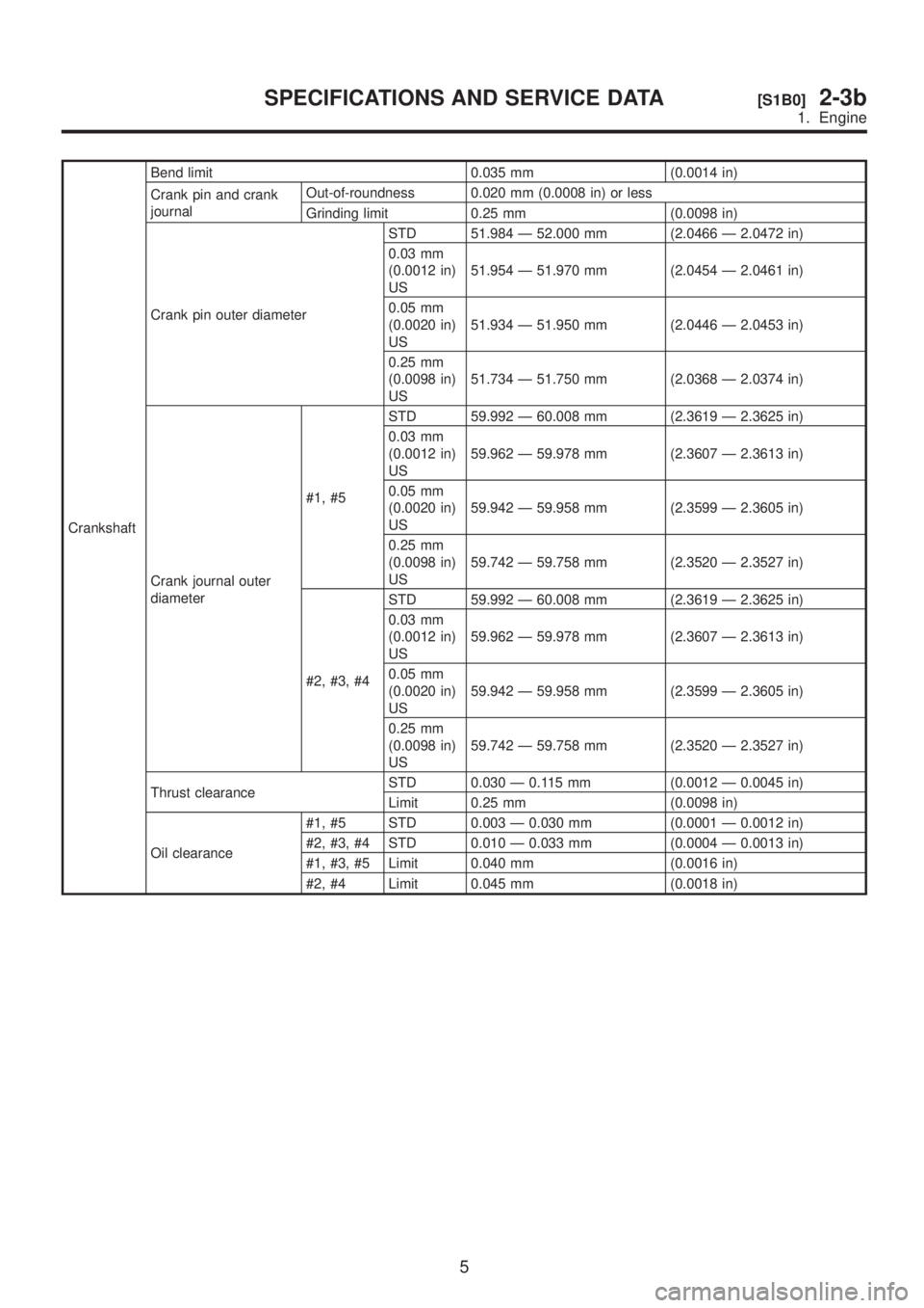
CrankshaftBend limit 0.035 mm (0.0014 in)
Crank pin and crank
journalOut-of-roundness 0.020 mm (0.0008 in) or less
Grinding limit 0.25 mm (0.0098 in)
Crank pin outer diameterSTD 51.984 Ð 52.000 mm (2.0466 Ð 2.0472 in)
0.03 mm
(0.0012 in)
US51.954 Ð 51.970 mm (2.0454 Ð 2.0461 in)
0.05 mm
(0.0020 in)
US51.934 Ð 51.950 mm (2.0446 Ð 2.0453 in)
0.25 mm
(0.0098 in)
US51.734 Ð 51.750 mm (2.0368 Ð 2.0374 in)
Crank journal outer
diameter#1, #5STD 59.992 Ð 60.008 mm (2.3619 Ð 2.3625 in)
0.03 mm
(0.0012 in)
US59.962 Ð 59.978 mm (2.3607 Ð 2.3613 in)
0.05 mm
(0.0020 in)
US59.942 Ð 59.958 mm (2.3599 Ð 2.3605 in)
0.25 mm
(0.0098 in)
US59.742 Ð 59.758 mm (2.3520 Ð 2.3527 in)
#2, #3, #4STD 59.992 Ð 60.008 mm (2.3619 Ð 2.3625 in)
0.03 mm
(0.0012 in)
US59.962 Ð 59.978 mm (2.3607 Ð 2.3613 in)
0.05 mm
(0.0020 in)
US59.942 Ð 59.958 mm (2.3599 Ð 2.3605 in)
0.25 mm
(0.0098 in)
US59.742 Ð 59.758 mm (2.3520 Ð 2.3527 in)
Thrust clearanceSTD 0.030 Ð 0.115 mm (0.0012 Ð 0.0045 in)
Limit 0.25 mm (0.0098 in)
Oil clearance#1, #5 STD 0.003 Ð 0.030 mm (0.0001 Ð 0.0012 in)
#2, #3, #4 STD 0.010 Ð 0.033 mm (0.0004 Ð 0.0013 in)
#1, #3, #5 Limit 0.040 mm (0.0016 in)
#2, #4 Limit 0.045 mm (0.0018 in)
5
[S1B0]2-3bSPECIFICATIONS AND SERVICE DATA
1. Engine
Page 144 of 1456

1. Precautions
A: GENERAL PRECAUTIONS
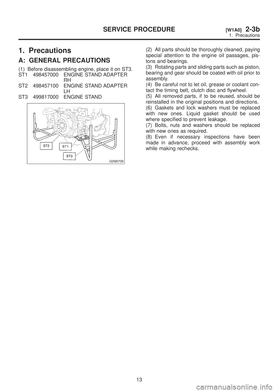
(1) Before disassembling engine, place it on ST3.
ST1 498457000 ENGINE STAND ADAPTER
RH
ST2 498457100 ENGINE STAND ADAPTER
LH
ST3 499817000 ENGINE STAND
G2M0709
(2) All parts should be thoroughly cleaned, paying
special attention to the engine oil passages, pis-
tons and bearings.
(3) Rotating parts and sliding parts such as piston,
bearing and gear should be coated with oil prior to
assembly.
(4) Be careful not to let oil, grease or coolant con-
tact the timing belt, clutch disc and flywheel.
(5) All removed parts, if to be reused, should be
reinstalled in the original positions and directions.
(6) Gaskets and lock washers must be replaced
with new ones. Liquid gasket should be used
where specified to prevent leakage.
(7) Bolts, nuts and washers should be replaced
with new ones as required.
(8) Even if necessary inspections have been
made in advance, proceed with assembly work
while making rechecks.
13
[W1A0]2-3bSERVICE PROCEDURE
1. Precautions
Page 165 of 1456

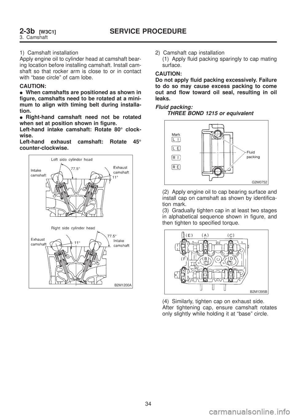
1) Camshaft installation
Apply engine oil to cylinder head at camshaft bear-
ing location before installing camshaft. Install cam-
shaft so that rocker arm is close to or in contact
with ªbase circleº of cam lobe.
CAUTION:
IWhen camshafts are positioned as shown in
figure, camshafts need to be rotated at a mini-
mum to align with timing belt during installa-
tion.
IRight-hand camshaft need not be rotated
when set at position shown in figure.
Left-hand intake camshaft: Rotate 80É clock-
wise.
Left-hand exhaust camshaft: Rotate 45É
counter-clockwise.
B2M1200A
2) Camshaft cap installation
(1) Apply fluid packing sparingly to cap mating
surface.
CAUTION:
Do not apply fluid packing excessively. Failure
to do so may cause excess packing to come
out and flow toward oil seal, resulting in oil
leaks.
Fluid packing:
THREE BOND 1215 or equivalent
G2M0752
(2) Apply engine oil to cap bearing surface and
install cap on camshaft as shown by identifica-
tion mark.
(3) Gradually tighten cap in at least two stages
in alphabetical sequence shown in figure, and
then tighten to specified torque.
B2M1395B
(4) Similarly, tighten cap on exhaust side.
After tightening cap, ensure camshaft rotates
only slightly while holding it at ªbaseº circle.
34
2-3b[W3C1]SERVICE PROCEDURE
3. Camshaft