Page 1223 of 1456
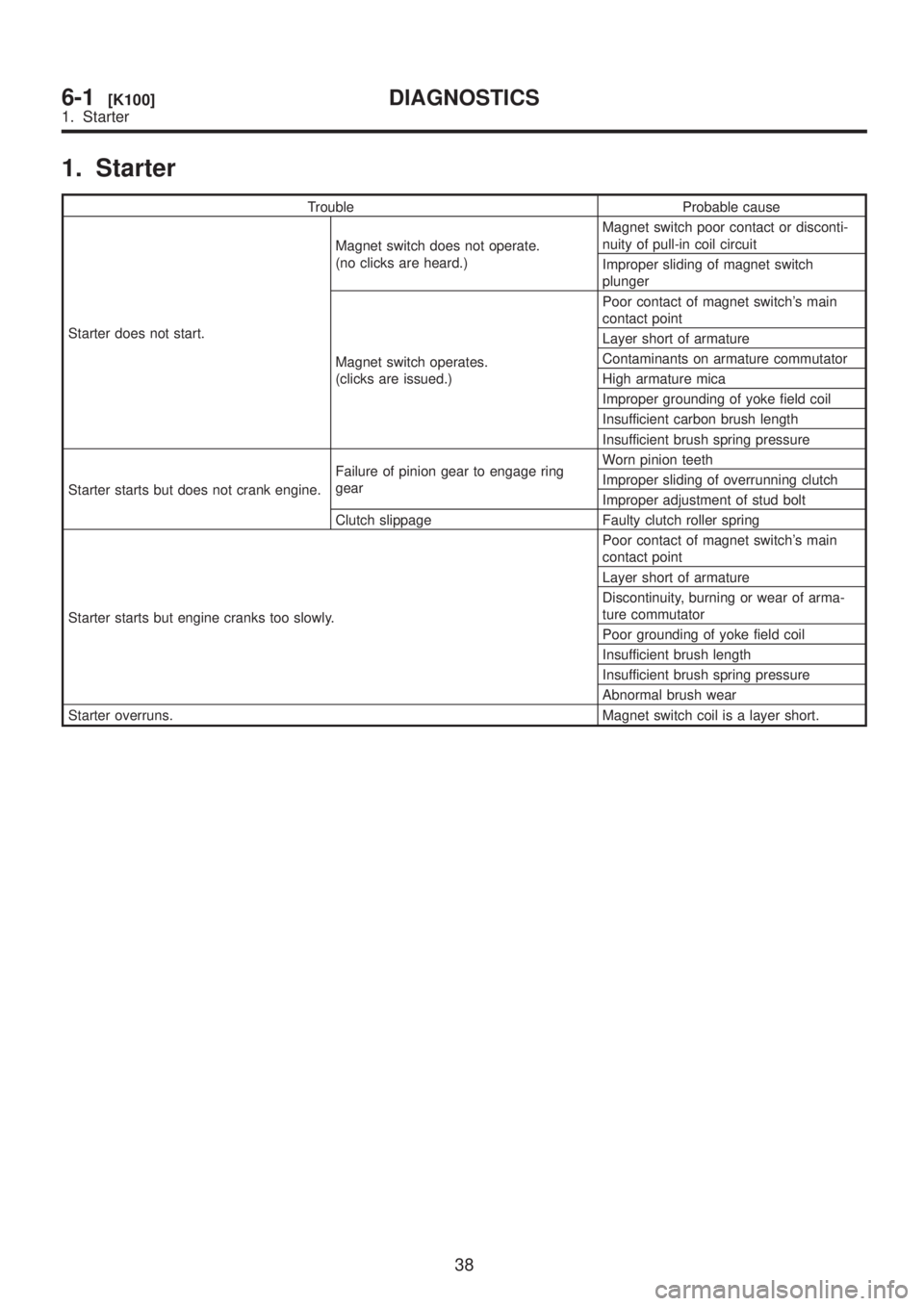
1. Starter
Trouble Probable cause
Starter does not start.Magnet switch does not operate.
(no clicks are heard.)Magnet switch poor contact or disconti-
nuity of pull-in coil circuit
Improper sliding of magnet switch
plunger
Magnet switch operates.
(clicks are issued.)Poor contact of magnet switch's main
contact point
Layer short of armature
Contaminants on armature commutator
High armature mica
Improper grounding of yoke field coil
Insufficient carbon brush length
Insufficient brush spring pressure
Starter starts but does not crank engine.Failure of pinion gear to engage ring
gearWorn pinion teeth
Improper sliding of overrunning clutch
Improper adjustment of stud bolt
Clutch slippage Faulty clutch roller spring
Starter starts but engine cranks too slowly.Poor contact of magnet switch's main
contact point
Layer short of armature
Discontinuity, burning or wear of arma-
ture commutator
Poor grounding of yoke field coil
Insufficient brush length
Insufficient brush spring pressure
Abnormal brush wear
Starter overruns. Magnet switch coil is a layer short.
38
6-1[K100]DIAGNOSTICS
1. Starter
Page 1226 of 1456
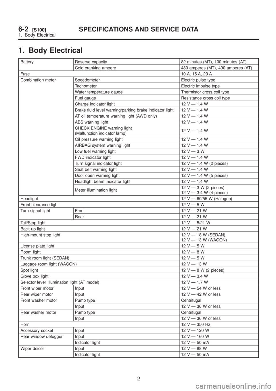
1. Body Electrical
Battery Reserve capacity 82 minutes (MT), 100 minutes (AT)
Cold cranking ampere 430 amperes (MT), 490 amperes (AT)
Fuse10 A, 15 A, 20 A
Combination meter Speedometer Electric pulse type
Tachometer Electric impulse type
Water temperature gauge Thermistor cross coil type
Fuel gauge Resistance cross coil type
Charge indicator light 12 V Ð 1.4 W
Brake fluid level warning/parking brake indicator light 12 V Ð 1.4 W
AT oil temperature warning light (AWD only) 12 V Ð 1.4 W
ABS warning light 12 V Ð 1.4 W
CHECK ENGINE warning light
(Malfunction indicator lamp)12 V Ð 1.4 W
Oil pressure warning light 12 V Ð 1.4 W
AIRBAG system warning light 12 V Ð 1.4 W
Low fuel warning light 12VÐ3W
FWD indicator light 12 V Ð 1.4 W
Turn signal indicator light 12 V Ð 1.4 W (2 pieces)
Seat belt warning light 12 V Ð 1.4 W
Door open warning light 12 V Ð 1.4 W (5 pieces)
Headlight beam indicator light 12 V Ð 1.4 W
Meter illumination light12VÐ3W(2pieces)
12 V Ð 3.4 W (4 pieces)
Headlight12 V Ð 60/55 W (Halogen)
Front clearance light 12VÐ5W
Turn signal light Front 12VÐ21W
Rear 12VÐ21W
Tail/Stop light12 V Ð 5/21 W
Back-up light12VÐ21W
High-mount stop light 12VÐ18W(SEDAN),
12VÐ13W(WAGON)
License plate light 12VÐ5W
Room light12VÐ8W
Trunk room light (SEDAN) 12VÐ5W
Luggage room light (WAGON) 12VÐ13W
Spot light12VÐ8W(2pieces)
Glove box light 12 V Ð 3.4 W
Selector lever illumination light (AT model) 12 V Ð 1.7 W
Front wiper motor Input 12VÐ54Worless
Rear wiper motor Input 12VÐ42Worless
Front washer motor Pump type Centrifugal
Input 12VÐ36Worless
Rear washer motor Pump type Centrifugal
Input 12VÐ36Worless
Horn12 V Ð 350 Hz
Accessory socket Input 12 V Ð 120 W
Rear window defogger Input 12 V Ð 160 W
Indicator light 12VÐ50mA
Wiper deicer Input 12VÐ88W
Indicator light 12VÐ50mA
2
6-2[S100]SPECIFICATIONS AND SERVICE DATA
1. Body Electrical
Page 1231 of 1456
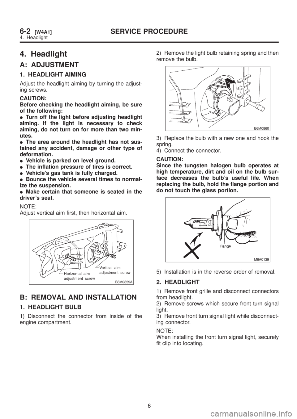
4. Headlight
A: ADJUSTMENT
1. HEADLIGHT AIMING
Adjust the headlight aiming by turning the adjust-
ing screws.
CAUTION:
Before checking the headlight aiming, be sure
of the following:
ITurn off the light before adjusting headlight
aiming. If the light is necessary to check
aiming, do not turn on for more than two min-
utes.
IThe area around the headlight has not sus-
tained any accident, damage or other type of
deformation.
IVehicle is parked on level ground.
IThe inflation pressure of tires is correct.
IVehicle's gas tank is fully charged.
IBounce the vehicle several times to normal-
ize the suspension.
IMake certain that someone is seated in the
driver's seat.
NOTE:
Adjust vertical aim first, then horizontal aim.
B6M0859A
B: REMOVAL AND INSTALLATION
1. HEADLIGHT BULB
1) Disconnect the connector from inside of the
engine compartment.2) Remove the light bulb retaining spring and then
remove the bulb.
B6M0860
3) Replace the bulb with a new one and hook the
spring.
4) Connect the connector.
CAUTION:
Since the tungsten halogen bulb operates at
high temperature, dirt and oil on the bulb sur-
face decreases the bulb's useful life. When
replacing the bulb, hold the flange portion and
do not touch the glass portion.
M6A0139
5) Installation is in the reverse order of removal.
2. HEADLIGHT
1) Remove front grille and disconnect connectors
from headlight.
2) Remove screws which secure front turn signal
light.
3) Remove front turn signal light while disconnect-
ing connector.
NOTE:
When installing the front turn signal light, securely
fit clip into locating.
6
6-2[W4A1]SERVICE PROCEDURE
4. Headlight
Page 1240 of 1456
![SUBARU LEGACY 1999 Service Repair Manual 7. Turn Signal and Hazard
Warning Light
A: REMOVAL AND INSTALLATION
1. FRONT TURN SIGNAL LIGHT
Remove and install front turn signal light. <Ref. to
6-2 [W4B2].>
NOTE:
The front turn signal light is un SUBARU LEGACY 1999 Service Repair Manual 7. Turn Signal and Hazard
Warning Light
A: REMOVAL AND INSTALLATION
1. FRONT TURN SIGNAL LIGHT
Remove and install front turn signal light. <Ref. to
6-2 [W4B2].>
NOTE:
The front turn signal light is un](/manual-img/17/57435/w960_57435-1239.png)
7. Turn Signal and Hazard
Warning Light
A: REMOVAL AND INSTALLATION
1. FRONT TURN SIGNAL LIGHT
Remove and install front turn signal light.
6-2 [W4B2].>
NOTE:
The front turn signal light is united with headlight
assembly.
2. REAR COMBINATION LIGHT
Remove and install rear combination light.
6-2 [W6A1].>
3. COMBINATION SWITCH
Remove and install combination switch.
6-2 [W4B3].>
4. HAZARD SWITCH
1) Remove center panel from instrument panel.
2) Disconnect connector of hazard switch from
body harness.
3) Remove hazard switch from center panel.
B6M0063
4) Installation is in the reverse order of removal.
5. TURN SIGNAL AND HAZARD UNIT
1) Remove instrument panel lower cover.
2) Remove engine hood opener lever bracket.
3) Disconnect connector of turn signal and hazard
unit.4) Remove screw, and then remove turn signal
and hazard unit from bracket.
B6M0343A
5) Installation is in the reverse order of removal.
B: DISASSEMBLY AND ASSEMBLY
1. COMBINATION SWITCH
Disassemble and assemble combination switch.
C: INSPECTION
1. COMBINATION SWITCH (ON-CAR)
1) Remove instrument panel lower cover.
2) Remove lower column cover.
3) Unfasten holddown clip which secures harness,
and disconnect connectors from body harness.
4) Move combination switch to respective posi-
tions and check continuity between terminals.
B6M0702
14
6-2[W7A1]SERVICE PROCEDURE
7. Turn Signal and Hazard Warning Light
Page 1247 of 1456
NOTE:
Remove metal sludge from the wiper arm fixture
before installing it.
Tightening torque:
20
±3 N´m (2.0±0.3 kg-m, 14.5±2.2 ft-lb)
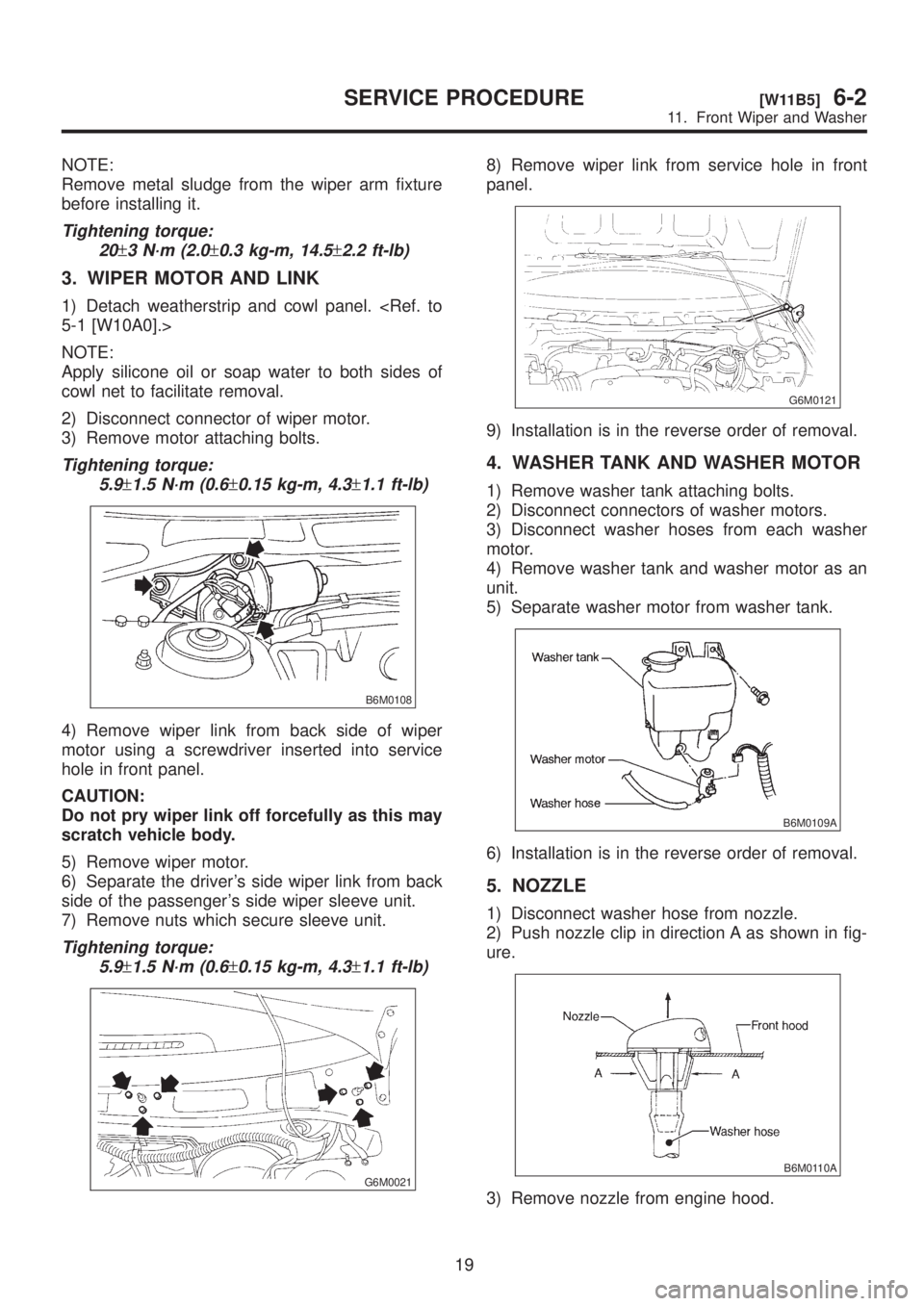
3. WIPER MOTOR AND LINK
1) Detach weatherstrip and cowl panel.
5-1 [W10A0].>
NOTE:
Apply silicone oil or soap water to both sides of
cowl net to facilitate removal.
2) Disconnect connector of wiper motor.
3) Remove motor attaching bolts.
Tightening torque:
5.9
±1.5 N´m (0.6±0.15 kg-m, 4.3±1.1 ft-lb)
B6M0108
4) Remove wiper link from back side of wiper
motor using a screwdriver inserted into service
hole in front panel.
CAUTION:
Do not pry wiper link off forcefully as this may
scratch vehicle body.
5) Remove wiper motor.
6) Separate the driver's side wiper link from back
side of the passenger's side wiper sleeve unit.
7) Remove nuts which secure sleeve unit.
Tightening torque:
5.9
±1.5 N´m (0.6±0.15 kg-m, 4.3±1.1 ft-lb)
G6M0021
8) Remove wiper link from service hole in front
panel.
G6M0121
9) Installation is in the reverse order of removal.
4. WASHER TANK AND WASHER MOTOR
1) Remove washer tank attaching bolts.
2) Disconnect connectors of washer motors.
3) Disconnect washer hoses from each washer
motor.
4) Remove washer tank and washer motor as an
unit.
5) Separate washer motor from washer tank.
B6M0109A
6) Installation is in the reverse order of removal.
5. NOZZLE
1) Disconnect washer hose from nozzle.
2) Push nozzle clip in direction A as shown in fig-
ure.
B6M0110A
3) Remove nozzle from engine hood.
19
[W11B5]6-2SERVICE PROCEDURE
11. Front Wiper and Washer
Page 1253 of 1456
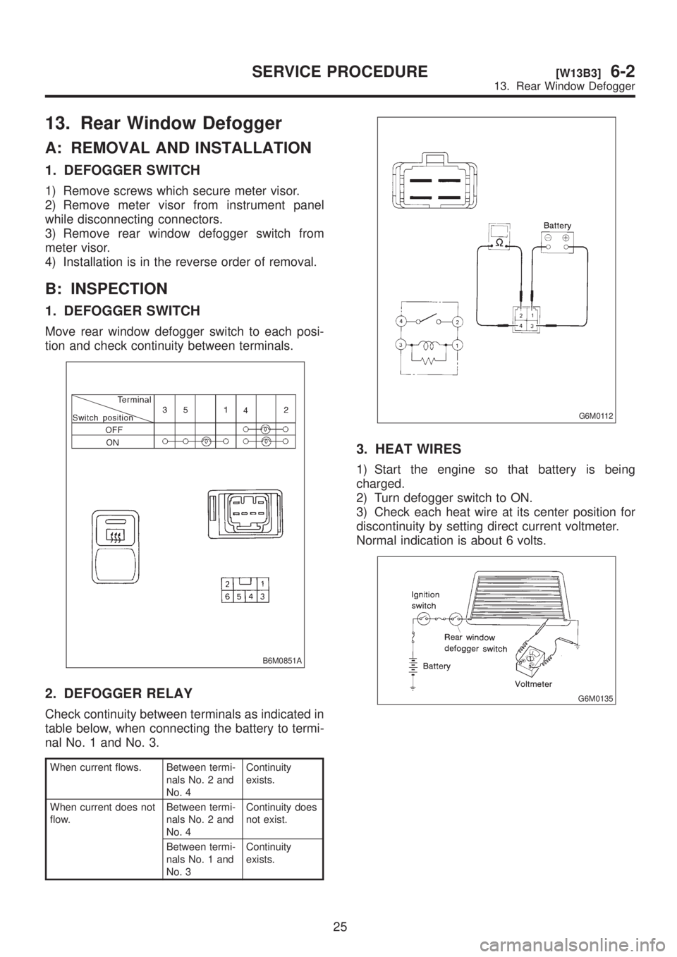
13. Rear Window Defogger
A: REMOVAL AND INSTALLATION
1. DEFOGGER SWITCH
1) Remove screws which secure meter visor.
2) Remove meter visor from instrument panel
while disconnecting connectors.
3) Remove rear window defogger switch from
meter visor.
4) Installation is in the reverse order of removal.
B: INSPECTION
1. DEFOGGER SWITCH
Move rear window defogger switch to each posi-
tion and check continuity between terminals.
B6M0851A
2. DEFOGGER RELAY
Check continuity between terminals as indicated in
table below, when connecting the battery to termi-
nal No. 1 and No. 3.
When current flows. Between termi-
nals No. 2 and
No. 4Continuity
exists.
When current does not
flow.Between termi-
nals No. 2 and
No. 4Continuity does
not exist.
Between termi-
nals No. 1 and
No. 3Continuity
exists.
G6M0112
3. HEAT WIRES
1) Start the engine so that battery is being
charged.
2) Turn defogger switch to ON.
3) Check each heat wire at its center position for
discontinuity by setting direct current voltmeter.
Normal indication is about 6 volts.
G6M0135
25
[W13B3]6-2SERVICE PROCEDURE
13. Rear Window Defogger
Page 1256 of 1456
B: BULB REPLACEMENT
B6M0761C
(1) Tachometer and temperature
gauge illumination
(2) Oil pressure
(3) CHECK ENGINE (Malfunction
Indicator Light)
(4) Tachometer illumination
(5) Turn signal (RH)
(6) Headlight beam(7) Door open (Front-Right)
(8) Seat belt
(9) Door open (Front-Left)
(10) Door open (Rear-Right)
(11) Door open (Rear-Left)
(12) Rear gate open (Wagon)
(13) Turn signal (LH)
(14) Speedometer illumination(15) Speedometer and fuel gauge
illumination
(16) Low fuel
(17) Charge
(18) Brake fluid level/parking brake
(19) FWD
(20) AT oil temperature
(21) ABS
28
6-2[W14B0]SERVICE PROCEDURE
14. Combination Meter
Page 1258 of 1456
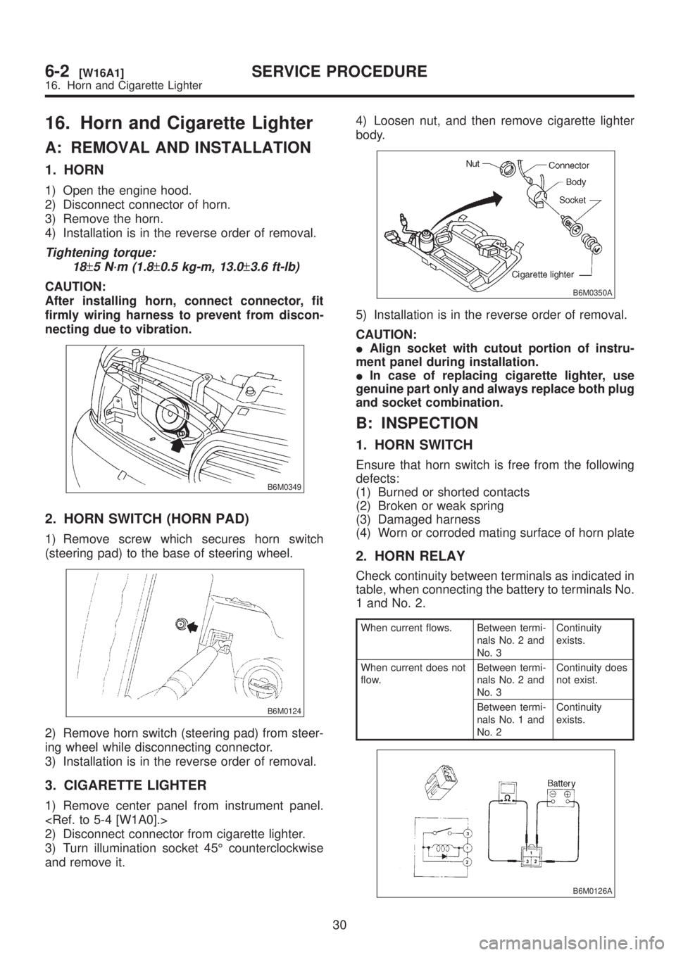
16. Horn and Cigarette Lighter
A: REMOVAL AND INSTALLATION
1. HORN
1) Open the engine hood.
2) Disconnect connector of horn.
3) Remove the horn.
4) Installation is in the reverse order of removal.
Tightening torque:
18
±5 N´m (1.8±0.5 kg-m, 13.0±3.6 ft-lb)
CAUTION:
After installing horn, connect connector, fit
firmly wiring harness to prevent from discon-
necting due to vibration.
B6M0349
2. HORN SWITCH (HORN PAD)
1) Remove screw which secures horn switch
(steering pad) to the base of steering wheel.
B6M0124
2) Remove horn switch (steering pad) from steer-
ing wheel while disconnecting connector.
3) Installation is in the reverse order of removal.
3. CIGARETTE LIGHTER
1) Remove center panel from instrument panel.
2) Disconnect connector from cigarette lighter.
3) Turn illumination socket 45É counterclockwise
and remove it.4) Loosen nut, and then remove cigarette lighter
body.
B6M0350A
5) Installation is in the reverse order of removal.
CAUTION:
IAlign socket with cutout portion of instru-
ment panel during installation.
IIn case of replacing cigarette lighter, use
genuine part only and always replace both plug
and socket combination.
B: INSPECTION
1. HORN SWITCH
Ensure that horn switch is free from the following
defects:
(1) Burned or shorted contacts
(2) Broken or weak spring
(3) Damaged harness
(4) Worn or corroded mating surface of horn plate
2. HORN RELAY
Check continuity between terminals as indicated in
table, when connecting the battery to terminals No.
1 and No. 2.
When current flows. Between termi-
nals No. 2 and
No. 3Continuity
exists.
When current does not
flow.Between termi-
nals No. 2 and
No. 3Continuity does
not exist.
Between termi-
nals No. 1 and
No. 2Continuity
exists.
B6M0126A
30
6-2[W16A1]SERVICE PROCEDURE
16. Horn and Cigarette Lighter