1999 SUBARU LEGACY engine
[x] Cancel search: enginePage 953 of 1456
B: REMOVAL
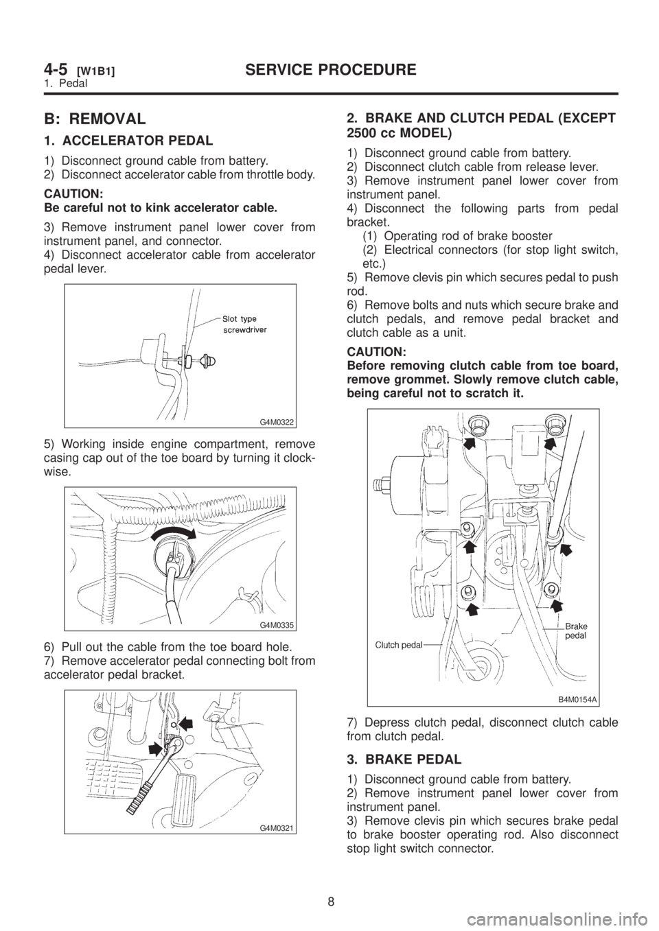
1. ACCELERATOR PEDAL
1) Disconnect ground cable from battery.
2) Disconnect accelerator cable from throttle body.
CAUTION:
Be careful not to kink accelerator cable.
3) Remove instrument panel lower cover from
instrument panel, and connector.
4) Disconnect accelerator cable from accelerator
pedal lever.
G4M0322
5) Working inside engine compartment, remove
casing cap out of the toe board by turning it clock-
wise.
G4M0335
6) Pull out the cable from the toe board hole.
7) Remove accelerator pedal connecting bolt from
accelerator pedal bracket.
G4M0321
2. BRAKE AND CLUTCH PEDAL (EXCEPT
2500 cc MODEL)
1) Disconnect ground cable from battery.
2) Disconnect clutch cable from release lever.
3) Remove instrument panel lower cover from
instrument panel.
4) Disconnect the following parts from pedal
bracket.
(1) Operating rod of brake booster
(2) Electrical connectors (for stop light switch,
etc.)
5) Remove clevis pin which secures pedal to push
rod.
6) Remove bolts and nuts which secure brake and
clutch pedals, and remove pedal bracket and
clutch cable as a unit.
CAUTION:
Before removing clutch cable from toe board,
remove grommet. Slowly remove clutch cable,
being careful not to scratch it.
B4M0154A
7) Depress clutch pedal, disconnect clutch cable
from clutch pedal.
3. BRAKE PEDAL
1) Disconnect ground cable from battery.
2) Remove instrument panel lower cover from
instrument panel.
3) Remove clevis pin which secures brake pedal
to brake booster operating rod. Also disconnect
stop light switch connector.
8
4-5[W1B1]SERVICE PROCEDURE
1. Pedal
Page 959 of 1456
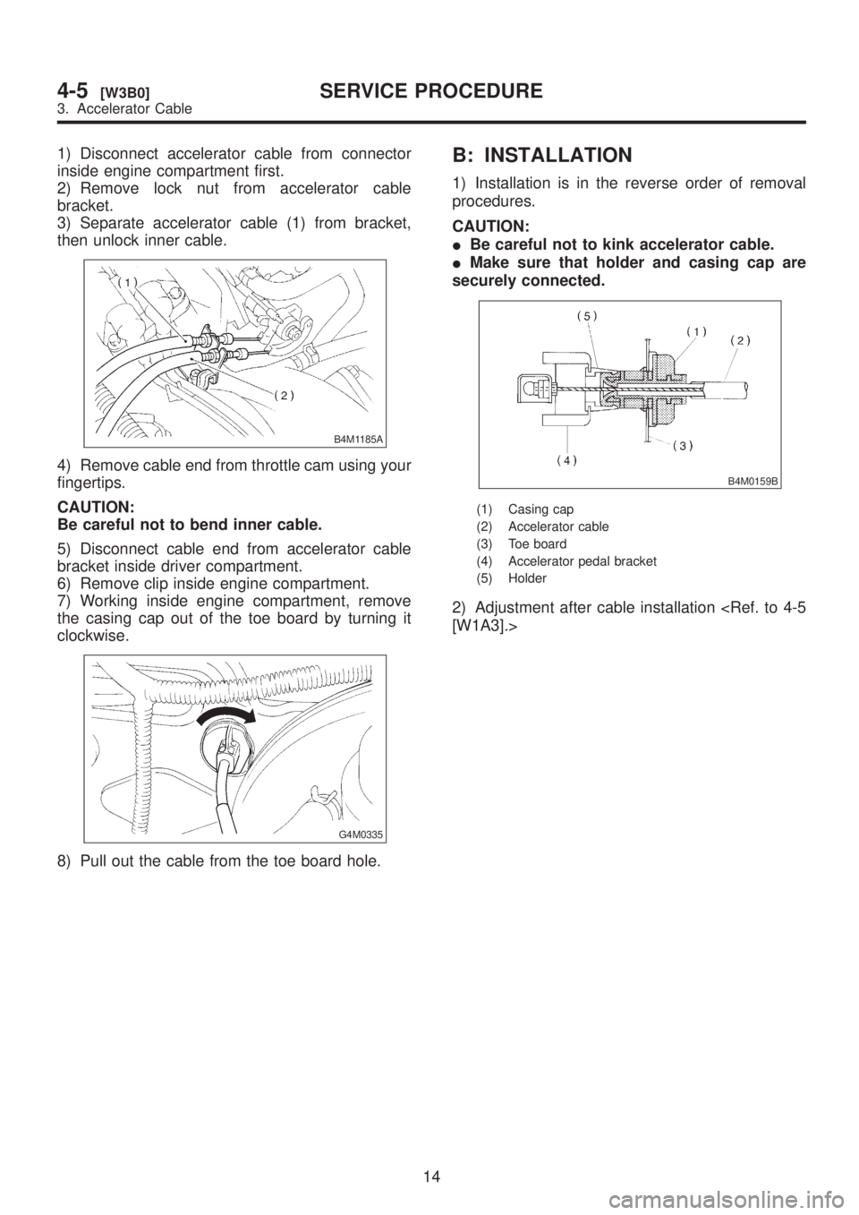
1) Disconnect accelerator cable from connector
inside engine compartment first.
2) Remove lock nut from accelerator cable
bracket.
3) Separate accelerator cable (1) from bracket,
then unlock inner cable.
B4M1185A
4) Remove cable end from throttle cam using your
fingertips.
CAUTION:
Be careful not to bend inner cable.
5) Disconnect cable end from accelerator cable
bracket inside driver compartment.
6) Remove clip inside engine compartment.
7) Working inside engine compartment, remove
the casing cap out of the toe board by turning it
clockwise.
G4M0335
8) Pull out the cable from the toe board hole.
B: INSTALLATION
1) Installation is in the reverse order of removal
procedures.
CAUTION:
IBe careful not to kink accelerator cable.
IMake sure that holder and casing cap are
securely connected.
B4M0159B
(1) Casing cap
(2) Accelerator cable
(3) Toe board
(4) Accelerator pedal bracket
(5) Holder
2) Adjustment after cable installation
14
4-5[W3B0]SERVICE PROCEDURE
3. Accelerator Cable
Page 967 of 1456
1. Precaution
A: SUPPLEMENTAL RESTRAINT
SYSTEM ªAIRBAGº
CAUTION:
IAll Airbag system wiring harness and con-
nectors are colored yellow. Do not use electri-
cal test equipment on these circuit.
IBe careful not to damage Airbag system wir-
ing harness when servicing the instrument
panel, heater unit, blower motor and control
unit.
Airbag system wiring harness is routed near the
instrument panel, heater unit, blower motor and
control unit.
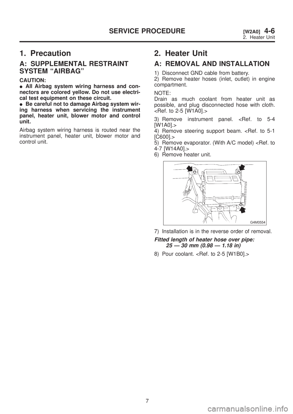
2. Heater Unit
A: REMOVAL AND INSTALLATION
1) Disconnect GND cable from battery.
2) Remove heater hoses (inlet, outlet) in engine
compartment.
NOTE:
Drain as much coolant from heater unit as
possible, and plug disconnected hose with cloth.
3) Remove instrument panel.
4) Remove steering support beam.
5) Remove evaporator. (With A/C model)
6) Remove heater unit.
G4M0554
7) Installation is in the reverse order of removal.
Fitted length of heater hose over pipe:
25 Ð 30 mm (0.98 Ð 1.18 in)
8) Pour coolant.
7
[W2A0]4-6SERVICE PROCEDURE
2. Heater Unit
Page 968 of 1456
1. Precaution
A: SUPPLEMENTAL RESTRAINT
SYSTEM ªAIRBAGº
CAUTION:
IAll Airbag system wiring harness and con-
nectors are colored yellow. Do not use electri-
cal test equipment on these circuit.
IBe careful not to damage Airbag system wir-
ing harness when servicing the instrument
panel, heater unit, blower motor and control
unit.
Airbag system wiring harness is routed near the
instrument panel, heater unit, blower motor and
control unit.
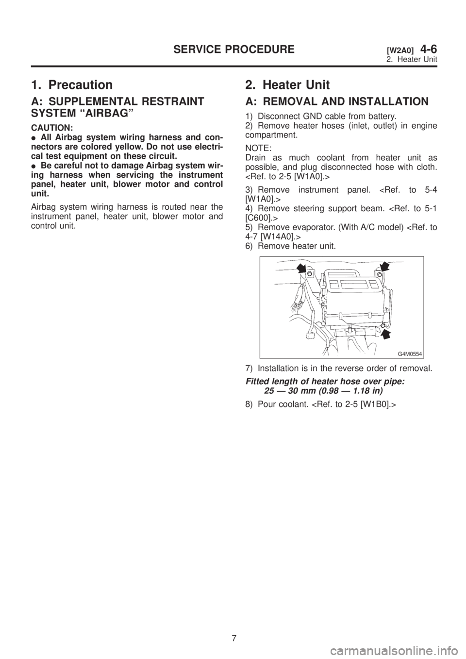
2. Heater Unit
A: REMOVAL AND INSTALLATION
1) Disconnect GND cable from battery.
2) Remove heater hoses (inlet, outlet) in engine
compartment.
NOTE:
Drain as much coolant from heater unit as
possible, and plug disconnected hose with cloth.
3) Remove instrument panel.
4) Remove steering support beam.
5) Remove evaporator. (With A/C model)
6) Remove heater unit.
G4M0554
7) Installation is in the reverse order of removal.
Fitted length of heater hose over pipe:
25 Ð 30 mm (0.98 Ð 1.18 in)
8) Pour coolant.
7
[W2A0]4-6SERVICE PROCEDURE
2. Heater Unit
Page 990 of 1456
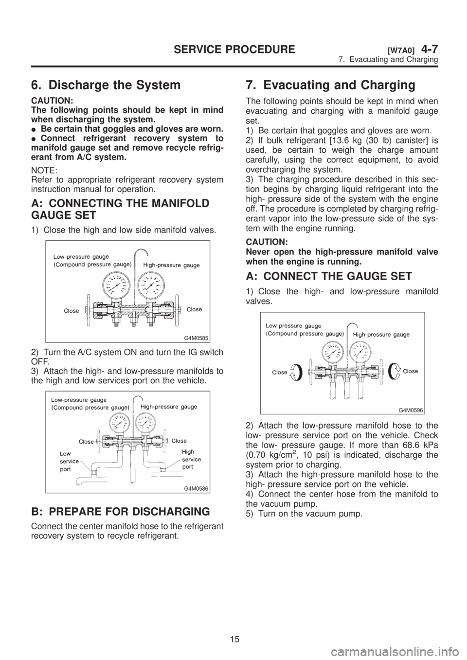
6. Discharge the System
CAUTION:
The following points should be kept in mind
when discharging the system.
IBe certain that goggles and gloves are worn.
IConnect refrigerant recovery system to
manifold gauge set and remove recycle refrig-
erant from A/C system.
NOTE:
Refer to appropriate refrigerant recovery system
instruction manual for operation.
A: CONNECTING THE MANIFOLD
GAUGE SET
1) Close the high and low side manifold valves.
G4M0585
2) Turn the A/C system ON and turn the IG switch
OFF.
3) Attach the high- and low-pressure manifolds to
the high and low services port on the vehicle.
G4M0586
B: PREPARE FOR DISCHARGING
Connect the center manifold hose to the refrigerant
recovery system to recycle refrigerant.
7. Evacuating and Charging
The following points should be kept in mind when
evacuating and charging with a manifold gauge
set.
1) Be certain that goggles and gloves are worn.
2) If bulk refrigerant [13.6 kg (30 lb) canister] is
used, be certain to weigh the charge amount
carefully, using the correct equipment, to avoid
overcharging the system.
3) The charging procedure described in this sec-
tion begins by charging liquid refrigerant into the
high- pressure side of the system with the engine
off. The procedure is completed by charging refrig-
erant vapor into the low-pressure side of the sys-
tem with the engine running.
CAUTION:
Never open the high-pressure manifold valve
when the engine is running.
A: CONNECT THE GAUGE SET
1) Close the high- and low-pressure manifold
valves.
G4M0596
2) Attach the low-pressure manifold hose to the
low- pressure service port on the vehicle. Check
the low- pressure gauge. If more than 68.6 kPa
(0.70 kg/cm
2, 10 psi) is indicated, discharge the
system prior to charging.
3) Attach the high-pressure manifold hose to the
high- pressure service port on the vehicle.
4) Connect the center hose from the manifold to
the vacuum pump.
5) Turn on the vacuum pump.
15
[W7A0]4-7SERVICE PROCEDURE
7. Evacuating and Charging
Page 991 of 1456

6. Discharge the System
CAUTION:
The following points should be kept in mind
when discharging the system.
IBe certain that goggles and gloves are worn.
IConnect refrigerant recovery system to
manifold gauge set and remove recycle refrig-
erant from A/C system.
NOTE:
Refer to appropriate refrigerant recovery system
instruction manual for operation.
A: CONNECTING THE MANIFOLD
GAUGE SET
1) Close the high and low side manifold valves.
G4M0585
2) Turn the A/C system ON and turn the IG switch
OFF.
3) Attach the high- and low-pressure manifolds to
the high and low services port on the vehicle.
G4M0586
B: PREPARE FOR DISCHARGING
Connect the center manifold hose to the refrigerant
recovery system to recycle refrigerant.
7. Evacuating and Charging
The following points should be kept in mind when
evacuating and charging with a manifold gauge
set.
1) Be certain that goggles and gloves are worn.
2) If bulk refrigerant [13.6 kg (30 lb) canister] is
used, be certain to weigh the charge amount
carefully, using the correct equipment, to avoid
overcharging the system.
3) The charging procedure described in this sec-
tion begins by charging liquid refrigerant into the
high- pressure side of the system with the engine
off. The procedure is completed by charging refrig-
erant vapor into the low-pressure side of the sys-
tem with the engine running.
CAUTION:
Never open the high-pressure manifold valve
when the engine is running.
A: CONNECT THE GAUGE SET
1) Close the high- and low-pressure manifold
valves.
G4M0596
2) Attach the low-pressure manifold hose to the
low- pressure service port on the vehicle. Check
the low- pressure gauge. If more than 68.6 kPa
(0.70 kg/cm
2, 10 psi) is indicated, discharge the
system prior to charging.
3) Attach the high-pressure manifold hose to the
high- pressure service port on the vehicle.
4) Connect the center hose from the manifold to
the vacuum pump.
5) Turn on the vacuum pump.
15
[W7A0]4-7SERVICE PROCEDURE
7. Evacuating and Charging
Page 993 of 1456
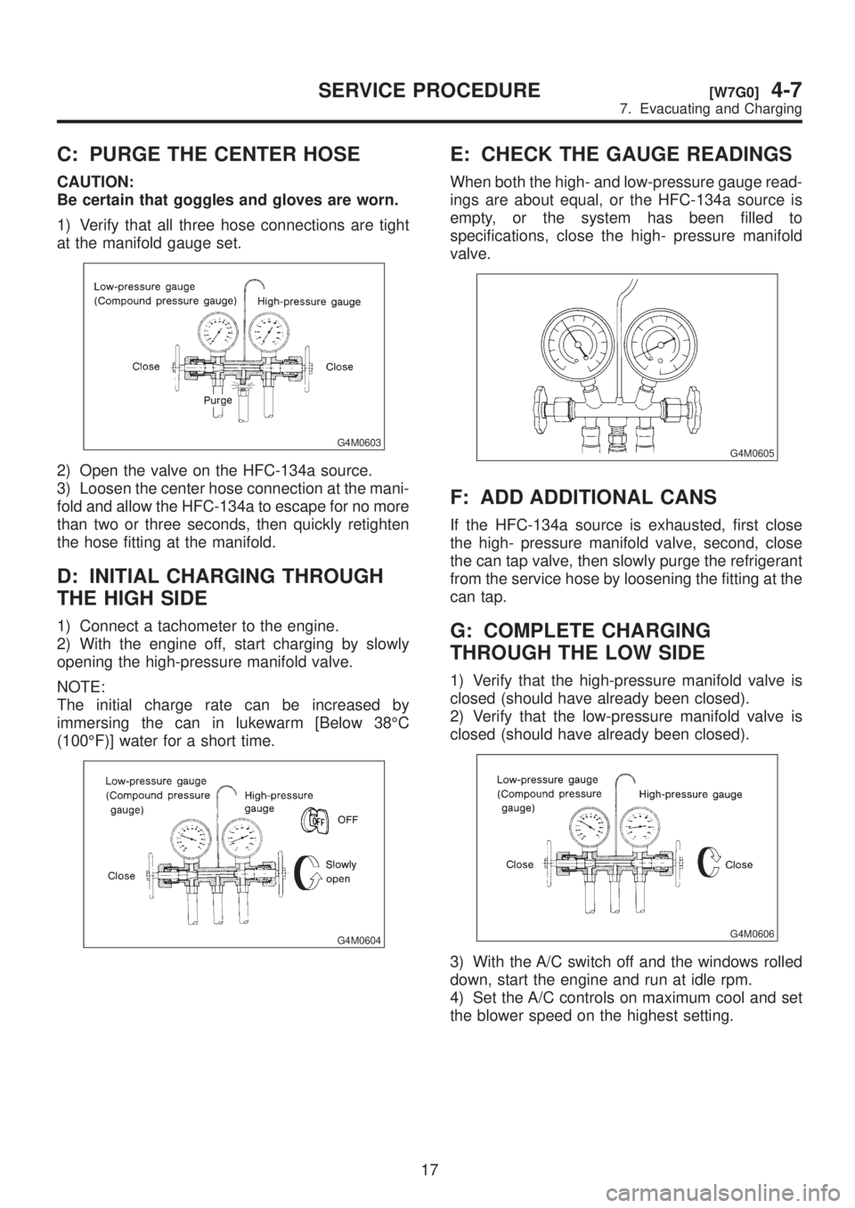
C: PURGE THE CENTER HOSE
CAUTION:
Be certain that goggles and gloves are worn.
1) Verify that all three hose connections are tight
at the manifold gauge set.
G4M0603
2) Open the valve on the HFC-134a source.
3) Loosen the center hose connection at the mani-
fold and allow the HFC-134a to escape for no more
than two or three seconds, then quickly retighten
the hose fitting at the manifold.
D: INITIAL CHARGING THROUGH
THE HIGH SIDE
1) Connect a tachometer to the engine.
2) With the engine off, start charging by slowly
opening the high-pressure manifold valve.
NOTE:
The initial charge rate can be increased by
immersing the can in lukewarm [Below 38ÉC
(100ÉF)] water for a short time.
G4M0604
E: CHECK THE GAUGE READINGS
When both the high- and low-pressure gauge read-
ings are about equal, or the HFC-134a source is
empty, or the system has been filled to
specifications, close the high- pressure manifold
valve.
G4M0605
F: ADD ADDITIONAL CANS
If the HFC-134a source is exhausted, first close
the high- pressure manifold valve, second, close
the can tap valve, then slowly purge the refrigerant
from the service hose by loosening the fitting at the
can tap.
G: COMPLETE CHARGING
THROUGH THE LOW SIDE
1) Verify that the high-pressure manifold valve is
closed (should have already been closed).
2) Verify that the low-pressure manifold valve is
closed (should have already been closed).
G4M0606
3) With the A/C switch off and the windows rolled
down, start the engine and run at idle rpm.
4) Set the A/C controls on maximum cool and set
the blower speed on the highest setting.
17
[W7G0]4-7SERVICE PROCEDURE
7. Evacuating and Charging
Page 994 of 1456

5) Quickly turn the A/C switch on-off-on-off a few
times to prevent initial compressor damage due to
ªload shock.º Finish this operation with the A/C
switch in the ON position.
G4M0607
6) Raise engine rpm to approximately 1,500 rpm.
H: CHARGE THE SYSTEM
1) With the refrigerant source connected and the
service hose purged, slowly open the low-pressure
manifold valve, while checking the low-pressure
gauge reading.
CAUTION:
The refrigerant source must be positioned for
vapor (valve up).
G4M0608
2) Keep the low side pressure below 276 kPa
(2.81 kg/cm2, 40 psi) by using the low-pressure
manifold valve to regulate the flow of refrigerant
into the system.
3) When the system is fully charged, close the
low- pressure manifold valve.
4) Close the valve at the refrigerant source.
IRefrigerant capacity
Unit: kg (lb)
Refrigerant Minimum Maximum
HFC-134a 0.55 (1.21) 0.65 (1.43)
I: COMPLETE ALL SYSTEM
CHECKS
1) Evaluate the system performance.
CAUTION:
IAlways perform leak checking in an environ-
ment free of refrigerant pollution.
IDo not disconnect the high- or low-pressure
hoses from the vehicle before leak checking.
J: DISCONNECT THE MANIFOLD
GAUGE SET
Remove the high- or low-pressure hoses from the
service ports and install the service port caps.
18
4-7[W7H0]SERVICE PROCEDURE
7. Evacuating and Charging