1999 SUBARU LEGACY engine
[x] Cancel search: enginePage 995 of 1456
8. Leak Testing
A: INSPECTION
The following points should be kept in mind when
conducting a refrigerant leak test.
1) The A/C system to be tested must have an
adequate refrigerant charge to begin with.
2) The area where the leak test is conducted must
be free of wind and drafts, with still air being the
ideal condition.
3) The atmosphere where the leak test is con-
ducted must be free of refrigerant contamination.
4) Operate the A/C system for approx. 10 minutes,
then turn the engine off an begin the leak test.
5) Refrigerant gas is heavier than air, therefore
always hold the probe below the connection being
tested.
6) When checking for a leak along a length of
hose or tube, the leak detector probe must be
moved slowly, approx. 25 mm (1 in) per second
making sure probe does not come in contact with
the component being tested.
7) When checking for a leak at a certain point, the
leak detector probe must be held at that point for
at least 5 seconds.
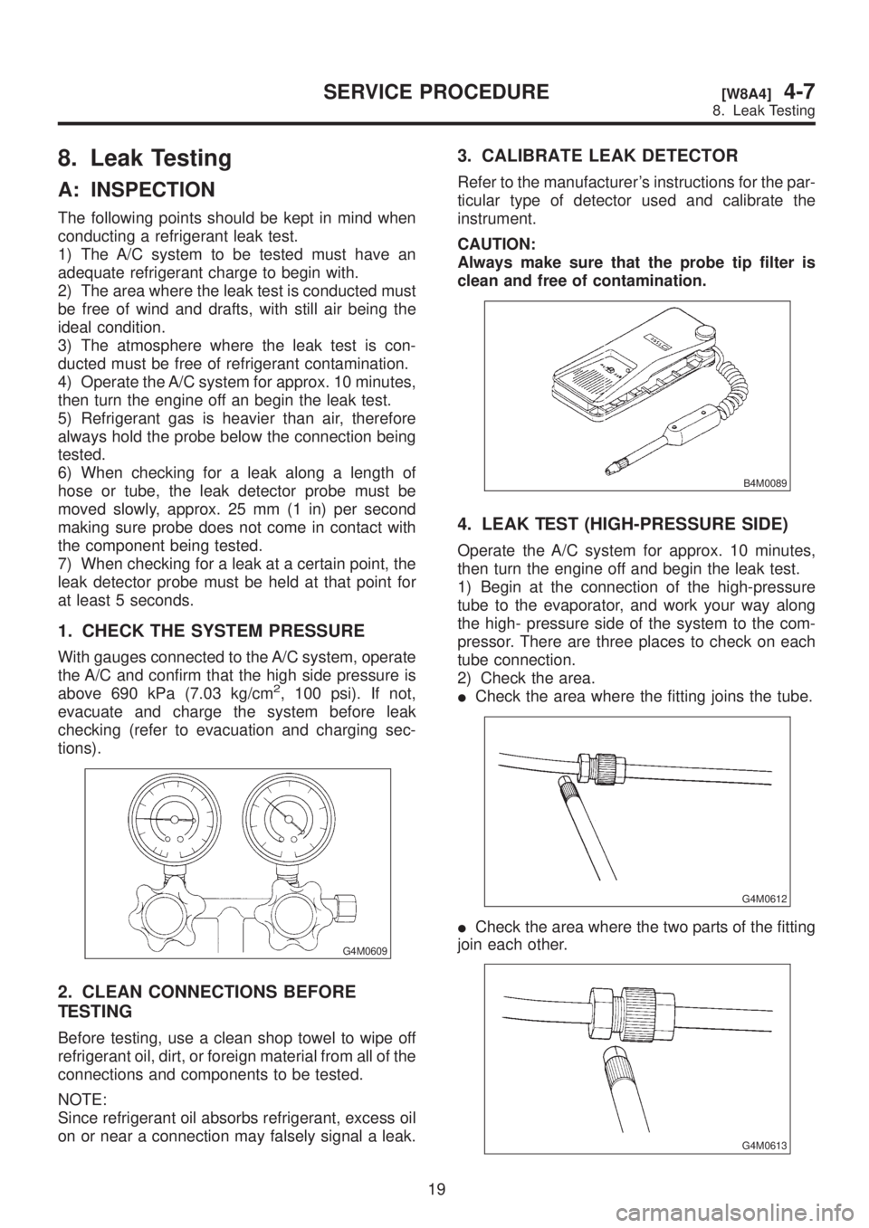
1. CHECK THE SYSTEM PRESSURE
With gauges connected to the A/C system, operate
the A/C and confirm that the high side pressure is
above 690 kPa (7.03 kg/cm
2, 100 psi). If not,
evacuate and charge the system before leak
checking (refer to evacuation and charging sec-
tions).
G4M0609
2. CLEAN CONNECTIONS BEFORE
TESTING
Before testing, use a clean shop towel to wipe off
refrigerant oil, dirt, or foreign material from all of the
connections and components to be tested.
NOTE:
Since refrigerant oil absorbs refrigerant, excess oil
on or near a connection may falsely signal a leak.
3. CALIBRATE LEAK DETECTOR
Refer to the manufacturer's instructions for the par-
ticular type of detector used and calibrate the
instrument.
CAUTION:
Always make sure that the probe tip filter is
clean and free of contamination.
B4M0089
4. LEAK TEST (HIGH-PRESSURE SIDE)
Operate the A/C system for approx. 10 minutes,
then turn the engine off and begin the leak test.
1) Begin at the connection of the high-pressure
tube to the evaporator, and work your way along
the high- pressure side of the system to the com-
pressor. There are three places to check on each
tube connection.
2) Check the area.
ICheck the area where the fitting joins the tube.
G4M0612
ICheck the area where the two parts of the fitting
join each other.
G4M0613
19
[W8A4]4-7SERVICE PROCEDURE
8. Leak Testing
Page 997 of 1456
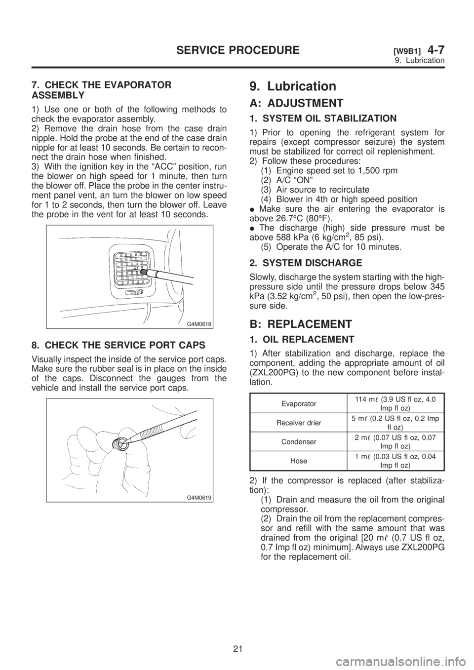
7. CHECK THE EVAPORATOR
ASSEMBLY
1) Use one or both of the following methods to
check the evaporator assembly.
2) Remove the drain hose from the case drain
nipple. Hold the probe at the end of the case drain
nipple for at least 10 seconds. Be certain to recon-
nect the drain hose when finished.
3) With the ignition key in the ªACCº position, run
the blower on high speed for 1 minute, then turn
the blower off. Place the probe in the center instru-
ment panel vent, an turn the blower on low speed
for 1 to 2 seconds, then turn the blower off. Leave
the probe in the vent for at least 10 seconds.
G4M0618
8. CHECK THE SERVICE PORT CAPS
Visually inspect the inside of the service port caps.
Make sure the rubber seal is in place on the inside
of the caps. Disconnect the gauges from the
vehicle and install the service port caps.
G4M0619
9. Lubrication
A: ADJUSTMENT
1. SYSTEM OIL STABILIZATION
1) Prior to opening the refrigerant system for
repairs (except compressor seizure) the system
must be stabilized for correct oil replenishment.
2) Follow these procedures:
(1) Engine speed set to 1,500 rpm
(2) A/C ªONº
(3) Air source to recirculate
(4) Blower in 4th or high speed position
IMake sure the air entering the evaporator is
above 26.7ÉC (80ÉF).
IThe discharge (high) side pressure must be
above 588 kPa (6 kg/cm
2, 85 psi).
(5) Operate the A/C for 10 minutes.
2. SYSTEM DISCHARGE
Slowly, discharge the system starting with the high-
pressure side until the pressure drops below 345
kPa (3.52 kg/cm
2, 50 psi), then open the low-pres-
sure side.
B: REPLACEMENT
1. OIL REPLACEMENT
1) After stabilization and discharge, replace the
component, adding the appropriate amount of oil
(ZXL200PG) to the new component before instal-
lation.
Evaporator11 4 m(3.9 US fl oz, 4.0
Imp fl oz)
Receiver drier5m(0.2 US fl oz, 0.2 Imp
fl oz)
Condenser2m(0.07 US fl oz, 0.07
Imp fl oz)
Hose1m(0.03 US fl oz, 0.04
Imp fl oz)
2) If the compressor is replaced (after stabiliza-
tion):
(1) Drain and measure the oil from the original
compressor.
(2) Drain the oil from the replacement compres-
sor and refill with the same amount that was
drained from the original [20 m(0.7 US fl oz,
0.7 Imp fl oz) minimum]. Always use ZXL200PG
for the replacement oil.
21
[W9B1]4-7SERVICE PROCEDURE
9. Lubrication
Page 998 of 1456
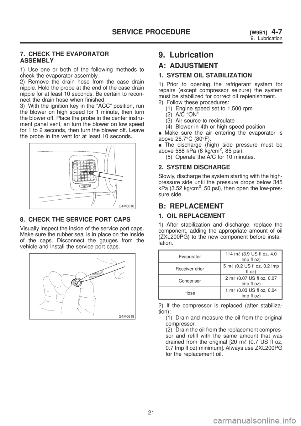
7. CHECK THE EVAPORATOR
ASSEMBLY
1) Use one or both of the following methods to
check the evaporator assembly.
2) Remove the drain hose from the case drain
nipple. Hold the probe at the end of the case drain
nipple for at least 10 seconds. Be certain to recon-
nect the drain hose when finished.
3) With the ignition key in the ªACCº position, run
the blower on high speed for 1 minute, then turn
the blower off. Place the probe in the center instru-
ment panel vent, an turn the blower on low speed
for 1 to 2 seconds, then turn the blower off. Leave
the probe in the vent for at least 10 seconds.
G4M0618
8. CHECK THE SERVICE PORT CAPS
Visually inspect the inside of the service port caps.
Make sure the rubber seal is in place on the inside
of the caps. Disconnect the gauges from the
vehicle and install the service port caps.
G4M0619
9. Lubrication
A: ADJUSTMENT
1. SYSTEM OIL STABILIZATION
1) Prior to opening the refrigerant system for
repairs (except compressor seizure) the system
must be stabilized for correct oil replenishment.
2) Follow these procedures:
(1) Engine speed set to 1,500 rpm
(2) A/C ªONº
(3) Air source to recirculate
(4) Blower in 4th or high speed position
IMake sure the air entering the evaporator is
above 26.7ÉC (80ÉF).
IThe discharge (high) side pressure must be
above 588 kPa (6 kg/cm
2, 85 psi).
(5) Operate the A/C for 10 minutes.
2. SYSTEM DISCHARGE
Slowly, discharge the system starting with the high-
pressure side until the pressure drops below 345
kPa (3.52 kg/cm
2, 50 psi), then open the low-pres-
sure side.
B: REPLACEMENT
1. OIL REPLACEMENT
1) After stabilization and discharge, replace the
component, adding the appropriate amount of oil
(ZXL200PG) to the new component before instal-
lation.
Evaporator11 4 m(3.9 US fl oz, 4.0
Imp fl oz)
Receiver drier5m(0.2 US fl oz, 0.2 Imp
fl oz)
Condenser2m(0.07 US fl oz, 0.07
Imp fl oz)
Hose1m(0.03 US fl oz, 0.04
Imp fl oz)
2) If the compressor is replaced (after stabiliza-
tion):
(1) Drain and measure the oil from the original
compressor.
(2) Drain the oil from the replacement compres-
sor and refill with the same amount that was
drained from the original [20 m(0.7 US fl oz,
0.7 Imp fl oz) minimum]. Always use ZXL200PG
for the replacement oil.
21
[W9B1]4-7SERVICE PROCEDURE
9. Lubrication
Page 999 of 1456
10. Performance Test
A: INSPECTION
1. VEHICLE SET UP
In order to obtain meaningful test results, the
vehicle must be set up to meet the following con-
ditions.
IVehicle in shade
INo wind
IAll vehicle doors closed
IFront windows opened
IHood opened
IEngine speed set at 1,500 rpm.
IA/C ON
ITemperature control lever Ð Maximum cold
IAir source Ð Recirculation
IBlower speed Ð 4th position (High)
IOperate A/C for 10 minutes (Minimum) before
taking measurement.
2. MEASUREMENTS
After 10 minutes (Minimum) of A/C operation and
using accurate test equipment, take the following
measurements (in order).
1) Evaporator intake air temperature at recircula-
tion door.
2) Evaporator discharge air temperature at center
grill.
3) Condenser (Ambient) intake air temperature
measured 0.9 m (3 ft) in front and in line with the
center of the condenser.
4) Suction (Low) side pressure
5) Discharge (High) side pressure
NOTE:
If only one thermometer is available; 1)take the
ambient measurement first; then 2)the intake air;
and 3)discharge air temperature.
22
4-7[W10A1]SERVICE PROCEDURE
10. Performance Test
Page 1017 of 1456
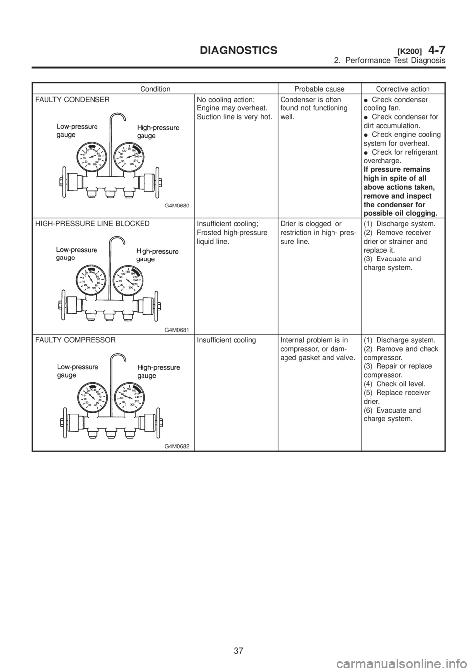
Condition Probable cause Corrective action
FAULTY CONDENSER
G4M0680
No cooling action;
Engine may overheat.
Suction line is very hot.Condenser is often
found not functioning
well.ICheck condenser
cooling fan.
ICheck condenser for
dirt accumulation.
ICheck engine cooling
system for overheat.
ICheck for refrigerant
overcharge.
If pressure remains
high in spite of all
above actions taken,
remove and inspect
the condenser for
possible oil clogging.
HIGH-PRESSURE LINE BLOCKED
G4M0681
Insufficient cooling;
Frosted high-pressure
liquid line.Drier is clogged, or
restriction in high- pres-
sure line.(1) Discharge system.
(2) Remove receiver
drier or strainer and
replace it.
(3) Evacuate and
charge system.
FAULTY COMPRESSOR
G4M0682
Insufficient cooling Internal problem is in
compressor, or dam-
aged gasket and valve.(1) Discharge system.
(2) Remove and check
compressor.
(3) Repair or replace
compressor.
(4) Check oil level.
(5) Replace receiver
drier.
(6) Evacuate and
charge system.
37
[K200]4-7DIAGNOSTICS
2. Performance Test Diagnosis
Page 1026 of 1456
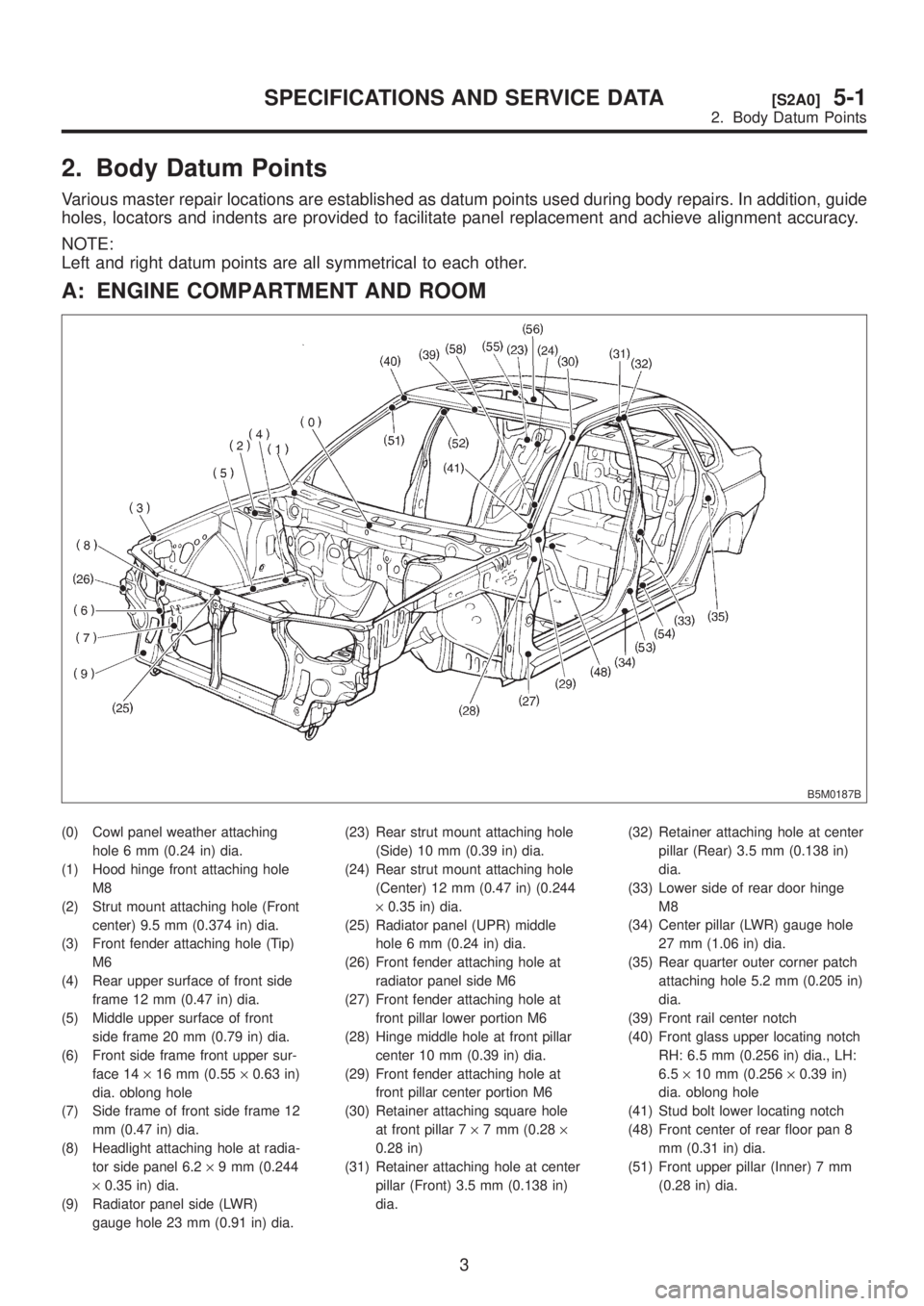
2. Body Datum Points
Various master repair locations are established as datum points used during body repairs. In addition, guide
holes, locators and indents are provided to facilitate panel replacement and achieve alignment accuracy.
NOTE:
Left and right datum points are all symmetrical to each other.
A: ENGINE COMPARTMENT AND ROOM
B5M0187B
(0) Cowl panel weather attaching
hole 6 mm (0.24 in) dia.
(1) Hood hinge front attaching hole
M8
(2) Strut mount attaching hole (Front
center) 9.5 mm (0.374 in) dia.
(3) Front fender attaching hole (Tip)
M6
(4) Rear upper surface of front side
frame 12 mm (0.47 in) dia.
(5) Middle upper surface of front
side frame 20 mm (0.79 in) dia.
(6) Front side frame front upper sur-
face 14´16 mm (0.55´0.63 in)
dia. oblong hole
(7) Side frame of front side frame 12
mm (0.47 in) dia.
(8) Headlight attaching hole at radia-
tor side panel 6.2´9 mm (0.244
´0.35 in) dia.
(9) Radiator panel side (LWR)
gauge hole 23 mm (0.91 in) dia.(23) Rear strut mount attaching hole
(Side) 10 mm (0.39 in) dia.
(24) Rear strut mount attaching hole
(Center) 12 mm (0.47 in) (0.244
´0.35 in) dia.
(25) Radiator panel (UPR) middle
hole 6 mm (0.24 in) dia.
(26) Front fender attaching hole at
radiator panel side M6
(27) Front fender attaching hole at
front pillar lower portion M6
(28) Hinge middle hole at front pillar
center 10 mm (0.39 in) dia.
(29) Front fender attaching hole at
front pillar center portion M6
(30) Retainer attaching square hole
at front pillar 7´7 mm (0.28´
0.28 in)
(31) Retainer attaching hole at center
pillar (Front) 3.5 mm (0.138 in)
dia.(32) Retainer attaching hole at center
pillar (Rear) 3.5 mm (0.138 in)
dia.
(33) Lower side of rear door hinge
M8
(34) Center pillar (LWR) gauge hole
27 mm (1.06 in) dia.
(35) Rear quarter outer corner patch
attaching hole 5.2 mm (0.205 in)
dia.
(39) Front rail center notch
(40) Front glass upper locating notch
RH: 6.5 mm (0.256 in) dia., LH:
6.5´10 mm (0.256´0.39 in)
dia. oblong hole
(41) Stud bolt lower locating notch
(48) Front center of rear floor pan 8
mm (0.31 in) dia.
(51) Front upper pillar (Inner) 7 mm
(0.28 in) dia.
3
[S2A0]5-1SPECIFICATIONS AND SERVICE DATA
2. Body Datum Points
Page 1060 of 1456
1. Hood
A: REMOVAL AND INSTALLATION
NOTE:
The hood lock has a dual locking design which
consists of a main lock and a safety lock mecha-
nism. When the release knob located at the front
pillar on the driver's side is pulled back, the main
lock is released through the cable attached to the
knob.
The safety lock can be released by pushing the
lever protruding above the front grill while opening
the hood.
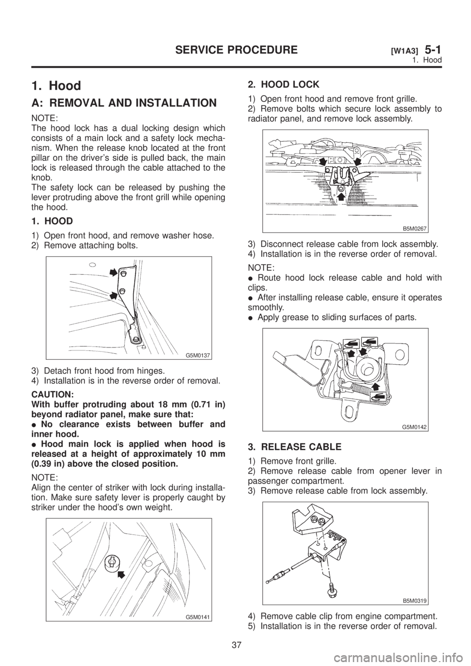
1. HOOD
1) Open front hood, and remove washer hose.
2) Remove attaching bolts.
G5M0137
3) Detach front hood from hinges.
4) Installation is in the reverse order of removal.
CAUTION:
With buffer protruding about 18 mm (0.71 in)
beyond radiator panel, make sure that:
INo clearance exists between buffer and
inner hood.
IHood main lock is applied when hood is
released at a height of approximately 10 mm
(0.39 in) above the closed position.
NOTE:
Align the center of striker with lock during installa-
tion. Make sure safety lever is properly caught by
striker under the hood's own weight.
G5M0141
2. HOOD LOCK
1) Open front hood and remove front grille.
2) Remove bolts which secure lock assembly to
radiator panel, and remove lock assembly.
B5M0267
3) Disconnect release cable from lock assembly.
4) Installation is in the reverse order of removal.
NOTE:
IRoute hood lock release cable and hold with
clips.
IAfter installing release cable, ensure it operates
smoothly.
IApply grease to sliding surfaces of parts.
G5M0142
3. RELEASE CABLE
1) Remove front grille.
2) Remove release cable from opener lever in
passenger compartment.
3) Remove release cable from lock assembly.
B5M0319
4) Remove cable clip from engine compartment.
5) Installation is in the reverse order of removal.
37
[W1A3]5-1SERVICE PROCEDURE
1. Hood
Page 1066 of 1456
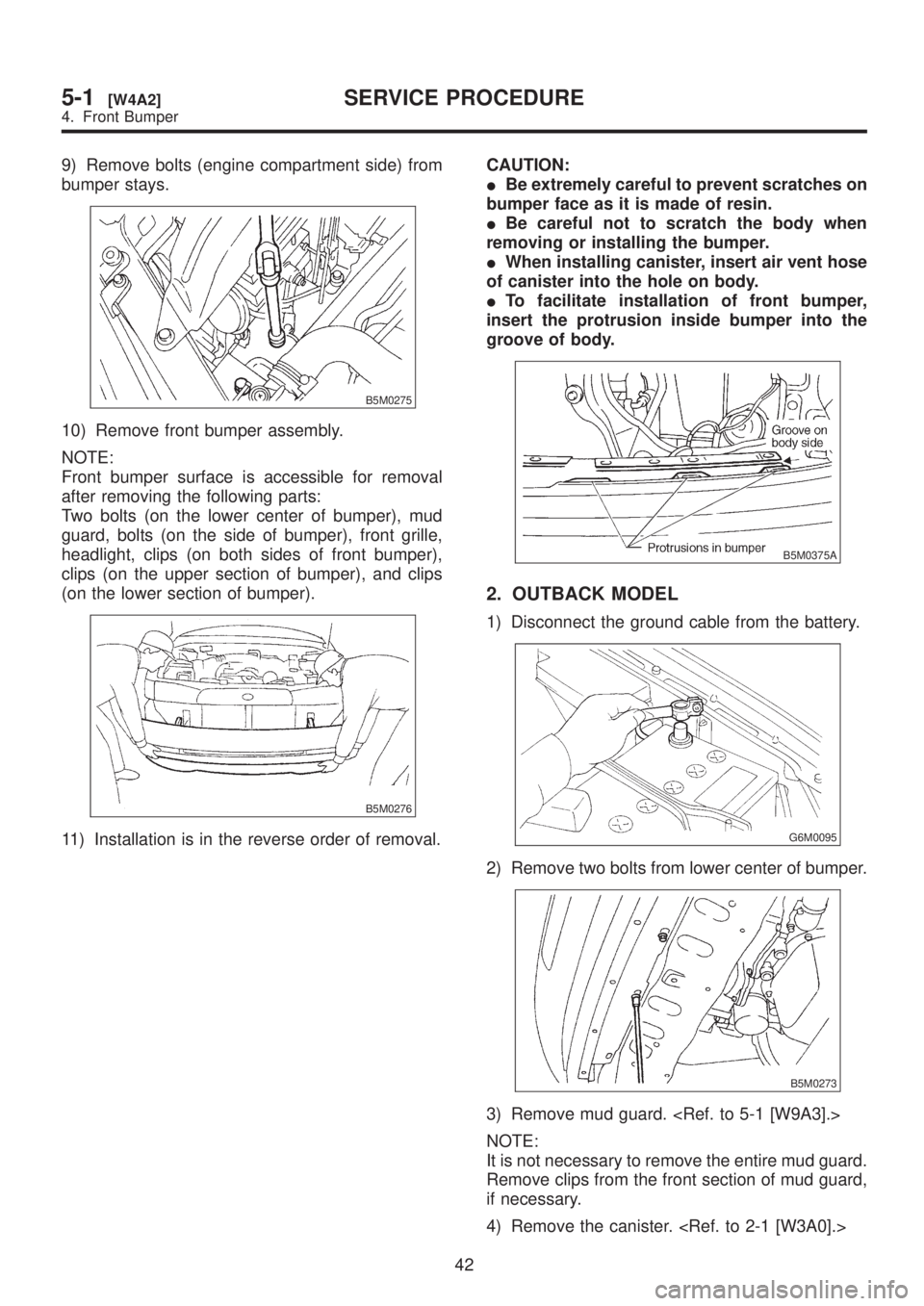
9) Remove bolts (engine compartment side) from
bumper stays.
B5M0275
10) Remove front bumper assembly.
NOTE:
Front bumper surface is accessible for removal
after removing the following parts:
Two bolts (on the lower center of bumper), mud
guard, bolts (on the side of bumper), front grille,
headlight, clips (on both sides of front bumper),
clips (on the upper section of bumper), and clips
(on the lower section of bumper).
B5M0276
11) Installation is in the reverse order of removal.CAUTION:
IBe extremely careful to prevent scratches on
bumper face as it is made of resin.
IBe careful not to scratch the body when
removing or installing the bumper.
IWhen installing canister, insert air vent hose
of canister into the hole on body.
ITo facilitate installation of front bumper,
insert the protrusion inside bumper into the
groove of body.
B5M0375A
2. OUTBACK MODEL
1) Disconnect the ground cable from the battery.
G6M0095
2) Remove two bolts from lower center of bumper.
B5M0273
3) Remove mud guard.
NOTE:
It is not necessary to remove the entire mud guard.
Remove clips from the front section of mud guard,
if necessary.
4) Remove the canister.
42
5-1[W4A2]SERVICE PROCEDURE
4. Front Bumper