Page 1067 of 1456
![SUBARU LEGACY 1999 Service Repair Manual 5) Remove two bolts from side of bumper.
B5M0274
6) Remove front grill. <Ref. to 5-1 [W12A0].>
7) Remove headlight. <Ref. to 6-2 [W4B2].>
8) Remove fog lamps.
9) Remove clips from both sides of front SUBARU LEGACY 1999 Service Repair Manual 5) Remove two bolts from side of bumper.
B5M0274
6) Remove front grill. <Ref. to 5-1 [W12A0].>
7) Remove headlight. <Ref. to 6-2 [W4B2].>
8) Remove fog lamps.
9) Remove clips from both sides of front](/manual-img/17/57435/w960_57435-1066.png)
5) Remove two bolts from side of bumper.
B5M0274
6) Remove front grill.
7) Remove headlight.
8) Remove fog lamps.
9) Remove clips from both sides of front bumper.
NOTE:
When removing, push the pin at the center of clip
with a thin screwdriver.
B5M0376
10) Remove bolts (engine compartment side) from
bumper stays.
B5M0275
11) Remove front bumper assembly.
NOTE:
Front bumper surface is accessible for removal
after removing the following parts:
Two bolts (on the lower center of bumper), mud
guard, bolts (on the side of bumper), front grille,
headlight, clips (on both sides of front bumper),
clips (on the upper section of bumper), and clips
(on the lower section of bumper).
B5M0406
12) Installation is in the reverse order of removal.
CAUTION:
IBe extremely careful to prevent scratches on
bumper face as it is made of resin.
IBe careful not to scratch the body when
removing or installing the bumper.
IWhen installing canister, insert air vent hose
of canister into the hole on body.
ITo facilitate installation of front bumper,
insert the protrusion inside bumper into the
groove of body.
B5M0375A
43
[W4A2]5-1SERVICE PROCEDURE
4. Front Bumper
Page 1183 of 1456
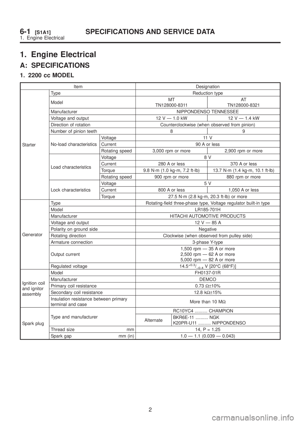
1. Engine Electrical
A: SPECIFICATIONS
1. 2200 cc MODEL
Item Designation
StarterType Reduction type
ModelMT
TN128000-8311AT
TN128000-8321
Manufacturer NIPPONDENSO TENNESSEE
Voltage and output 12 V Ð 1.0 kW 12 V Ð 1.4 kW
Direction of rotation Counterclockwise (when observed from pinion)
Number of pinion teeth 8 9
No-load characteristicsVoltage 11 V
Current 90 A or less
Rotating speed 3,000 rpm or more 2,900 rpm or more
Load characteristicsVoltage 8 V
Current 280 A or less 370 A or less
Torque 9.8 N´m (1.0 kg-m, 7.2 ft-lb) 13.7 N´m (1.4 kg-m, 10.1 ft-lb)
Rotating speed 900 rpm or more 880 rpm or more
Lock characteristicsVoltage 5 V
Current 800 A or less 1,050 A or less
Torque 27.5 N´m (2.8 kg-m, 20.3 ft-lb) or more
GeneratorType Rotating-field three-phase type, Voltage regulator built-in type
Model LR185-701H
Manufacturer HITACHI AUTOMOTIVE PRODUCTS
Voltage and output 12VÐ85A
Polarity on ground side Negative
Rotating direction Clockwise (when observed from pulley side)
Armature connection 3-phase Y-type
Output current1,500 rpm Ð 35 A or more
2,500 rpm Ð 62 A or more
5,000 rpm Ð 82 A or more
Regulated voltage 14.5
+0.3/þ0.4V [20ÉC (68ÉF)]
Ignition coil
and ignitor
assemblyModel FH0137-01R
Manufacturer DEMCO
Primary coil resistance 0.73W±10%
Secondary coil resistance 12.8 kW±15%
Insulation resistance between primary
terminal and caseMore than 10 MW
Spark plugType and manufacturerRC10YC4 .......... CHAMPION
AlternateBKR6E-11 .......... NGK
K20PR-U11 .......... NIPPONDENSO
Thread size mm 14, P = 1.25
Spark gap mm (in) 1.0 Ð 1.1 (0.039 Ð 0.043)
2
6-1[S1A1]SPECIFICATIONS AND SERVICE DATA
1. Engine Electrical
Page 1184 of 1456
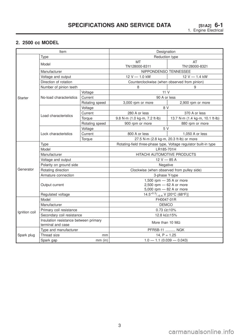
2. 2500 cc MODEL
Item Designation
StarterType Reduction type
ModelMT
TN128000-8311AT
TN128000-8321
Manufacturer NIPPONDENSO TENNESSEE
Voltage and output 12 V Ð 1.0 kW 12 V Ð 1.4 kW
Direction of rotation Counterclockwise (when observed from pinion)
Number of pinion teeth 8 9
No-load characteristicsVoltage 11 V
Current 90 A or less
Rotating speed 3,000 rpm or more 2,900 rpm or more
Load characteristicsVoltage 8 V
Current 280 A or less 370 A or less
Torque 9.8 N´m (1.0 kg-m, 7.2 ft-lb) 13.7 N´m (1.4 kg-m, 10.1 ft-lb)
Rotating speed 900 rpm or more 880 rpm or more
Lock characteristicsVoltage 5 V
Current 800 A or less 1,050 A or less
Torque 27.5 N´m (2.8 kg-m, 20.3 ft-lb) or more
GeneratorType Rotating-field three-phase type, Voltage regulator built-in type
Model LR185-701H
Manufacturer HITACHI AUTOMOTIVE PRODUCTS
Voltage and output 12VÐ85A
Polarity on ground side Negative
Rotating direction Clockwise (when observed from pulley side)
Armature connection 3-phase Y-type
Output current1,500 rpm Ð 35 A or more
2,500 rpm Ð 62 A or more
5,000 rpm Ð 82 A or more
Regulated voltage 14.5
+0.3/þ0.4V [20ÉC (68ÉF)]
Ignition coilModel FH0047-01R
Manufacturer DEMCO
Primary coil resistance 0.73W±10%
Secondary coil resistance 12.8 kW±15%
Insulation resistance between primary
terminal and caseMore than 10 MW
Spark plugType and manufacturer PFR5B-11 .......... NGK
Thread size mm 14, P = 1.25
Spark gap mm (in) 1.0 Ð 1.1 (0.039 Ð 0.043)
3
[S1A2]6-1SPECIFICATIONS AND SERVICE DATA
1. Engine Electrical
Page 1201 of 1456
D: ASSEMBLY
Assembly is in the reverse order of disassembly
procedures.
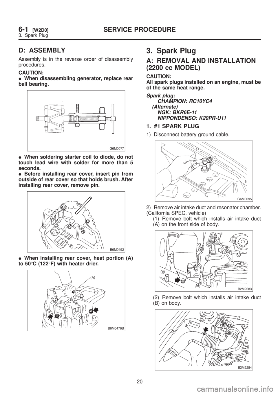
CAUTION:
IWhen disassembling generator, replace rear
ball bearing.
G6M0077
IWhen soldering starter coil to diode, do not
touch lead wire with solder for more than 5
seconds.
IBefore installing rear cover, insert pin from
outside of rear cover so that holds brush. After
installing rear cover, remove pin.
B6M0492
IWhen installing rear cover, heat portion (A)
to 50ÉC (122ÉF) with heater drier.
B6M0476B
3. Spark Plug
A: REMOVAL AND INSTALLATION
(2200 cc MODEL)
CAUTION:
All spark plugs installed on an engine, must be
of the same heat range.
Spark plug:
CHAMPION: RC10YC4
(Alternate)
NGK: BKR6E-11
NIPPONDENSO: K20PR-U11
1. #1 SPARK PLUG
1) Disconnect battery ground cable.
G6M0095
2) Remove air intake duct and resonator chamber.
(California SPEC. vehicle)
(1) Remove bolt which installs air intake duct
(A) on the front side of body.
B2M2283
(2) Remove bolt which installs air intake duct
(B) on body.
B2M2284
20
6-1[W2D0]SERVICE PROCEDURE
3. Spark Plug
Page 1202 of 1456
D: ASSEMBLY
Assembly is in the reverse order of disassembly
procedures.
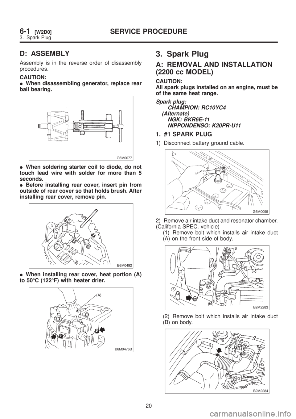
CAUTION:
IWhen disassembling generator, replace rear
ball bearing.
G6M0077
IWhen soldering starter coil to diode, do not
touch lead wire with solder for more than 5
seconds.
IBefore installing rear cover, insert pin from
outside of rear cover so that holds brush. After
installing rear cover, remove pin.
B6M0492
IWhen installing rear cover, heat portion (A)
to 50ÉC (122ÉF) with heater drier.
B6M0476B
3. Spark Plug
A: REMOVAL AND INSTALLATION
(2200 cc MODEL)
CAUTION:
All spark plugs installed on an engine, must be
of the same heat range.
Spark plug:
CHAMPION: RC10YC4
(Alternate)
NGK: BKR6E-11
NIPPONDENSO: K20PR-U11
1. #1 SPARK PLUG
1) Disconnect battery ground cable.
G6M0095
2) Remove air intake duct and resonator chamber.
(California SPEC. vehicle)
(1) Remove bolt which installs air intake duct
(A) on the front side of body.
B2M2283
(2) Remove bolt which installs air intake duct
(B) on body.
B2M2284
20
6-1[W2D0]SERVICE PROCEDURE
3. Spark Plug
Page 1207 of 1456
B: REMOVAL AND INSTALLATION
(2500 cc EXCEPT OUTBACK
MODEL)
CAUTION:
All spark plugs installed on an engine, must be
of the same heat range.
Spark plug:
NGK: PFR5B-11
1. #1 SPARK PLUG
1) Disconnect battery ground cable.
G6M0095
2) Remove #1 spark plug cord by pulling boot, not
cord itself.
B6M0552A
3) Remove spark plug with the spark plug socket.
B6M0553
4) Installation is in the reverse order of removal.
Tightening torque (Spark plug):
20.6
±2.9 N´m (2.10±0.30 kg-m, 15.19±2.14
ft-lb)
2. #2 SPARK PLUG
1) Disconnect battery ground cable.
G6M0095
2) Remove battery.
B6M0554
3) Remove #2 spark plug cord by pulling boot, not
cord itself.
B6M0555A
4) Remove spark plug with the spark plug socket.
B6M0556
5) Installation is in the reverse order of removal.
25
[W3B2]6-1SERVICE PROCEDURE
3. Spark Plug
Page 1210 of 1456
C: REMOVAL (2500 cc OUTBACK
MODEL)
CAUTION:
All spark plugs installed on an engine, must be
of the same heat range.
Spark plug:
NGK: PFR5B-11
1. #1 SPARK PLUG
1) Disconnect battery ground cable.
G6M0095
2) Disconnect mass air flow sensor connector.
B6M0557A
3) Remove four clips securing air cleaner upper
cover.
4) Loosen the clamp screw and separate air
cleaner upper cover from air intake duct.
B6M0558
5) Remove air cleaner element and air cleaner
case.
B6M0565A
6) Remove #1 spark plug cord by pulling boot, not
cord itself.
B6M0566A
7) After connecting (A) spark plug socket, (B)
extension and (C) Universal Joint to each other,
securely set them over the spark plug in cylinder
head.
B6M0567B
(A) Spark plug socket 16 mm (5/8 in)
(B) Extension
(C) Universal Joint
(D) Extension
(E) Ratchet
8) Cover ABS pipes with a rag to prevent damage.
28
6-1[W3C0]SERVICE PROCEDURE
3. Spark Plug
Page 1215 of 1456
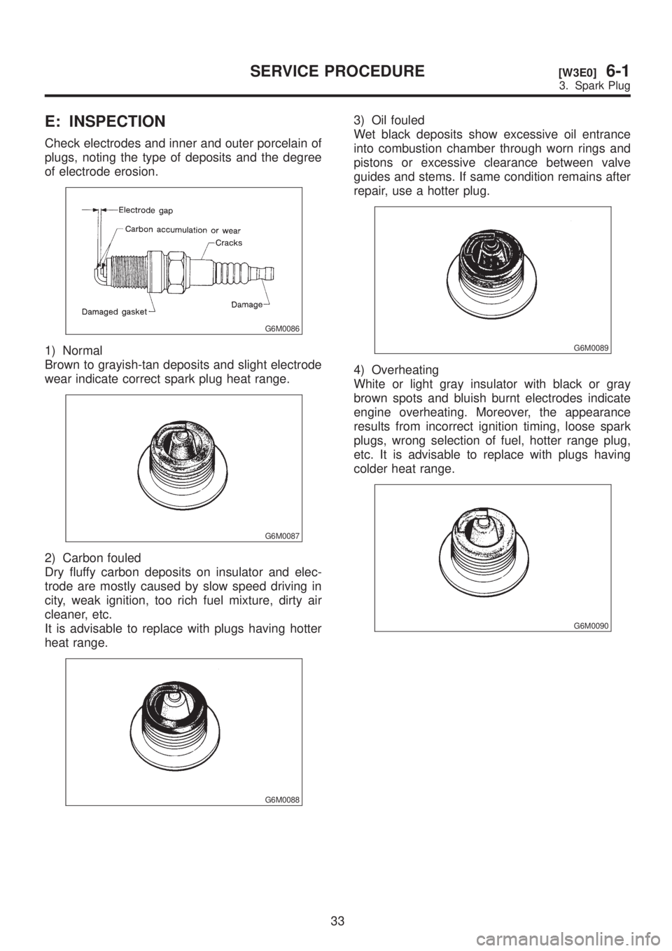
E: INSPECTION
Check electrodes and inner and outer porcelain of
plugs, noting the type of deposits and the degree
of electrode erosion.
G6M0086
1) Normal
Brown to grayish-tan deposits and slight electrode
wear indicate correct spark plug heat range.
G6M0087
2) Carbon fouled
Dry fluffy carbon deposits on insulator and elec-
trode are mostly caused by slow speed driving in
city, weak ignition, too rich fuel mixture, dirty air
cleaner, etc.
It is advisable to replace with plugs having hotter
heat range.
G6M0088
3) Oil fouled
Wet black deposits show excessive oil entrance
into combustion chamber through worn rings and
pistons or excessive clearance between valve
guides and stems. If same condition remains after
repair, use a hotter plug.
G6M0089
4) Overheating
White or light gray insulator with black or gray
brown spots and bluish burnt electrodes indicate
engine overheating. Moreover, the appearance
results from incorrect ignition timing, loose spark
plugs, wrong selection of fuel, hotter range plug,
etc. It is advisable to replace with plugs having
colder heat range.
G6M0090
33
[W3E0]6-1SERVICE PROCEDURE
3. Spark Plug