1999 SUBARU FORESTER Service Repair Manual
-
 1
1 -
 2
2 -
 3
3 -
 4
4 -
 5
5 -
 6
6 -
 7
7 -
 8
8 -
 9
9 -
 10
10 -
 11
11 -
 12
12 -
 13
13 -
 14
14 -
 15
15 -
 16
16 -
 17
17 -
 18
18 -
 19
19 -
 20
20 -
 21
21 -
 22
22 -
 23
23 -
 24
24 -
 25
25 -
 26
26 -
 27
27 -
 28
28 -
 29
29 -
 30
30 -
 31
31 -
 32
32 -
 33
33 -
 34
34 -
 35
35 -
 36
36 -
 37
37 -
 38
38 -
 39
39 -
 40
40 -
 41
41 -
 42
42 -
 43
43 -
 44
44 -
 45
45 -
 46
46 -
 47
47 -
 48
48 -
 49
49 -
 50
50 -
 51
51 -
 52
52 -
 53
53 -
 54
54 -
 55
55 -
 56
56 -
 57
57 -
 58
58 -
 59
59 -
 60
60 -
 61
61 -
 62
62 -
 63
63 -
 64
64 -
 65
65 -
 66
66 -
 67
67 -
 68
68 -
 69
69 -
 70
70 -
 71
71 -
 72
72 -
 73
73 -
 74
74 -
 75
75 -
 76
76 -
 77
77 -
 78
78 -
 79
79 -
 80
80 -
 81
81 -
 82
82 -
 83
83 -
 84
84 -
 85
85 -
 86
86 -
 87
87 -
 88
88 -
 89
89 -
 90
90 -
 91
91 -
 92
92 -
 93
93 -
 94
94 -
 95
95 -
 96
96 -
 97
97 -
 98
98 -
 99
99 -
 100
100 -
 101
101 -
 102
102 -
 103
103 -
 104
104 -
 105
105 -
 106
106 -
 107
107 -
 108
108 -
 109
109 -
 110
110 -
 111
111 -
 112
112 -
 113
113 -
 114
114 -
 115
115 -
 116
116 -
 117
117 -
 118
118 -
 119
119 -
 120
120 -
 121
121 -
 122
122 -
 123
123 -
 124
124 -
 125
125 -
 126
126 -
 127
127 -
 128
128 -
 129
129 -
 130
130 -
 131
131 -
 132
132 -
 133
133 -
 134
134 -
 135
135 -
 136
136 -
 137
137 -
 138
138 -
 139
139 -
 140
140 -
 141
141 -
 142
142 -
 143
143 -
 144
144 -
 145
145 -
 146
146 -
 147
147 -
 148
148 -
 149
149 -
 150
150 -
 151
151 -
 152
152 -
 153
153 -
 154
154 -
 155
155 -
 156
156 -
 157
157 -
 158
158 -
 159
159 -
 160
160 -
 161
161 -
 162
162 -
 163
163 -
 164
164 -
 165
165 -
 166
166 -
 167
167 -
 168
168 -
 169
169 -
 170
170 -
 171
171 -
 172
172 -
 173
173 -
 174
174 -
 175
175 -
 176
176 -
 177
177 -
 178
178 -
 179
179 -
 180
180 -
 181
181 -
 182
182 -
 183
183 -
 184
184 -
 185
185 -
 186
186 -
 187
187 -
 188
188 -
 189
189 -
 190
190 -
 191
191 -
 192
192 -
 193
193 -
 194
194 -
 195
195 -
 196
196 -
 197
197 -
 198
198 -
 199
199 -
 200
200 -
 201
201 -
 202
202 -
 203
203 -
 204
204 -
 205
205 -
 206
206 -
 207
207 -
 208
208 -
 209
209 -
 210
210 -
 211
211 -
 212
212 -
 213
213 -
 214
214 -
 215
215 -
 216
216 -
 217
217 -
 218
218 -
 219
219 -
 220
220 -
 221
221 -
 222
222 -
 223
223 -
 224
224 -
 225
225 -
 226
226 -
 227
227 -
 228
228 -
 229
229 -
 230
230 -
 231
231 -
 232
232 -
 233
233 -
 234
234 -
 235
235 -
 236
236 -
 237
237 -
 238
238 -
 239
239 -
 240
240 -
 241
241 -
 242
242 -
 243
243 -
 244
244 -
 245
245 -
 246
246 -
 247
247 -
 248
248 -
 249
249 -
 250
250 -
 251
251 -
 252
252 -
 253
253 -
 254
254 -
 255
255 -
 256
256 -
 257
257 -
 258
258 -
 259
259 -
 260
260 -
 261
261 -
 262
262 -
 263
263 -
 264
264 -
 265
265 -
 266
266 -
 267
267 -
 268
268 -
 269
269 -
 270
270 -
 271
271 -
 272
272 -
 273
273 -
 274
274 -
 275
275 -
 276
276 -
 277
277 -
 278
278 -
 279
279 -
 280
280 -
 281
281 -
 282
282 -
 283
283 -
 284
284 -
 285
285 -
 286
286 -
 287
287 -
 288
288 -
 289
289 -
 290
290 -
 291
291 -
 292
292 -
 293
293 -
 294
294 -
 295
295 -
 296
296 -
 297
297 -
 298
298 -
 299
299 -
 300
300 -
 301
301 -
 302
302 -
 303
303 -
 304
304 -
 305
305 -
 306
306 -
 307
307 -
 308
308 -
 309
309 -
 310
310 -
 311
311 -
 312
312 -
 313
313 -
 314
314 -
 315
315 -
 316
316 -
 317
317 -
 318
318 -
 319
319 -
 320
320 -
 321
321 -
 322
322 -
 323
323 -
 324
324 -
 325
325 -
 326
326 -
 327
327 -
 328
328 -
 329
329 -
 330
330 -
 331
331 -
 332
332 -
 333
333 -
 334
334 -
 335
335 -
 336
336 -
 337
337 -
 338
338 -
 339
339 -
 340
340 -
 341
341 -
 342
342 -
 343
343 -
 344
344
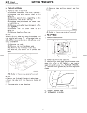
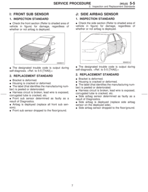
![SUBARU FORESTER 1999 Service Repair Manual 4.
A:
1\)
2\)
for
3\)
4\)
below
CAUTION:
Do
column
stalled.
G5M0312
5\)
[W1A0].>
6\)
ule.
S5M0216
7\)
airbag
\(driver
S5M0217A
8\)
from
lower
9\)
and
H5M0933B
10\)
11
[W4A0]5-5SER
4.](/manual-img/17/57427/w960_57427-280.png "SUBARU FORESTER 1999 Service Repair Manual 4.
A:
1\)
2\)
for
3\)
4\)
below
CAUTION:
Do
column
stalled.
G5M0312
5\)
[W1A0].>
6\)
ule.
S5M0216
7\)
airbag
\(driver
S5M0217A
8\)
from
lower
9\)
and
H5M0933B
10\)
11
[W4A0]5-5SER
4.")
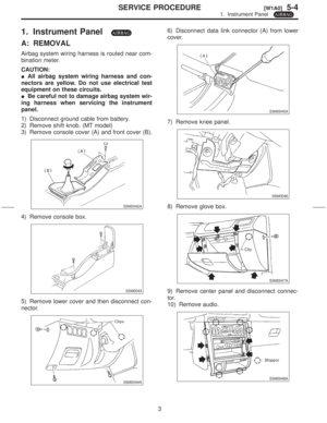
![SUBARU FORESTER 1999 Service Repair Manual 5.
A:
1\)
2\)
for
3\)
roll
4\)
5\)
from
6\)
[W7A0].>
airbag
7\)
ness.
S5M0307
8\)
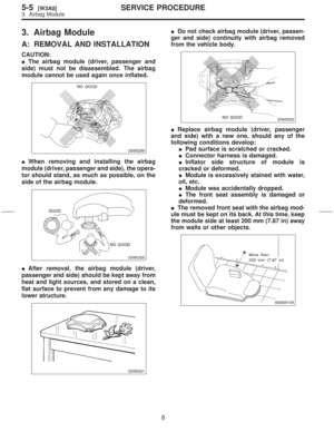
6.
A:
CAUTION:
IDo
ule.
G5M0322
I If
if
bag
G5M0323
I After
ule
light
G5M0324
1\)
2\)
for
3\)
4\)
[W1A0].>
5\)
ule.
12](/manual-img/17/57427/w960_57427-281.png "SUBARU FORESTER 1999 Service Repair Manual 5.
A:
1\)
2\)
for
3\)
roll
4\)
5\)
from
6\)
[W7A0].>
airbag
7\)
ness.
S5M0307
8\)
6.
A:
CAUTION:
IDo
ule.
G5M0322
I If
if
bag
G5M0323
I After
ule
light
G5M0324
1\)
2\)
for
3\)
4\)
[W1A0].>
5\)
ule.
12")
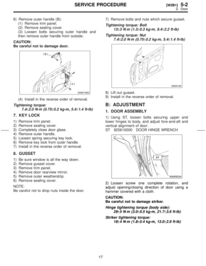
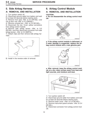
 Turn ignition switch off.
2) Disconnect ground cable from battery and wait
for at least 20 seconds before starting work.
3) Remove front seat <Ref")
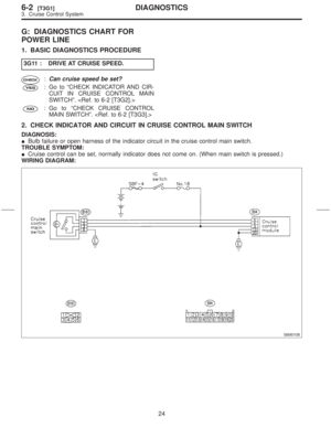
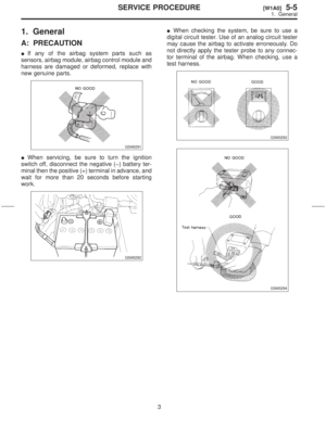
 Using T40 TORXTbit (Tamper resistant type),
remove the four TORXTbolts in numerical
sequence shown in figure. Discard the old TORXT
bolts.
CAUTION:
Use new TORXTbolts during re-assembly.
S5M0219A
7")
![SUBARU FORESTER 1999 Service Repair Manual 6\)Tbit
remove Tbolts
sequence T
bolts.
CAUTION:
Use Tbolts
S5M0219A
7\)
7.
A:
CAUTION:
I If
a
side
inflated.
deformation
replace
I When
work
the
take
ing
directly
harness
1\)
2\)
for
3\)
[W5A1].>
4\)](/manual-img/17/57427/w960_57427-284.png "SUBARU FORESTER 1999 Service Repair Manual 6\)Tbit
remove Tbolts
sequence T
bolts.
CAUTION:
Use Tbolts
S5M0219A
7\)
7.
A:
CAUTION:
I If
a
side
inflated.
deformation
replace
I When
work
the
take
ing
directly
harness
1\)
2\)
for
3\)
[W5A1].>
4\)")
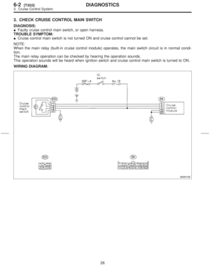
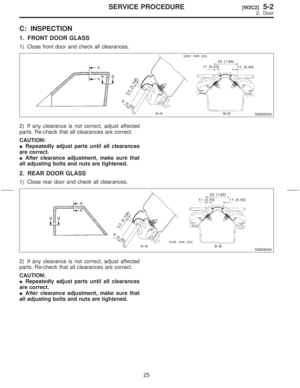
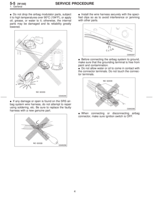
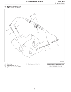
![SUBARU FORESTER 1999 Service Repair Manual 8. Roll Connector
A: REMOVAL
1) Turn ignition switch off.
2) Disconnect ground cable from battery and wait
for at least 20 seconds before starting work.
3) Remove lower cover. <Ref. to 5-4 [W1A0].>
4)](/manual-img/17/57427/w960_57427-285.png "SUBARU FORESTER 1999 Service Repair Manual 8. Roll Connector
A: REMOVAL
1) Turn ignition switch off.
2) Disconnect ground cable from battery and wait
for at least 20 seconds before starting work.
3) Remove lower cover. <Ref. to 5-4 [W1A0].>
4)")
 Disconnect connectors and then detach com-
bination switch assembly.
12) Remove lighting switch and wiper switch from
roll connector.
B5M0940
B: ADJUSTMENT
1. CENTERING ROLL CONNECTOR
Before insta")
