Page 60 of 345

3) Conduct appearance inspection on parts
selected.
NOTE:
Also check connector terminals, wiring harness,
case, etc. for damage.
:Is there anything unusual about the
appearance of airbag component
parts?
: Replace faulty airbag component parts.
: Go to step5X2.
5X2 : AIRBAG COMPONENT PARTS
VIBRATION INSPECTION
1) Gently shake check parts (to determine faults.).
2) To check airbag module or roll connector, turn
and tilt steering wheel.
CAUTION:
Do not shake or vibrate airbag control module.
:Does the component malfunction
again when shaking?
: Replace faulty airbag component parts.
: Go to step5X3.
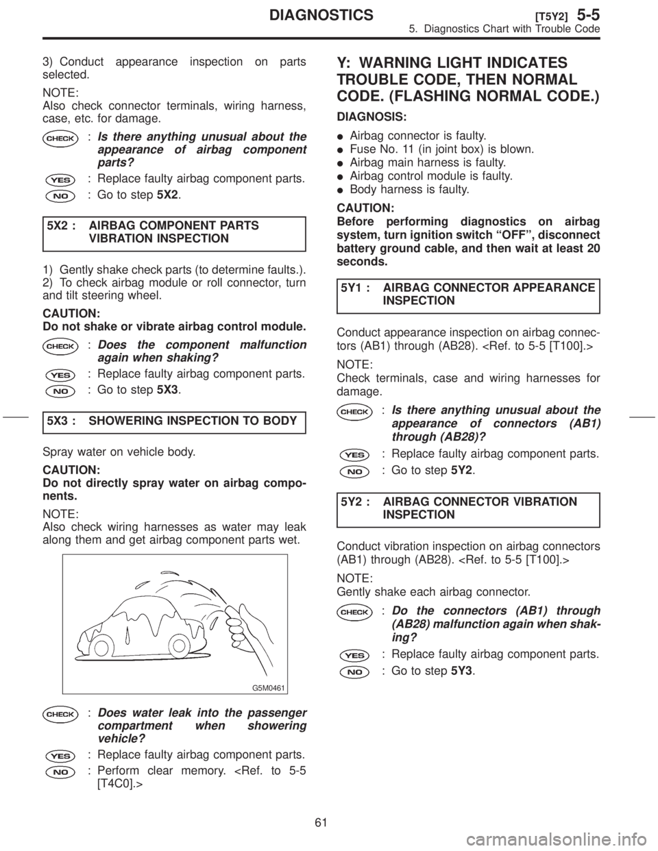
5X3 : SHOWERING INSPECTION TO BODY
Spray water on vehicle body.
CAUTION:
Do not directly spray water on airbag compo-
nents.
NOTE:
Also check wiring harnesses as water may leak
along them and get airbag component parts wet.
G5M0461
:Does water leak into the passenger
compartment when showering
vehicle?
: Replace faulty airbag component parts.
: Perform clear memory.
[T4C0].>
Y: WARNING LIGHT INDICATES
TROUBLE CODE, THEN NORMAL
CODE. (FLASHING NORMAL CODE.)
DIAGNOSIS:
IAirbag connector is faulty.
IFuse No. 11 (in joint box) is blown.
IAirbag main harness is faulty.
IAirbag control module is faulty.
IBody harness is faulty.
CAUTION:
Before performing diagnostics on airbag
system, turn ignition switch ªOFFº, disconnect
battery ground cable, and then wait at least 20
seconds.
5Y1 : AIRBAG CONNECTOR APPEARANCE
INSPECTION
Conduct appearance inspection on airbag connec-
tors (AB1) through (AB28).
NOTE:
Check terminals, case and wiring harnesses for
damage.
:Is there anything unusual about the
appearance of connectors (AB1)
through (AB28)?
: Replace faulty airbag component parts.
: Go to step5Y2.
5Y2 : AIRBAG CONNECTOR VIBRATION
INSPECTION
Conduct vibration inspection on airbag connectors
(AB1) through (AB28).
NOTE:
Gently shake each airbag connector.
:Do the connectors (AB1) through
(AB28) malfunction again when shak-
ing?
: Replace faulty airbag component parts.
: Go to step5Y3.
61
[T5Y2]5-5DIAGNOSTICS
5. Diagnostics Chart with Trouble Code
Page 276 of 345

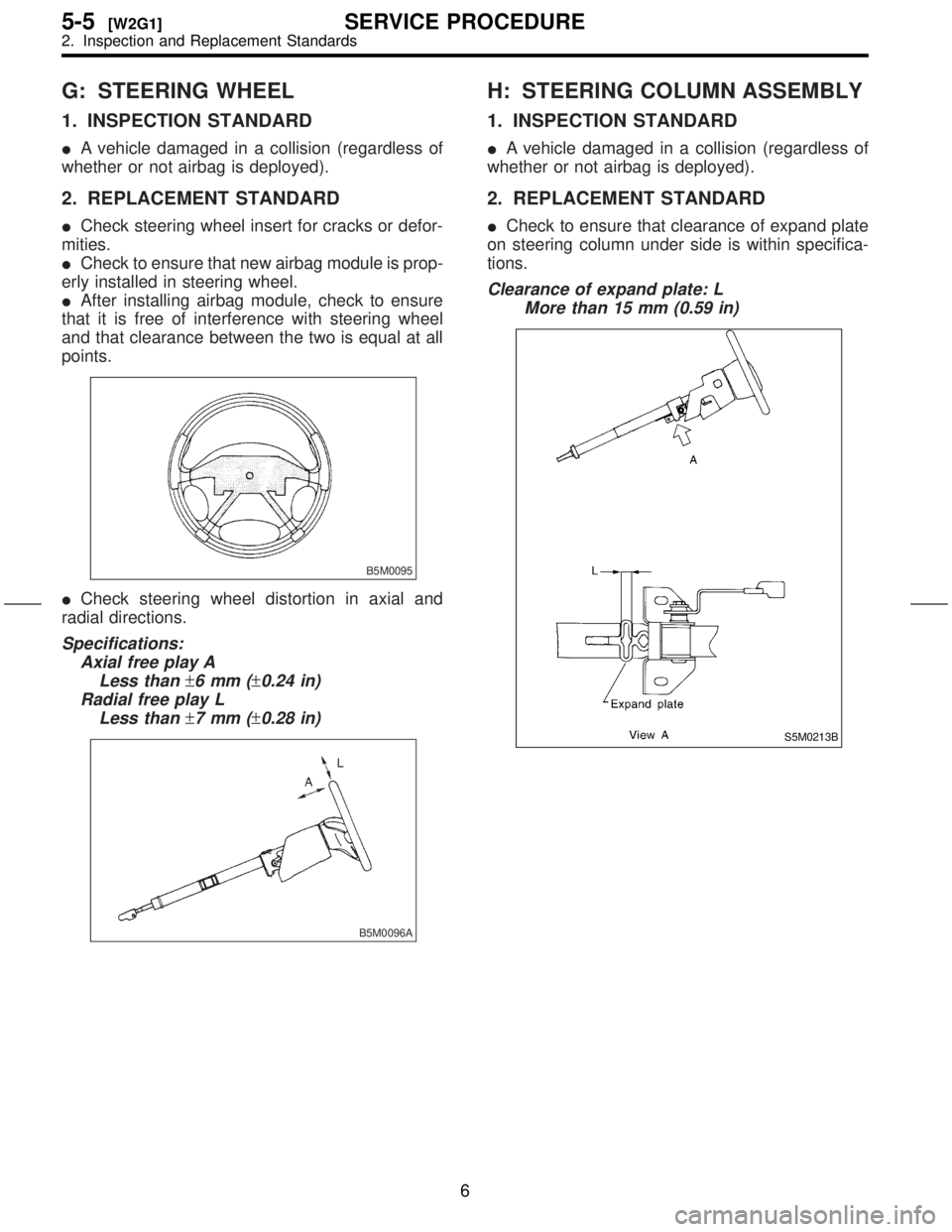
G: STEERING WHEEL
1. INSPECTION STANDARD
IA vehicle damaged in a collision (regardless of
whether or not airbag is deployed).
2. REPLACEMENT STANDARD
ICheck steering wheel insert for cracks or defor-
mities.
ICheck to ensure that new airbag module is prop-
erly installed in steering wheel.
IAfter installing airbag module, check to ensure
that it is free of interference with steering wheel
and that clearance between the two is equal at all
points.
B5M0095
ICheck steering wheel distortion in axial and
radial directions.
Specifications:
Axial free play A
Less than
±6mm(±0.24 in)
Radial free play L
Less than
±7mm(±0.28 in)
B5M0096A
H: STEERING COLUMN ASSEMBLY
1. INSPECTION STANDARD
IA vehicle damaged in a collision (regardless of
whether or not airbag is deployed).
2. REPLACEMENT STANDARD
ICheck to ensure that clearance of expand plate
on steering column under side is within specifica-
tions.
Clearance of expand plate: L
More than 15 mm (0.59 in)
S5M0213B
6
5-5[W2G1]SERVICE PROCEDURE
2. Inspection and Replacement Standards
Page 286 of 345
8. Roll Connector
A: REMOVAL
1) Turn ignition switch off.
2) Disconnect ground cable from battery and wait
for at least 20 seconds before starting work.
3) Remove lower cover.
4) Disconnect airbag connector (AB3) and (AB8)
below steering column.
CAUTION:
Do not reconnect airbag connector at steering
column until combination switch is securely re-
installed.
G5M0312
5) Disconnect combination switch connectors
from body harness connector.
6) Set front wheels in straight ahead position.
Using T30 TORXTbit, remove the two TORXT
bolts.
H5M0662
7) Disconnect airbag connector on back of airbag
module. Remove airbag
module, and place it with pad side facing upward.
H5M0664
8) Using steering puller (A), remove steering
wheel.
CAUTION:
Do not allow connector to interfere when
removing steering wheel.
S5M0436A
9) Remove steering column covers.
10) Removing the three retaining screws, remove
combination switch.
S5M0220
14
5-5[W8A0]SERVICE PROCEDURE
8. Roll Connector
Page 287 of 345

11) Disconnect connectors and then detach com-
bination switch assembly.
12) Remove lighting switch and wiper switch from
roll connector.
B5M0940
B: ADJUSTMENT
1. CENTERING ROLL CONNECTOR
Before installing steering wheel, make sure to cen-
ter roll connector built into combination switch.
1) Make sure that front wheels are positioned
straight ahead.
2) Install steering gearbox, steering shaft and
combination switch properly. Turn roll connector
pin (A) clockwise until it stops.
3) Then, back off roll connector pin (A) approxi-
mately 2.5 turns until ªGº marks aligned.
H5M0663B
C: INSTALLATION
CAUTION:
Failure to do this might damage roll connector.
1) Install lighting switch and wiper switch to roll
connector.
2) Before installing combination switch, check to
ensure that combination switch is off and front
wheels are set in the straight ahead position.
3) Install combination switch assembly and then
connect connectors.
4) Install column cover and centering roll connec-
tor.
5) Install steering wheel in neutral position. Care-
fully insert roll connector pin (A) into hole on steer-
ing wheel.
NOTE:
If steering wheel angle requires fine adjustment,
adjust tie-rod.
H5M0663B
6) Install airbag module and lower cover in the
reverse order of removal.
15
[W8C0]5-5SERVICE PROCEDURE
8. Roll Connector
Page 341 of 345

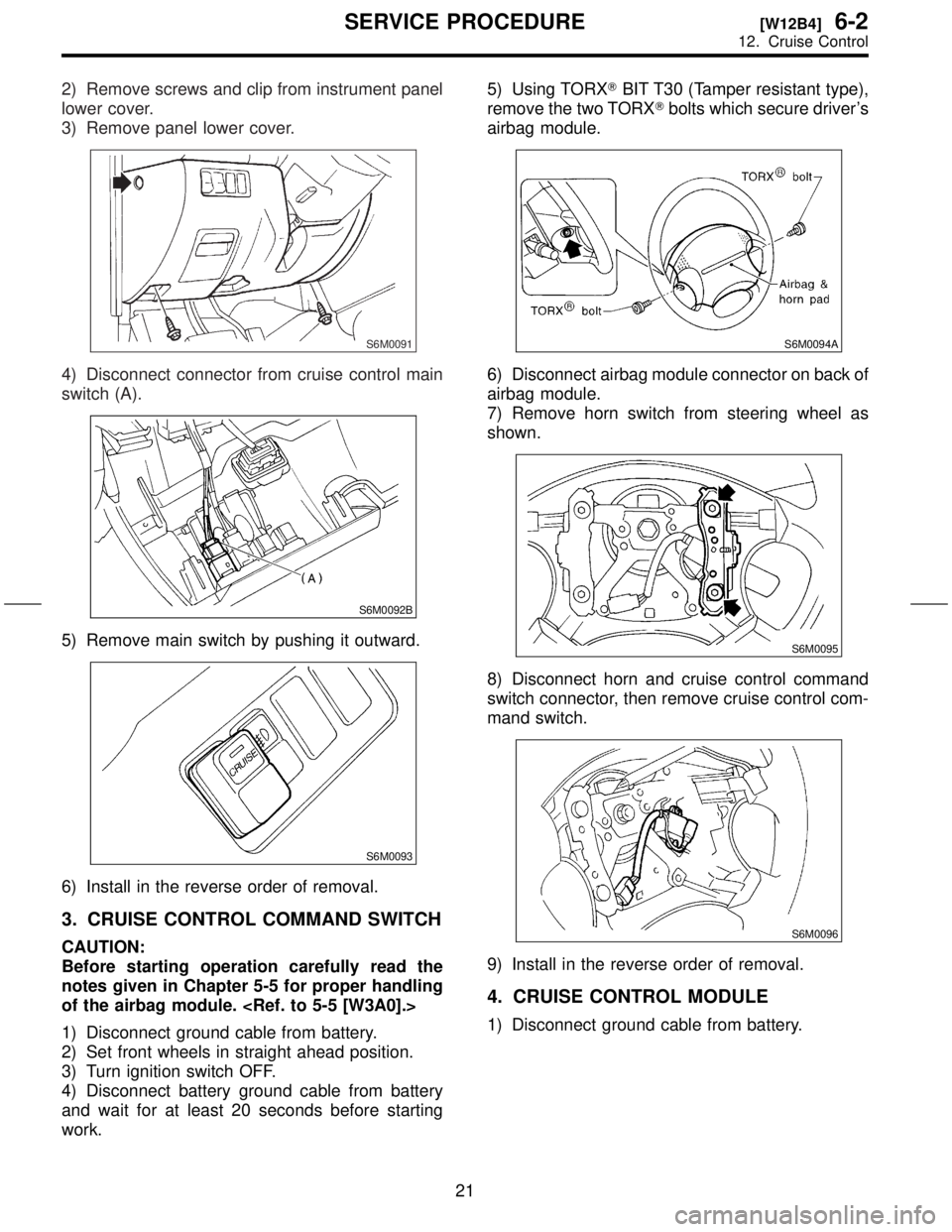
2) Remove screws and clip from instrument panel
lower cover.
3) Remove panel lower cover.
S6M0091
4) Disconnect connector from cruise control main
switch (A).
S6M0092B
5) Remove main switch by pushing it outward.
S6M0093
6) Install in the reverse order of removal.
3. CRUISE CONTROL COMMAND SWITCH
CAUTION:
Before starting operation carefully read the
notes given in Chapter 5-5 for proper handling
of the airbag module.
1) Disconnect ground cable from battery.
2) Set front wheels in straight ahead position.
3) Turn ignition switch OFF.
4) Disconnect battery ground cable from battery
and wait for at least 20 seconds before starting
work.5) Using TORXTBIT T30 (Tamper resistant type),
remove the two TORXTbolts which secure driver's
airbag module.
S6M0094A
6) Disconnect airbag module connector on back of
airbag module.
7) Remove horn switch from steering wheel as
shown.
S6M0095
8) Disconnect horn and cruise control command
switch connector, then remove cruise control com-
mand switch.
S6M0096
9) Install in the reverse order of removal.
4. CRUISE CONTROL MODULE
1) Disconnect ground cable from battery.
21
[W12B4]6-2SERVICE PROCEDURE
12. Cruise Control