1999 SUBARU FORESTER window
[x] Cancel search: windowPage 137 of 345
![SUBARU FORESTER 1999 Service Repair Manual F: DIAGNOSTICS PROCEDURE
1. BASIC DIAGNOSTICS PROCEDURE
5F11 : CHECK SECURITY SYSTEM FUNC-
TION.
1) Perform basic diagnostics procedure of keyless
entry system. <Ref. to 6-2 [T4F1].>
2) Perform pre-in SUBARU FORESTER 1999 Service Repair Manual F: DIAGNOSTICS PROCEDURE
1. BASIC DIAGNOSTICS PROCEDURE
5F11 : CHECK SECURITY SYSTEM FUNC-
TION.
1) Perform basic diagnostics procedure of keyless
entry system. <Ref. to 6-2 [T4F1].>
2) Perform pre-in](/manual-img/17/57427/w960_57427-136.png)
F: DIAGNOSTICS PROCEDURE
1. BASIC DIAGNOSTICS PROCEDURE
5F11 : CHECK SECURITY SYSTEM FUNC-
TION.
1) Perform basic diagnostics procedure of keyless
entry system.
2) Perform pre-inspection.
3) Open all windows.
4) Remove ignition key from ignition switch.
5) Set the room light switch in the middle position.
6) Close all doors and the rear gate.
7) Press the LOCK/ARM button one time.
:Does the clearance light blink one
time?
: Go to step5F12.
: Go to step5F21.
5F12 : CHECK SECURITY SYSTEM FUNC-
TION.
Check if the security indicator light blinks.
:Does the security indicator light blink
every 2 seconds?
: Go to step5F13.
: Go to step5F31.
5F13 : CHECK SECURITY SYSTEM FUNC-
TION.
Press the UNLOCK/DISARM button one time.
:Does the clearance light blink two
times?
: Go to step5F14.
: Replace security control module.
5F14 : CHECK SECURITY SYSTEM FUNC-
TION.
Check if the room light activates.
:Does the room light turn on for 30
seconds and then turn off?
: Go to step5F15.
: Replace security control module.
TION.
1) Unlock all doors with door locking switch in the
front door.
2) Open the front left door.
:Does the security indicator light blink
every 1/8 seconds?
: Go to step5F16.
: Go to step5F41.
5F16 : CHECK SECURITY SYSTEM FUNC-
TION.
Check if the clearance light activates.
:Does the clearance light blinking
remain?
: Go to step5F17.
: Replace security control module.
5F17 : CHECK SECURITY SYSTEM FUNC-
TION.
Check if the horn activates.
:Does the horn sound remain?
: Go to step5F18.
: Replace security control module.
5F18 : CHECK SECURITY SYSTEM FUNC-
TION.
Turn on starter.
:Does the starter motor activate?
: Go to step5F51.
: Go to step5F19.
5F19 : CHECK SECURITY SYSTEM FUNC-
TION.
Close the front left door.
:Does the horn sound and clearance
light blinking deactivate, and starter
motor activate after approximately 30
seconds?
: Go to step5F110.
: Replace security control module.
75
[T5F1]6-2DIAGNOSTICS
5. Security System
Page 138 of 345
5F110 : CHECK SECURITY SYSTEM FUNC-
TION.
Check if the security indicator light activates.
:Does the security indicator light blink
every 2 seconds?
: Go to step5 F 111.
: Replace security control module.
5F111 : CHECK SECURITY SYSTEM FUNC-
TION.
Open the front right door.
:Does the security indicator light blink
every 1/8 seconds, the horn sound,
the clearance light blink, and the
starter motor deactivate?
: Go to step5F112.
: Go to step5F61.
5F112 : CHECK SECURITY SYSTEM FUNC-
TION.
Press the UNLOCK/DISARM button.
:Does the security indicator light
blink, the horn and clearance light
deactivate, and the starter motor acti-
vate?
: Go to step5F113.
: Replace security control module.
5F113 : CHECK SECURITY SYSTEM FUNC-
TION.
1) Close the front right door.
2) Press the LOCK/ARM button.
3) Open the rear left door.
:Does the security indicator light blink
every 1/8 seconds, the horn sound,
the clearance light blink, and the
starter motor deactivate?
: Go to step5F114.
: Go to step5F71.5F114 : CHECK SECURITY SYSTEM FUNC-
TION.
1) Close the rear left door.
2) Open the rear right door.
:Does the security indicator light blink
every 1/8 seconds, the horn sound,
the clearance light blink, and the
starter motor deactivate?
: Go to step5F115.
: Go to step5F81.
5F115 : CHECK SECURITY SYSTEM FUNC-
TION.
1) Close the rear right door.
2) Open the rear gate.
:Does the security indicator light blink
every 1/8 seconds, the horn sound,
the clearance light blink, and the
starter motor deactivate?
: Go to step5F116.
: Go to step5F91.
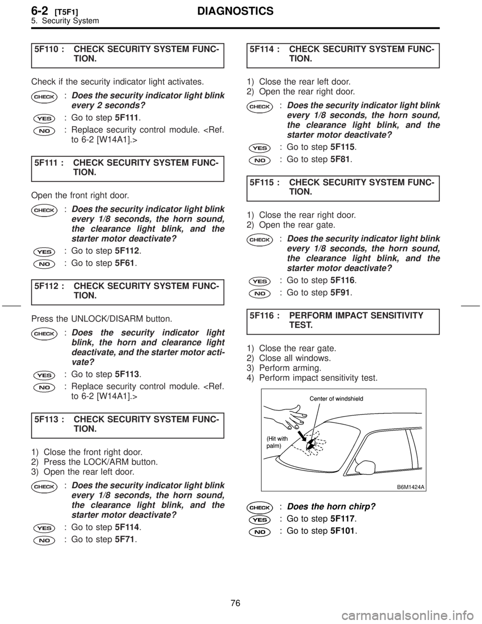
5F116 : PERFORM IMPACT SENSITIVITY
TEST.
1) Close the rear gate.
2) Close all windows.
3) Perform arming.
4) Perform impact sensitivity test.
B6M1424A
:Does the horn chirp?
: Go to step5F117.
: Go to step5F101.
76
6-2[T5F1]DIAGNOSTICS
5. Security System
Page 223 of 345
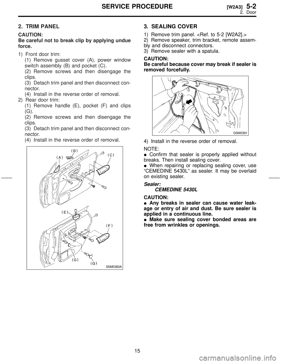
2. TRIM PANEL
CAUTION:
Be careful not to break clip by applying undue
force.
1) Front door trim:
(1) Remove gusset cover (A), power window
switch assembly (B) and pocket (C).
(2) Remove screws and then disengage the
clips.
(3) Detach trim panel and then disconnect con-
nector.
(4) Install in the reverse order of removal.
2) Rear door trim:
(1) Remove handle (E), pocket (F) and clips
(G).
(2) Remove screws and then disengage the
clips.
(3) Detach trim panel and then disconnect con-
nector.
(4) Install in the reverse order of removal.
S5M0383A
3. SEALING COVER
1) Remove trim panel.
2) Remove speaker, trim bracket, remote assem-
bly and disconnect connectors.
3) Remove sealer with a spatula.
CAUTION:
Be careful because cover may break if sealer is
removed forcefully.
G5M0391
4) Install in the reverse order of removal.
NOTE:
IConfirm that sealer is properly applied without
breaks. Then install sealing cover.
IWhen repairing or replacing sealing cover, use
ªCEMEDINE 5430Lº as sealer. It may be overlaid
on existing sealer.
Sealer:
CEMEDINE 5430L
CAUTION:
IAny breaks in sealer can cause water leak-
age or entry of air and dust. Be sure sealer is
applied in a continuous line.
IMake sure sealing cover bonded areas are
free from wrinkles or openings.
15
[W2A3]5-2SERVICE PROCEDURE
2. Door
Page 225 of 345
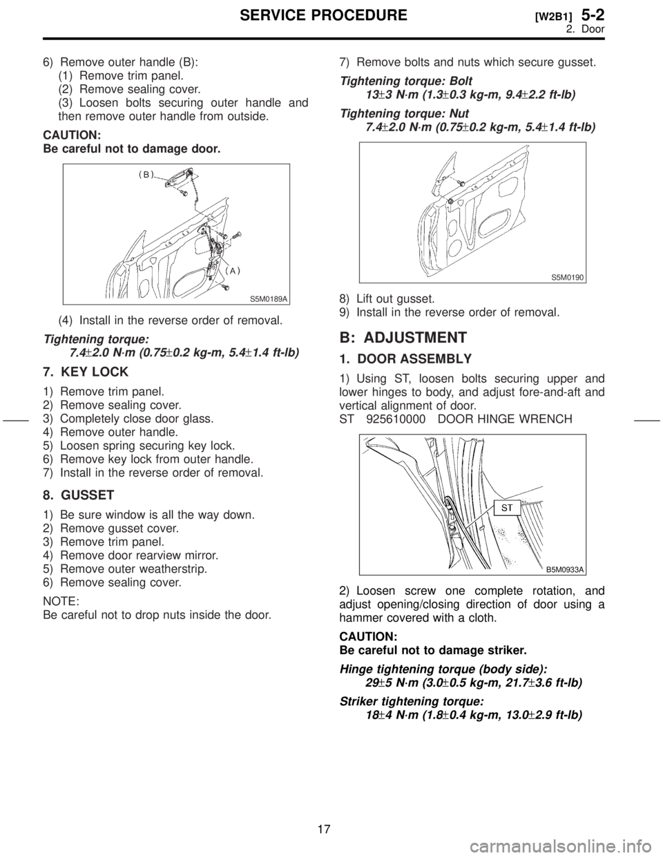
6) Remove outer handle (B):
(1) Remove trim panel.
(2) Remove sealing cover.
(3) Loosen bolts securing outer handle and
then remove outer handle from outside.
CAUTION:
Be careful not to damage door.
S5M0189A
(4) Install in the reverse order of removal.
Tightening torque:
7.4
±2.0 N´m (0.75±0.2 kg-m, 5.4±1.4 ft-lb)
7. KEY LOCK
1) Remove trim panel.
2) Remove sealing cover.
3) Completely close door glass.
4) Remove outer handle.
5) Loosen spring securing key lock.
6) Remove key lock from outer handle.
7) Install in the reverse order of removal.
8. GUSSET
1) Be sure window is all the way down.
2) Remove gusset cover.
3) Remove trim panel.
4) Remove door rearview mirror.
5) Remove outer weatherstrip.
6) Remove sealing cover.
NOTE:
Be careful not to drop nuts inside the door.7) Remove bolts and nuts which secure gusset.
Tightening torque: Bolt
13
±3 N´m (1.3±0.3 kg-m, 9.4±2.2 ft-lb)
Tightening torque: Nut
7.4
±2.0 N´m (0.75±0.2 kg-m, 5.4±1.4 ft-lb)
S5M0190
8) Lift out gusset.
9) Install in the reverse order of removal.
B: ADJUSTMENT
1. DOOR ASSEMBLY
1) Using ST, loosen bolts securing upper and
lower hinges to body, and adjust fore-and-aft and
vertical alignment of door.
ST 925610000 DOOR HINGE WRENCH
B5M0933A
2) Loosen screw one complete rotation, and
adjust opening/closing direction of door using a
hammer covered with a cloth.
CAUTION:
Be careful not to damage striker.
Hinge tightening torque (body side):
29
±5 N´m (3.0±0.5 kg-m, 21.7±3.6 ft-lb)
Striker tightening torque:
18
±4 N´m (1.8±0.4 kg-m, 13.0±2.9 ft-lb)
17
[W2B1]5-2SERVICE PROCEDURE
2. Door
Page 229 of 345
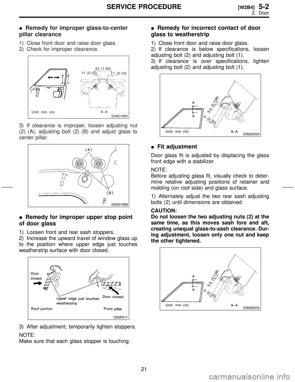
IRemedy for improper glass-to-center
pillar clearance
1) Close front door and raise door glass.
2) Check for improper clearance.
S5M0198A
3) If clearance is improper, loosen adjusting nut
(2) (A), adjusting bolt (2) (B) and adjust glass to
center pillar.
S5M0199B
IRemedy for improper upper stop point
of door glass
1) Loosen front and rear sash stoppers.
2) Increase the upward travel of window glass up
to the position where upper edge just touches
weatherstrip surface with door closed.
G5M0511
3) After adjustment, temporarily tighten stoppers.
NOTE:
Make sure that each glass stopper is touching.
IRemedy for incorrect contact of door
glass to weatherstrip
1) Close front door and raise door glass.
2) If clearance is below specifications, loosen
adjusting bolt (2) and adjusting bolt (1).
3) If clearance is over specifications, tighten
adjusting bolt (2) and adjusting bolt (1).
S5M0200A
IFit adjustment
Door glass fit is adjusted by displacing the glass
front edge with a stabilizer.
NOTE:
Before adjusting glass fit, visually check to deter-
mine relative adjusting positions of retainer and
molding (on roof side) and glass surface.
1) Alternately adjust the two rear sash adjusting
bolts (2) until dimensions are obtained.
CAUTION:
Do not loosen the two adjusting nuts (2) at the
same time, as this moves sash fore and aft,
creating unequal glass-to-sash clearance. Dur-
ing adjustment, loosen only one nut and keep
the other tightened.
S5M0200A
21
[W2B4]5-2SERVICE PROCEDURE
2. Door
Page 234 of 345
3. Rear Gate
A: REMOVAL AND INSTALLATION
CAUTION:
IBe careful not to scratch coated surfaces of
vehicle body and window glass during
removal. Place a cloth over the affected area.
IBe careful not to damage trim panels.
IUse an assistant when handling heavy parts.
IBe careful not to damage or lose small parts.
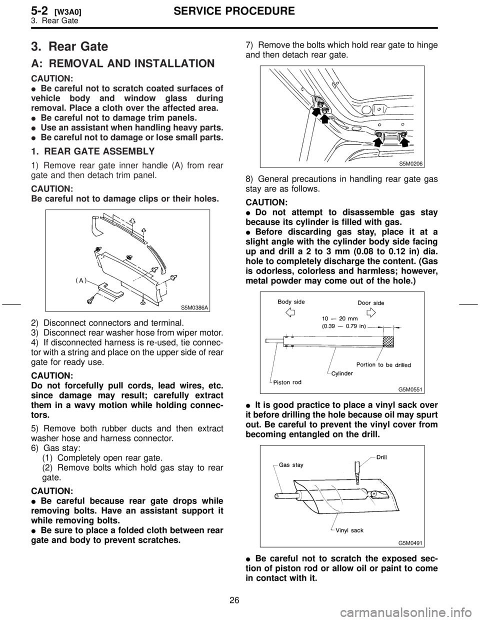
1. REAR GATE ASSEMBLY
1) Remove rear gate inner handle (A) from rear
gate and then detach trim panel.
CAUTION:
Be careful not to damage clips or their holes.
S5M0386A
2) Disconnect connectors and terminal.
3) Disconnect rear washer hose from wiper motor.
4) If disconnected harness is re-used, tie connec-
tor with a string and place on the upper side of rear
gate for ready use.
CAUTION:
Do not forcefully pull cords, lead wires, etc.
since damage may result; carefully extract
them in a wavy motion while holding connec-
tors.
5) Remove both rubber ducts and then extract
washer hose and harness connector.
6) Gas stay:
(1) Completely open rear gate.
(2) Remove bolts which hold gas stay to rear
gate.
CAUTION:
IBe careful because rear gate drops while
removing bolts. Have an assistant support it
while removing bolts.
IBe sure to place a folded cloth between rear
gate and body to prevent scratches.7) Remove the bolts which hold rear gate to hinge
and then detach rear gate.
S5M0206
8) General precautions in handling rear gate gas
stay are as follows.
CAUTION:
IDo not attempt to disassemble gas stay
because its cylinder is filled with gas.
IBefore discarding gas stay, place it at a
slight angle with the cylinder body side facing
up and drilla2to3mm(0.08 to 0.12 in) dia.
hole to completely discharge the content. (Gas
is odorless, colorless and harmless; however,
metal powder may come out of the hole.)
G5M0551
IIt is good practice to place a vinyl sack over
it before drilling the hole because oil may spurt
out. Be careful to prevent the vinyl cover from
becoming entangled on the drill.
G5M0491
IBe careful not to scratch the exposed sec-
tion of piston rod or allow oil or paint to come
in contact with it.
26
5-2[W3A0]SERVICE PROCEDURE
3. Rear Gate
Page 238 of 345
5. Windshield
A: REMOVAL
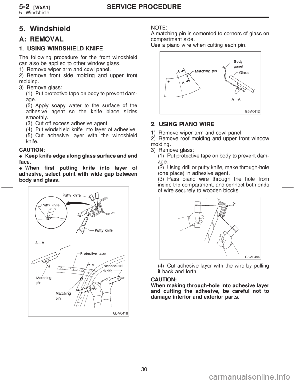
1. USING WINDSHIELD KNIFE
The following procedure for the front windshield
can also be applied to other window glass.
1) Remove wiper arm and cowl panel.
2) Remove front side molding and upper front
molding.
3) Remove glass:
(1) Put protective tape on body to prevent dam-
age.
(2) Apply soapy water to the surface of the
adhesive agent so the knife blade slides
smoothly.
(3) Cut off excess adhesive agent.
(4) Put windshield knife into layer of adhesive.
(5) Cut adhesive layer with the windshield
knife.
CAUTION:
IKeep knife edge along glass surface and end
face.
IWhen first putting knife into layer of
adhesive, select point with wide gap between
body and glass.
G5M0418
NOTE:
A matching pin is cemented to corners of glass on
compartment side.
Use a piano wire when cutting each pin.
G5M0412
2. USING PIANO WIRE
1) Remove wiper arm and cowl panel.
2) Remove roof molding and upper front window
molding.
3) Remove glass:
(1) Put protective tape on body to prevent dam-
age.
(2) Using drill or putty knife, make through-hole
(one place) in adhesive agent.
(3) Pass piano wire through the hole from
inside the compartment, and connect both ends
of wire securely to wooden blocks.
G5M0494
(4) Cut adhesive layer with the wire by pulling
it back and forth.
CAUTION:
When making through-hole into adhesive layer
and cutting the adhesive, be careful not to
damage interior and exterior parts.
30
5-2[W5A1]SERVICE PROCEDURE
5. Windshield
Page 240 of 345
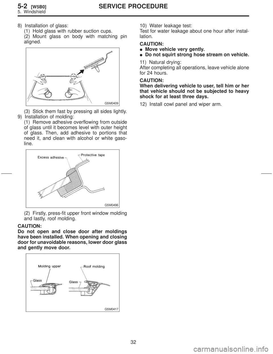
8) Installation of glass:
(1) Hold glass with rubber suction cups.
(2) Mount glass on body with matching pin
aligned.
G5M0409
(3) Stick them fast by pressing all sides lightly.
9) Installation of molding:
(1) Remove adhesive overflowing from outside
of glass until it becomes level with outer height
of glass. Then, add adhesive to portions that
need it, and clean with alcohol or white gaso-
line.
G5M0496
(2) Firstly, press-fit upper front window molding
and lastly, roof molding.
CAUTION:
Do not open and close door after moldings
have been installed. When opening and closing
door for unavoidable reasons, lower door glass
and gently move door.
G5M0417
10) Water leakage test:
Test for water leakage about one hour after instal-
lation.
CAUTION:
IMove vehicle very gently.
IDo not squirt strong hose stream on vehicle.
11) Natural drying:
After completing all operations, leave vehicle alone
for 24 hours.
CAUTION:
When delivering vehicle to user, tell him or her
that vehicle should not be subjected to heavy
shock for at least three days.
12) Install cowl panel and wiper arm.
32
5-2[W5B0]SERVICE PROCEDURE
5. Windshield