Page 305 of 345

(3) Set a new bearing and closely install a fit
tool on the bearing outer race. Press the bear-
ing down into place with a hand press or vise.
A socket wrench can serve as the tool.
(4) Install front bearing retainer.
S6M0410A
(A) Bearing
(B) Socket wrench
(C) Front bracket
D: ASSEMBLY
Assemble in the reverse order of disassembly.
1) Pulling up brush
Before assembling, press the brush down into the
brush holder with your finger and secure in that
position by passing a [2 mm (0.08 in) dia. length 4
to 5 cm (1.6 to 2.0 in)] wire (A) through the hole
shown in the figure.
CAUTION:
Be sure to remove the wire after reassembly.
S6M0411A
2) Heat the bearing box in the rear bracket [50 to
60ÉC (122 to 140ÉF)] and press the rear bearing
into the rear bracket.
CAUTION:
Grease should not be applied for the rear bear-
ing. Remove oil completely if it is found on the
bearing box.
3) After reassembly, turn the pulley by hand to
check that the rotor turns smoothly.
3. Spark Plug
A: REMOVAL AND INSTALLATION
CAUTION:
All spark plugs installed on an engine, must be
of the same heat range.
Spark plug:
CHAMPION: RC10YC4
(Alternate)
CHAMPION: RC8YC4
NGK: BKR6E-11
NIPPONDENSO: K20PR-U11
1. #1 SPARK PLUG
1) Disconnect battery ground cable.
G6M0095
2) Remove air intake duct and resonator chamber.
(1) Remove bolt which installs air intake duct
on the front side of body.
S6M0708
(2) Remove bolt which installs air intake duct
on body.
B2M2284
16
6-1[W2D0]SERVICE PROCEDURE
3. Spark Plug
Page 306 of 345

(3) Set a new bearing and closely install a fit
tool on the bearing outer race. Press the bear-
ing down into place with a hand press or vise.
A socket wrench can serve as the tool.
(4) Install front bearing retainer.
S6M0410A
(A) Bearing
(B) Socket wrench
(C) Front bracket
D: ASSEMBLY
Assemble in the reverse order of disassembly.
1) Pulling up brush
Before assembling, press the brush down into the
brush holder with your finger and secure in that
position by passing a [2 mm (0.08 in) dia. length 4
to 5 cm (1.6 to 2.0 in)] wire (A) through the hole
shown in the figure.
CAUTION:
Be sure to remove the wire after reassembly.
S6M0411A
2) Heat the bearing box in the rear bracket [50 to
60ÉC (122 to 140ÉF)] and press the rear bearing
into the rear bracket.
CAUTION:
Grease should not be applied for the rear bear-
ing. Remove oil completely if it is found on the
bearing box.
3) After reassembly, turn the pulley by hand to
check that the rotor turns smoothly.
3. Spark Plug
A: REMOVAL AND INSTALLATION
CAUTION:
All spark plugs installed on an engine, must be
of the same heat range.
Spark plug:
CHAMPION: RC10YC4
(Alternate)
CHAMPION: RC8YC4
NGK: BKR6E-11
NIPPONDENSO: K20PR-U11
1. #1 SPARK PLUG
1) Disconnect battery ground cable.
G6M0095
2) Remove air intake duct and resonator chamber.
(1) Remove bolt which installs air intake duct
on the front side of body.
S6M0708
(2) Remove bolt which installs air intake duct
on body.
B2M2284
16
6-1[W2D0]SERVICE PROCEDURE
3. Spark Plug
Page 310 of 345

7) Install in the reverse order of removal.
Tightening torque (Spark plug):
20.6
±2.9 N´m (2.10±0.30 kg-m, 15.19±2.14
ft-lb)
CAUTION:
The above torque should be only applied to
new spark plugs without oil on their threads.
In case their threads are lubricated, the torque
should be reduced by approximately 1/3 of the
specified torque in order to avoid over-stress-
ing.
B: INSPECTION
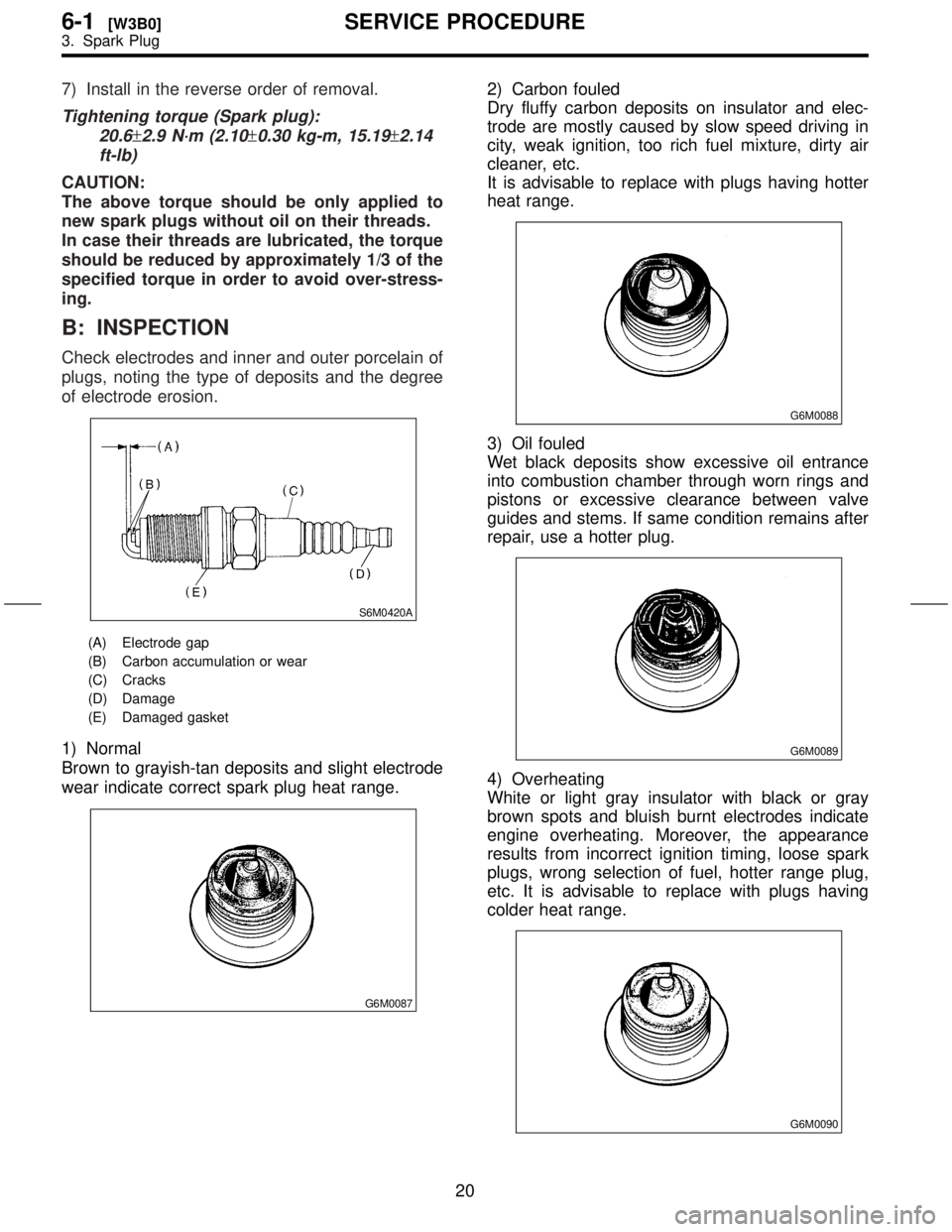
Check electrodes and inner and outer porcelain of
plugs, noting the type of deposits and the degree
of electrode erosion.
S6M0420A
(A) Electrode gap
(B) Carbon accumulation or wear
(C) Cracks
(D) Damage
(E) Damaged gasket
1) Normal
Brown to grayish-tan deposits and slight electrode
wear indicate correct spark plug heat range.
G6M0087
2) Carbon fouled
Dry fluffy carbon deposits on insulator and elec-
trode are mostly caused by slow speed driving in
city, weak ignition, too rich fuel mixture, dirty air
cleaner, etc.
It is advisable to replace with plugs having hotter
heat range.
G6M0088
3) Oil fouled
Wet black deposits show excessive oil entrance
into combustion chamber through worn rings and
pistons or excessive clearance between valve
guides and stems. If same condition remains after
repair, use a hotter plug.
G6M0089
4) Overheating
White or light gray insulator with black or gray
brown spots and bluish burnt electrodes indicate
engine overheating. Moreover, the appearance
results from incorrect ignition timing, loose spark
plugs, wrong selection of fuel, hotter range plug,
etc. It is advisable to replace with plugs having
colder heat range.
G6M0090
20
6-1[W3B0]SERVICE PROCEDURE
3. Spark Plug
Page 315 of 345

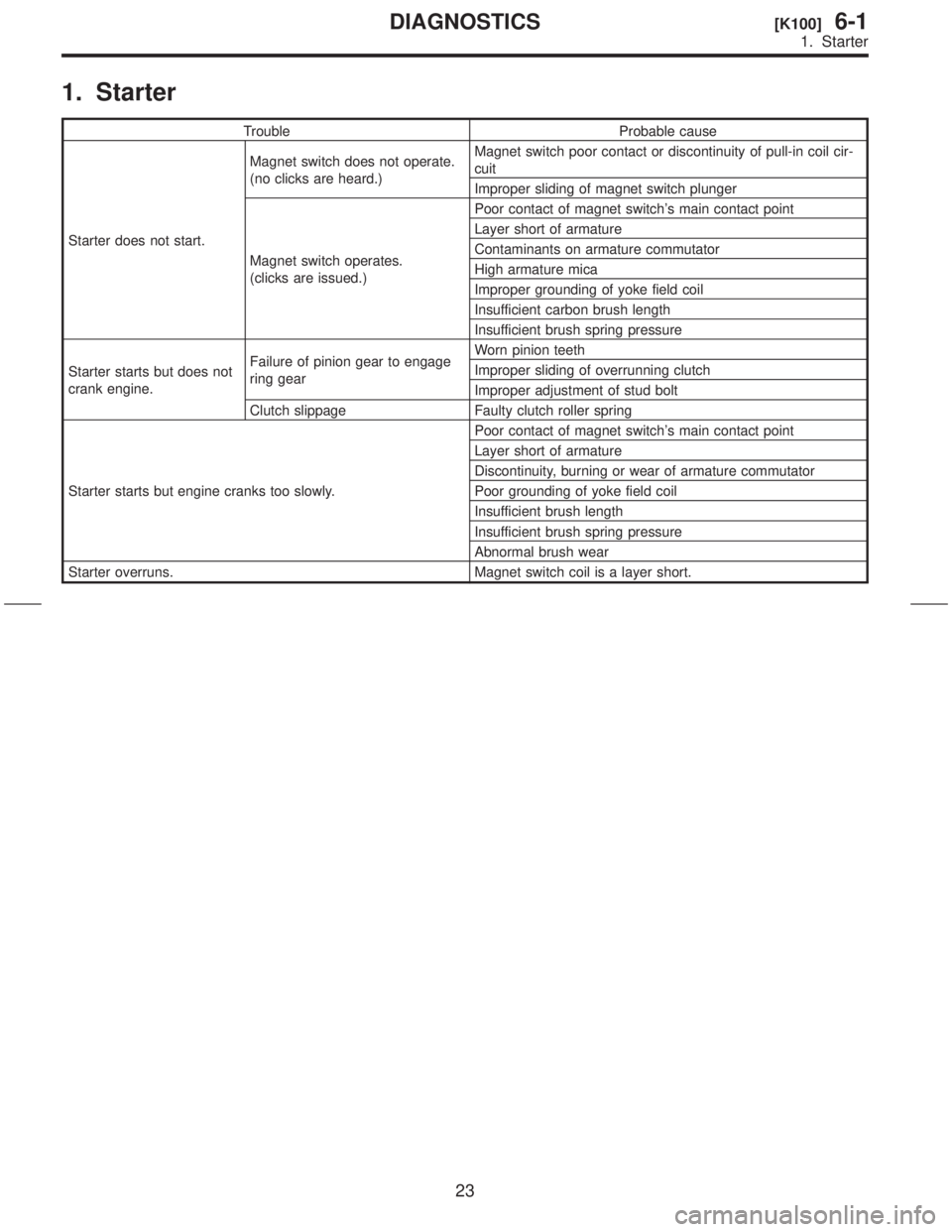
1. Starter
Trouble Probable cause
Starter does not start.Magnet switch does not operate.
(no clicks are heard.)Magnet switch poor contact or discontinuity of pull-in coil cir-
cuit
Improper sliding of magnet switch plunger
Magnet switch operates.
(clicks are issued.)Poor contact of magnet switch's main contact point
Layer short of armature
Contaminants on armature commutator
High armature mica
Improper grounding of yoke field coil
Insufficient carbon brush length
Insufficient brush spring pressure
Starter starts but does not
crank engine.Failure of pinion gear to engage
ring gearWorn pinion teeth
Improper sliding of overrunning clutch
Improper adjustment of stud bolt
Clutch slippage Faulty clutch roller spring
Starter starts but engine cranks too slowly.Poor contact of magnet switch's main contact point
Layer short of armature
Discontinuity, burning or wear of armature commutator
Poor grounding of yoke field coil
Insufficient brush length
Insufficient brush spring pressure
Abnormal brush wear
Starter overruns. Magnet switch coil is a layer short.
23
[K100]6-1DIAGNOSTICS
1. Starter
Page 332 of 345
3. REAR WIPER RELAY
1) Connect battery to terminal No. 1 and ground
terminal No. 2.
2) Check continuity between terminals.
When current
flowsBetween terminals
No. 3 and No. 4Continuity does
not exist.
Between terminals
No. 3 and No. 5Continuity exists.
When current
does not flowBetween terminals
No. 3 and No. 4Continuity exists.
Between terminals
No. 3 and No. 5Continuity does
not exist.
Between terminals
No. 1 and No. 2Continuity exists.
S6M0075B
7. Rear Window Defogger
A: INSPECTION
1. HEAT WIRES
1) Start the engine so that battery is being
charged.
2) Turn defogger switch to ON.
3) Check each heat wire at its center position for
discontinuity by setting direct current voltmeter.
NOTE:
INormal indication is about 6 volts.
G6M0135
IWhen measuring voltage, wind a piece of tin foil
around the tip of the tester probe and press the foil
against the wire with your finger.
G6M0136
14
6-2[W6C3]SERVICE PROCEDURE
7. Rear Window Defogger
Page 333 of 345
3. REAR WIPER RELAY
1) Connect battery to terminal No. 1 and ground
terminal No. 2.
2) Check continuity between terminals.
When current
flowsBetween terminals
No. 3 and No. 4Continuity does
not exist.
Between terminals
No. 3 and No. 5Continuity exists.
When current
does not flowBetween terminals
No. 3 and No. 4Continuity exists.
Between terminals
No. 3 and No. 5Continuity does
not exist.
Between terminals
No. 1 and No. 2Continuity exists.
S6M0075B
7. Rear Window Defogger
A: INSPECTION
1. HEAT WIRES
1) Start the engine so that battery is being
charged.
2) Turn defogger switch to ON.
3) Check each heat wire at its center position for
discontinuity by setting direct current voltmeter.
NOTE:
INormal indication is about 6 volts.
G6M0135
IWhen measuring voltage, wind a piece of tin foil
around the tip of the tester probe and press the foil
against the wire with your finger.
G6M0136
14
6-2[W6C3]SERVICE PROCEDURE
7. Rear Window Defogger