1999 SUBARU FORESTER Body system
[x] Cancel search: Body systemPage 15 of 345
![SUBARU FORESTER 1999 Service Repair Manual Trouble code/
Contents of troublesMemory function Contents of diagnosis Index No.
46 Provided.ISide airbag harness (LH) is faulty.
IAirbag control module is faulty.<Ref. to 5-5 [T5P0].>
51 Provided.IS SUBARU FORESTER 1999 Service Repair Manual Trouble code/
Contents of troublesMemory function Contents of diagnosis Index No.
46 Provided.ISide airbag harness (LH) is faulty.
IAirbag control module is faulty.<Ref. to 5-5 [T5P0].>
51 Provided.IS](/manual-img/17/57427/w960_57427-14.png)
Trouble code/
Contents of troublesMemory function Contents of diagnosis Index No.
46 Provided.ISide airbag harness (LH) is faulty.
IAirbag control module is faulty.
51 Provided.ISide airbag sensor (RH) is faulty.
ISide airbag harness (RH) is faulty.
IAirbag control module is faulty.
52 Provided.ISide airbag sensor (LH) is faulty.
ISide airbag harness (LH) is faulty.
IAirbag control module is faulty.
53 Provided. Side airbag sensor (RH) is faulty.
54 Provided. Side airbag sensor (LH) is faulty.
55 Provided. Side airbag module is inflated.
Airbag warning light remains
on.Not provided.IAirbag warning light is faulty.
IAirbag control module to airbag warning light
harness circuit is shorted or open.
IGrounding circuit is faulty.
IAirbag control module is faulty.
I(AB1) and (B31) are not connected properly.
I(AB6) is not connected properly to airbag control
module.
Airbag warning light remains
off.Not provided.IFuse No. 5 (in main fuse box) is blown.
IBody harness circuit is open.
IAirbag warning light is faulty.
IAirbag main harness is faulty.
IAirbag control module is faulty.
Warning light indicates
trouble code, then normal
code. (Flashing trouble
code.)Provided. Airbag system component parts are faulty.
Warning light indicates
trouble code, then normal
code. (Flashing normal
code.)Not provided.IAirbag connector is faulty.
IFuse No. 11 (in joint box) is blown.
IAirbag main harness is faulty.
IAirbag control module is faulty.
IBody harness is faulty.
2. HOW TO READ TROUBLE CODES
The AIRBAG warning light flashes a code corresponding to the faulty parts.
The long segment (1.2 sec on) indicates a ªtenº, and the short segment (0.3 sec on) indicates a ªoneº.
B5M0117A
16
5-5[T5A2]DIAGNOSTICS
5. Diagnostics Chart with Trouble Code
Page 23 of 345
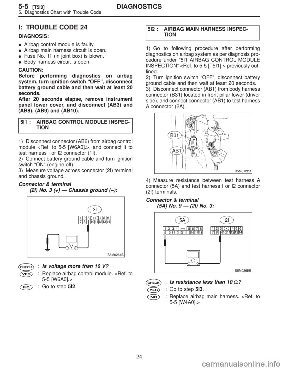
I: TROUBLE CODE 24
DIAGNOSIS:
IAirbag control module is faulty.
IAirbag main harness circuit is open.
IFuse No. 11 (in joint box) is blown.
IBody harness circuit is open.
CAUTION:
Before performing diagnostics on airbag
system, turn ignition switch ªOFFº, disconnect
battery ground cable and then wait at least 20
seconds.
After 20 seconds elapse, remove instrument
panel lower cover, and disconnect (AB3) and
(AB8), (AB9) and (AB10).
5I1 : AIRBAG CONTROL MODULE INSPEC-
TION
1) Disconnect connector (AB6) from airbag control
module
test harness I or I2 connector (1I).
2) Connect battery ground cable and turn ignition
switch ªONº (engine off).
3) Measure voltage across connector (2I) terminal
and chassis ground.
Connector & terminal
(2I) No. 3 (+) Ð Chassis ground (þ):
S5M0264B
:Is voltage more than 10 V?
: Replace airbag control module.
: Go to step5I2.5I2 : AIRBAG MAIN HARNESS INSPEC-
TION
1) Go to following procedure after performing
diagnostics on airbag system as per diagnosis pro-
cedure under ª5I1 AIRBAG CONTROL MODULE
INSPECTIONº
lined.
2) Turn ignition switch ªOFFº, disconnect battery
ground cable and then wait at least 20 seconds.
3) Disconnect connector (AB1) from body harness
connector (B31) located in front pillar lower (driver
side), and connect connector (AB1) to test harness
A connector (2A).
B5M0122B
4) Measure resistance between test harness A
connector (5A) and test harness I or I2 connector
(2I) terminals.
Connector & terminal
(5A) No. 9 Ð (2I) No. 3:
S5M0265B
:Is resistance less than 10W?
: Go to step5I3.
: Replace airbag main harness.
24
5-5[T5I0]DIAGNOSTICS
5. Diagnostics Chart with Trouble Code
Page 25 of 345
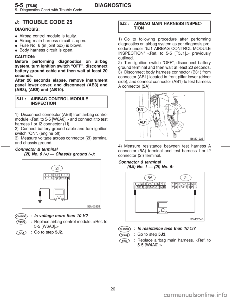
J: TROUBLE CODE 25
DIAGNOSIS:
IAirbag control module is faulty.
IAirbag main harness circuit is open.
IFuse No. 6 (in joint box) is blown.
IBody harness circuit is open.
CAUTION:
Before performing diagnostics on airbag
system, turn ignition switch ªOFFº, disconnect
battery ground cable and then wait at least 20
seconds.
After 20 seconds elapse, remove instrument
panel lower cover, and disconnect (AB3) and
(AB8), (AB9) and (AB10).
5J1 : AIRBAG CONTROL MODULE
INSPECTION
1) Disconnect connector (AB6) from airbag control
module
harness I or I2 connector (1I).
2) Connect battery ground cable and turn ignition
switch ªONº. (engine off)
3) Measure voltage across connector (2I) terminal
and chassis ground.
Connector & terminal
(2I) No. 6 (+) Ð Chassis ground (þ):
S5M0253B
:Is voltage more than 10 V?
: Replace airbag control module.
: Go to step5J2.5J2 : AIRBAG MAIN HARNESS INSPEC-
TION
1) Go to following procedure after performing
diagnostics on airbag system as per diagnosis pro-
cedure under ª5J1 AIRBAG CONTROL MODULE
INSPECTIONº
outlined.
2) Turn ignition switch ªOFFº, disconnect battery
ground terminal and then wait at least 20 seconds.
3) Disconnect body harness connector (B31) from
connector (AB1) located in front pillar lower (driver
side), and connect connector (AB1) to test harness
A connector (2A).
B5M0122B
4) Measure resistance between test harness A
connector (5A) terminal and test harness I or I2
connector (2I) terminal.
Connector & terminal
(5A) No. 1 Ð (2I) No. 6:
S5M0254B
:Is resistance less than 10W?
: Go to step5J3.
: Replace airbag main harness.
26
5-5[T5J0]DIAGNOSTICS
5. Diagnostics Chart with Trouble Code
Page 57 of 345
![SUBARU FORESTER 1999 Service Repair Manual 5V8 : INSPECTION OF AIRBAG MAIN HAR-
NESS
1) Connect connectors (AB1) and (B31). Discon-
nect connector (AB6) from airbag control module
<Ref. to 5-5 [W6A0].>, and connect it to test har-
ness I or I2 SUBARU FORESTER 1999 Service Repair Manual 5V8 : INSPECTION OF AIRBAG MAIN HAR-
NESS
1) Connect connectors (AB1) and (B31). Discon-
nect connector (AB6) from airbag control module
<Ref. to 5-5 [W6A0].>, and connect it to test har-
ness I or I2](/manual-img/17/57427/w960_57427-56.png)
5V8 : INSPECTION OF AIRBAG MAIN HAR-
NESS
1) Connect connectors (AB1) and (B31). Discon-
nect connector (AB6) from airbag control module
ness I or I2 connector (1I).
2) Measure resistance between each test harness
I or I2 connector (2I) terminal and chassis ground.
Connector & terminal
(2I) No. 9 (+) Ð Chassis ground (þ):
S5M0271B
:Is resistance less than 10W?
: Go to step5V9.
: Replace airbag main harness.
5V9 : INSPECTION OF AIRBAG MAIN HAR-
NESS
Measure resistance between each test harness I
or I2 connector (2I) terminal and chassis ground.
Connector & terminal
(2I) No. 10 (+) Ð Chassis ground (þ):
S5M0272B
:Is resistance less than 10W?
: Replace airbag control module.
: Replace airbag main harness.
W: AIRBAG WARNING LIGHT
REMAINS OFF.
DIAGNOSIS:
IFuse No. 5 (in main fuse box) is blown.
IBody harness circuit is open.
IAirbag warning light is faulty.
IAirbag main harness is faulty.
IAirbag control module is faulty.
CAUTION:
Before performing diagnostics on airbag
system, turn ignition switch ªOFFº, disconnect
battery ground terminal, and then wait at least
20 seconds.
5W1 : FUSE NO. 5 (IN MAIN FUSE BOX)
INSPECTION
Remove and visually check fuse No. 5 (In main
fuse box).
S5M0273A
:Is fuse No. 5 blown?
: Replace fuse No. 5. If fuse No. 5 blows
again, Go to step5W2.
: Go to step5W2.
5W2 : BODY HARNESS INSPECTION
Turn ignition switch ªONº (engine off) to make sure
other warning lights (in combination meter) illumi-
nate.
:Do all the warning lights (in combina-
tion meter) except airbag warning
light come on?
: Go to step5W3.
: Repair body harness.
58
5-5[T5V8]DIAGNOSTICS
5. Diagnostics Chart with Trouble Code
Page 59 of 345
X: WARNING LIGHT INDICATES
TROUBLE CODE, THEN NORMAL
CODE. (FLASHING TROUBLE
CODE.)
DIAGNOSIS:
Airbag system component parts are faulty.
CAUTION:
Before performing diagnostics on airbag
system, turn ignition switch ªOFFº, disconnect
battery ground cable, and then wait at least 20
seconds.5X1 : AIRBAG COMPONENT PARTS
APPEARANCE INSPECTION
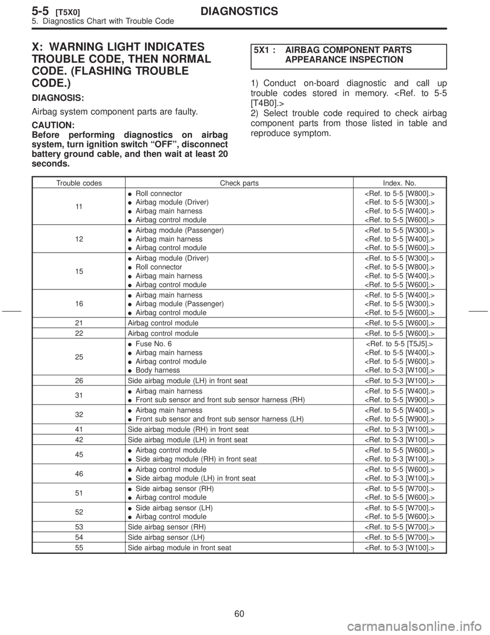
1) Conduct on-board diagnostic and call up
trouble codes stored in memory.
2) Select trouble code required to check airbag
component parts from those listed in table and
reproduce symptom.
Trouble codes Check parts Index. No.
11IRoll connector
IAirbag module (Driver)
IAirbag main harness
IAirbag control module
12IAirbag module (Passenger)
IAirbag main harness
IAirbag control module
15IAirbag module (Driver)
IRoll connector
IAirbag main harness
IAirbag control module
16IAirbag main harness
IAirbag module (Passenger)
IAirbag control module
21 Airbag control module
22 Airbag control module
25IFuse No. 6
IAirbag main harness
IAirbag control module
IBody harness
26 Side airbag module (LH) in front seat
31IAirbag main harness
IFront sub sensor and front sub sensor harness (RH)
32IAirbag main harness
IFront sub sensor and front sub sensor harness (LH)
41 Side airbag module (RH) in front seat
42 Side airbag module (LH) in front seat
45IAirbag control module
ISide airbag module (RH) in front seat
46IAirbag control module
ISide airbag module (LH) in front seat
51ISide airbag sensor (RH)
IAirbag control module
52ISide airbag sensor (LH)
IAirbag control module
53 Side airbag sensor (RH)
54 Side airbag sensor (LH)
55 Side airbag module in front seat
60
5-5[T5X0]DIAGNOSTICS
5. Diagnostics Chart with Trouble Code
Page 60 of 345
3) Conduct appearance inspection on parts
selected.
NOTE:
Also check connector terminals, wiring harness,
case, etc. for damage.
:Is there anything unusual about the
appearance of airbag component
parts?
: Replace faulty airbag component parts.
: Go to step5X2.
5X2 : AIRBAG COMPONENT PARTS
VIBRATION INSPECTION
1) Gently shake check parts (to determine faults.).
2) To check airbag module or roll connector, turn
and tilt steering wheel.
CAUTION:
Do not shake or vibrate airbag control module.
:Does the component malfunction
again when shaking?
: Replace faulty airbag component parts.
: Go to step5X3.
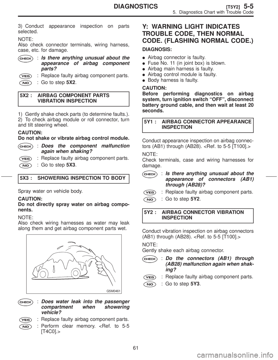
5X3 : SHOWERING INSPECTION TO BODY
Spray water on vehicle body.
CAUTION:
Do not directly spray water on airbag compo-
nents.
NOTE:
Also check wiring harnesses as water may leak
along them and get airbag component parts wet.
G5M0461
:Does water leak into the passenger
compartment when showering
vehicle?
: Replace faulty airbag component parts.
: Perform clear memory.
Y: WARNING LIGHT INDICATES
TROUBLE CODE, THEN NORMAL
CODE. (FLASHING NORMAL CODE.)
DIAGNOSIS:
IAirbag connector is faulty.
IFuse No. 11 (in joint box) is blown.
IAirbag main harness is faulty.
IAirbag control module is faulty.
IBody harness is faulty.
CAUTION:
Before performing diagnostics on airbag
system, turn ignition switch ªOFFº, disconnect
battery ground cable, and then wait at least 20
seconds.
5Y1 : AIRBAG CONNECTOR APPEARANCE
INSPECTION
Conduct appearance inspection on airbag connec-
tors (AB1) through (AB28).
NOTE:
Check terminals, case and wiring harnesses for
damage.
:Is there anything unusual about the
appearance of connectors (AB1)
through (AB28)?
: Replace faulty airbag component parts.
: Go to step5Y2.
5Y2 : AIRBAG CONNECTOR VIBRATION
INSPECTION
Conduct vibration inspection on airbag connectors
(AB1) through (AB28).
NOTE:
Gently shake each airbag connector.
:Do the connectors (AB1) through
(AB28) malfunction again when shak-
ing?
: Replace faulty airbag component parts.
: Go to step5Y3.
61
[T5Y2]5-5DIAGNOSTICS
5. Diagnostics Chart with Trouble Code
Page 115 of 345
4. Keyless Entry System
A: PRECAUTION
1. SUPPLEMENTAL RESTRAINT SYSTEM
ªAIRBAGº
Airbag system wiring harness is routed near the
keyless entry control module.
CAUTION:
IAll airbag system wiring harness and con-
nectors are yellow. Do not use electrical test
equipment on these circuits.
IBe careful not to damage airbag system wir-
ing harness when servicing the keyless entry
control module.
B: PRE-INSPECTION
1. POWER DOOR LOCK
4B11 : CHECK POWER DOOR LOCK.
Perform lock and unlock with door lock switch.
:Does the power door lock function
normally?
: Go to step4B21.
: Repair power door lock.
2. TRANSMITTER
4B21 : CHECK TRANSMITTER BATTERY.
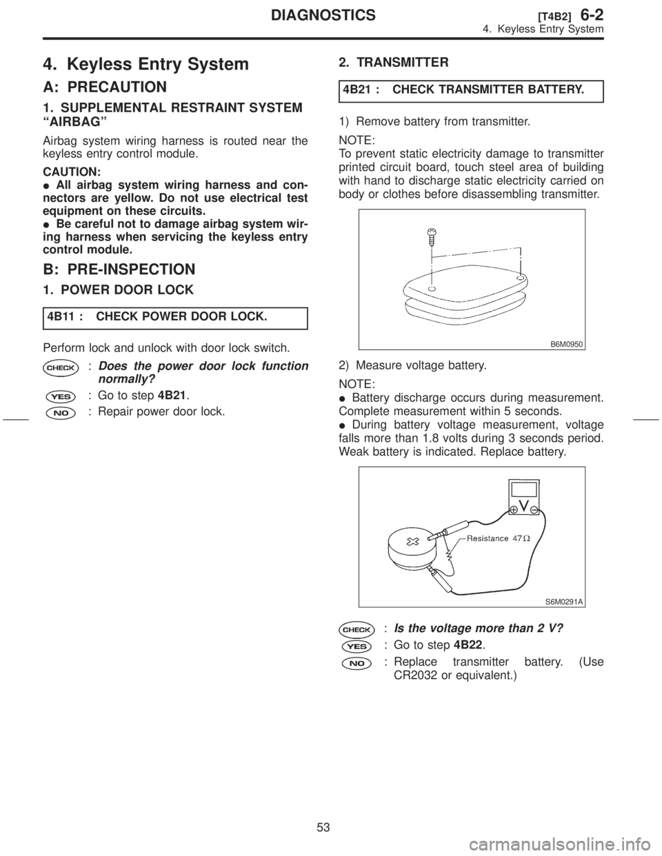
1) Remove battery from transmitter.
NOTE:
To prevent static electricity damage to transmitter
printed circuit board, touch steel area of building
with hand to discharge static electricity carried on
body or clothes before disassembling transmitter.
B6M0950
2) Measure voltage battery.
NOTE:
IBattery discharge occurs during measurement.
Complete measurement within 5 seconds.
IDuring battery voltage measurement, voltage
falls more than 1.8 volts during 3 seconds period.
Weak battery is indicated. Replace battery.
S6M0291A
:Is the voltage more than 2 V?
: Go to step4B22.
: Replace transmitter battery. (Use
CR2032 or equivalent.)
53
[T4B2]6-2DIAGNOSTICS
4. Keyless Entry System
Page 157 of 345
1. Precaution
A: SUPPLEMENTAL RESTRAINT
SYSTEM ªAIRBAGº
Airbag system wiring harness is routed on and
along body panels.
CAUTION:
IAll airbag system wiring harness and con-
nectors are yellow. Do not use electrical test
equipment on these circuit.
IBe careful not to damage airbag system wir-
ing harness when repairing the body panel.
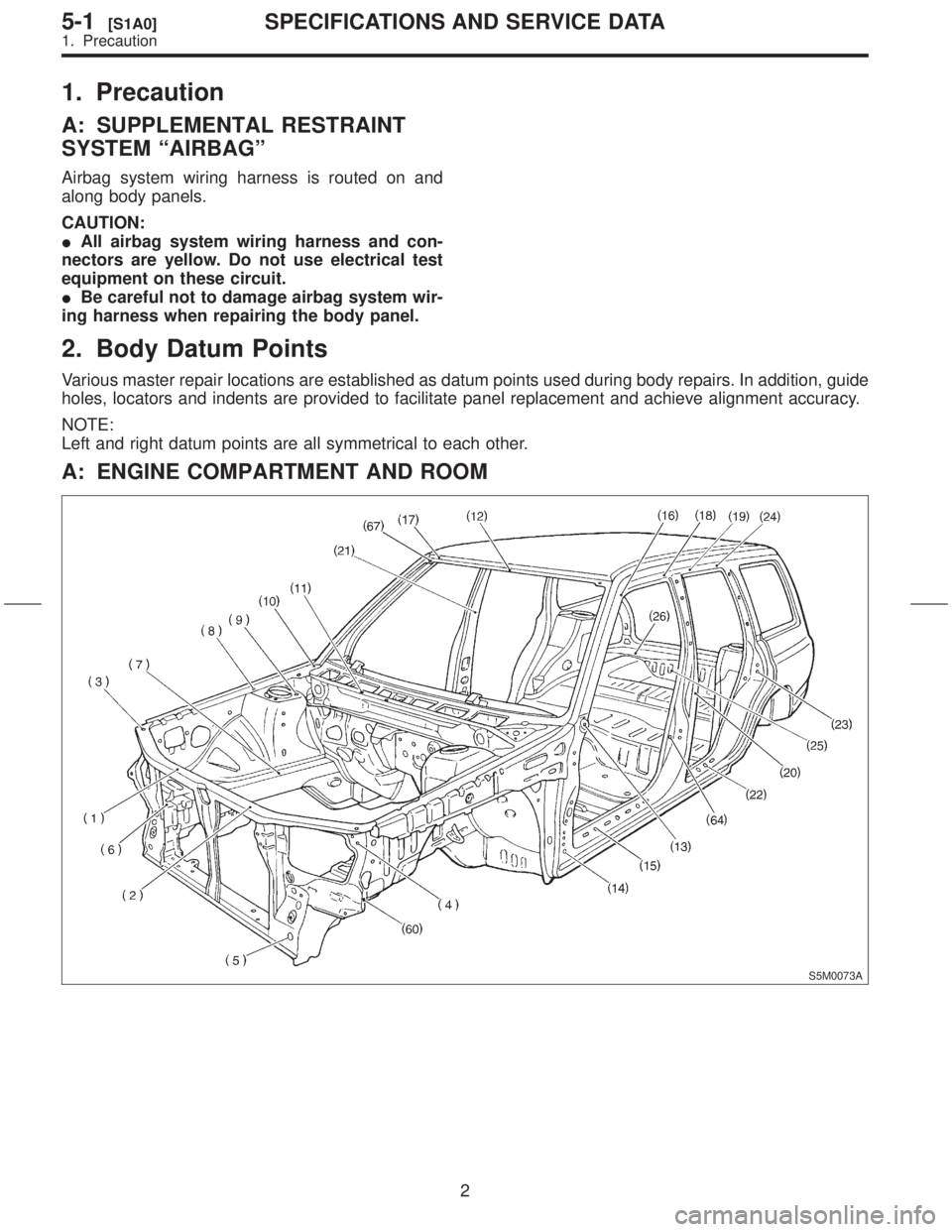
2. Body Datum Points
Various master repair locations are established as datum points used during body repairs. In addition, guide
holes, locators and indents are provided to facilitate panel replacement and achieve alignment accuracy.
NOTE:
Left and right datum points are all symmetrical to each other.
A: ENGINE COMPARTMENT AND ROOM
S5M0073A
2
5-1[S1A0]SPECIFICATIONS AND SERVICE DATA
1. Precaution