Page 171 of 345
3. Datum Dimensions
Use a tram tracking gauge to measure all dimen-
sions. If a measuring tape is used, be extremely
careful because it tends to deflect or twist, which
results in a false reading.
G5M0122
NOTE:
IA suffix character ªRº or ªLº refers to the right or
the left.
IAll dimensions refer to the distance between the
centers of holes measured in a straight line.
IEach dimension indicates a projected dimension
between hole centers.
15
[S300]5-1SPECIFICATIONS AND SERVICE DATA
3. Datum Dimensions
Page 172 of 345

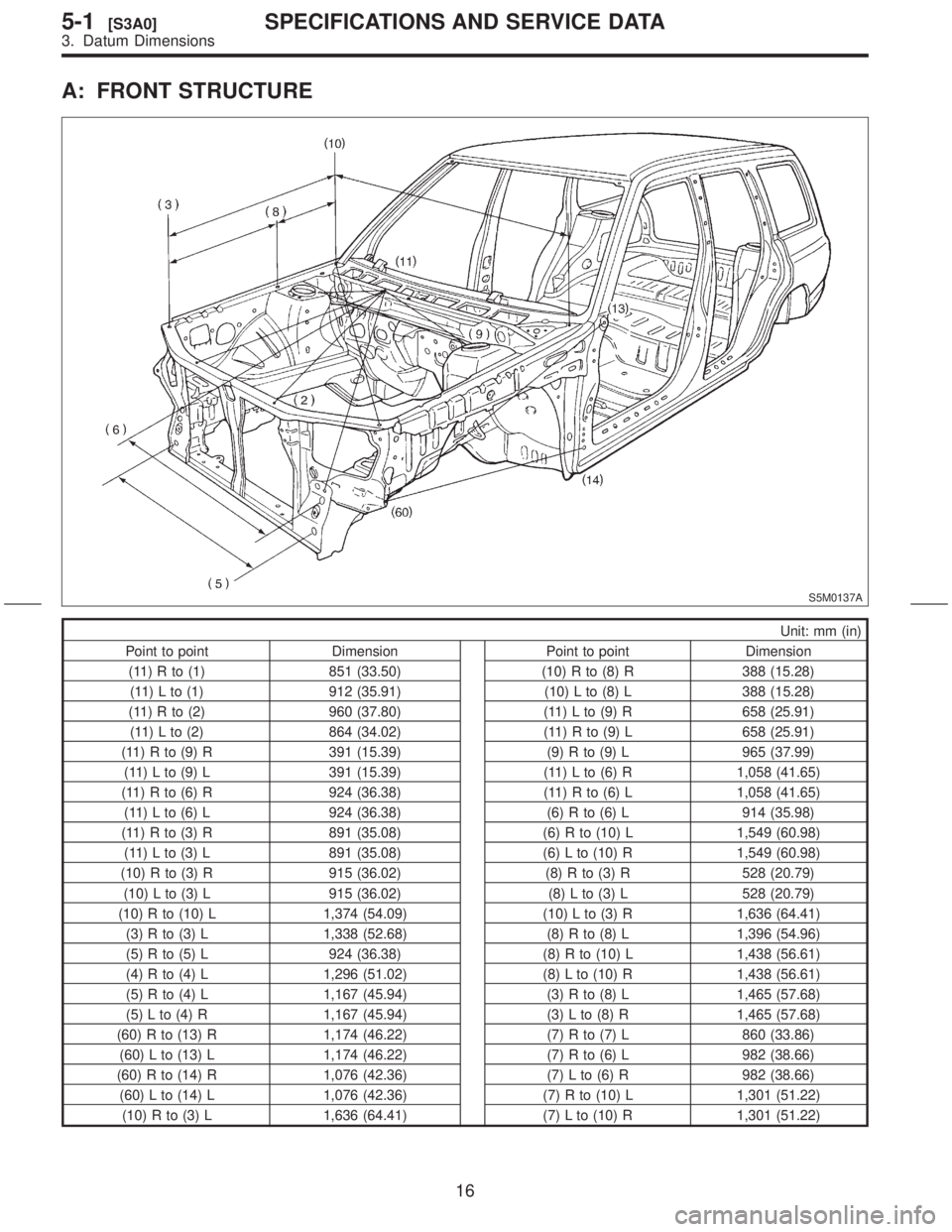
A: FRONT STRUCTURE
S5M0137A
Unit: mm (in)
Point to point Dimension Point to point Dimension
(11) R to (1) 851 (33.50) (10) R to (8) R 388 (15.28)
(11) L to (1) 912 (35.91) (10) L to (8) L 388 (15.28)
(11) R to (2) 960 (37.80) (11) L to (9) R 658 (25.91)
(11) L to (2) 864 (34.02) (11) R to (9) L 658 (25.91)
(11) R to (9) R 391 (15.39) (9) R to (9) L 965 (37.99)
(11) L to (9) L 391 (15.39) (11) L to (6) R 1,058 (41.65)
(11) R to (6) R 924 (36.38) (11) R to (6) L 1,058 (41.65)
(11) L to (6) L 924 (36.38) (6) R to (6) L 914 (35.98)
(11) R to (3) R 891 (35.08) (6) R to (10) L 1,549 (60.98)
(11) L to (3) L 891 (35.08) (6) L to (10) R 1,549 (60.98)
(10) R to (3) R 915 (36.02) (8) R to (3) R 528 (20.79)
(10) L to (3) L 915 (36.02) (8) L to (3) L 528 (20.79)
(10) R to (10) L 1,374 (54.09) (10) L to (3) R 1,636 (64.41)
(3) R to (3) L 1,338 (52.68) (8) R to (8) L 1,396 (54.96)
(5) R to (5) L 924 (36.38) (8) R to (10) L 1,438 (56.61)
(4) R to (4) L 1,296 (51.02) (8) L to (10) R 1,438 (56.61)
(5) R to (4) L 1,167 (45.94) (3) R to (8) L 1,465 (57.68)
(5) L to (4) R 1,167 (45.94) (3) L to (8) R 1,465 (57.68)
(60) R to (13) R 1,174 (46.22) (7) R to (7) L 860 (33.86)
(60) L to (13) L 1,174 (46.22) (7) R to (6) L 982 (38.66)
(60) R to (14) R 1,076 (42.36) (7) L to (6) R 982 (38.66)
(60) L to (14) L 1,076 (42.36) (7) R to (10) L 1,301 (51.22)
(10) R to (3) L 1,636 (64.41) (7) L to (10) R 1,301 (51.22)
16
5-1[S3A0]SPECIFICATIONS AND SERVICE DATA
3. Datum Dimensions
Page 173 of 345
B: CENTER STRUCTURE
S5M0138A
17
[S3B0]5-1SPECIFICATIONS AND SERVICE DATA
3. Datum Dimensions
Page 174 of 345
C: DOORS AND PASSENGER COMPARTMENT
S5M0139A
18
5-1[S3C0]SPECIFICATIONS AND SERVICE DATA
3. Datum Dimensions
Page 175 of 345

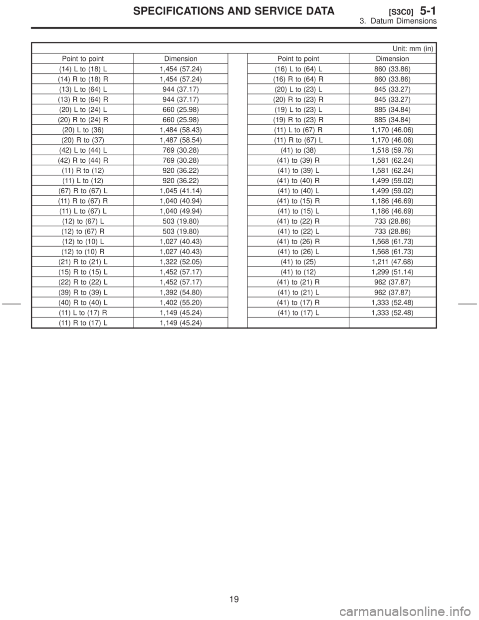
Unit: mm (in)
Point to point Dimension Point to point Dimension
(14) L to (18) L 1,454 (57.24) (16) L to (64) L 860 (33.86)
(14) R to (18) R 1,454 (57.24) (16) R to (64) R 860 (33.86)
(13) L to (64) L 944 (37.17) (20) L to (23) L 845 (33.27)
(13) R to (64) R 944 (37.17) (20) R to (23) R 845 (33.27)
(20) L to (24) L 660 (25.98) (19) L to (23) L 885 (34.84)
(20) R to (24) R 660 (25.98) (19) R to (23) R 885 (34.84)
(20) L to (36) 1,484 (58.43) (11) L to (67) R 1,170 (46.06)
(20) R to (37) 1,487 (58.54) (11) R to (67) L 1,170 (46.06)
(42) L to (44) L 769 (30.28) (41) to (38) 1,518 (59.76)
(42) R to (44) R 769 (30.28) (41) to (39) R 1,581 (62.24)
(11) R to (12) 920 (36.22) (41) to (39) L 1,581 (62.24)
(11) L to (12) 920 (36.22) (41) to (40) R 1,499 (59.02)
(67) R to (67) L 1,045 (41.14) (41) to (40) L 1,499 (59.02)
(11) R to (67) R 1,040 (40.94) (41) to (15) R 1,186 (46.69)
(11) L to (67) L 1,040 (49.94) (41) to (15) L 1,186 (46.69)
(12) to (67) L 503 (19.80) (41) to (22) R 733 (28.86)
(12) to (67) R 503 (19.80) (41) to (22) L 733 (28.86)
(12) to (10) L 1,027 (40.43) (41) to (26) R 1,568 (61.73)
(12) to (10) R 1,027 (40.43) (41) to (26) L 1,568 (61.73)
(21) R to (21) L 1,322 (52.05) (41) to (25) 1,211 (47.68)
(15) R to (15) L 1,452 (57.17) (41) to (12) 1,299 (51.14)
(22) R to (22) L 1,452 (57.17) (41) to (21) R 962 (37.87)
(39) R to (39) L 1,392 (54.80) (41) to (21) L 962 (37.87)
(40) R to (40) L 1,402 (55.20) (41) to (17) R 1,333 (52.48)
(11) L to (17) R 1,149 (45.24) (41) to (17) L 1,333 (52.48)
(11) R to (17) L 1,149 (45.24)
19
[S3C0]5-1SPECIFICATIONS AND SERVICE DATA
3. Datum Dimensions
Page 176 of 345

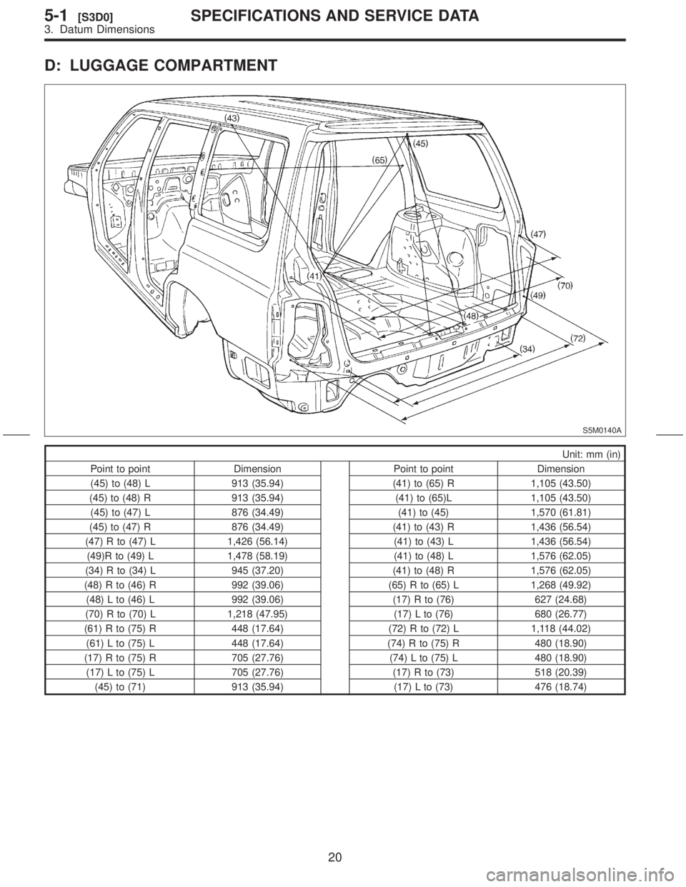
D: LUGGAGE COMPARTMENT
S5M0140A
Unit: mm (in)
Point to point Dimension Point to point Dimension
(45) to (48) L 913 (35.94) (41) to (65) R 1,105 (43.50)
(45) to (48) R 913 (35.94) (41) to (65)L 1,105 (43.50)
(45) to (47) L 876 (34.49) (41) to (45) 1,570 (61.81)
(45) to (47) R 876 (34.49) (41) to (43) R 1,436 (56.54)
(47) R to (47) L 1,426 (56.14) (41) to (43) L 1,436 (56.54)
(49)R to (49) L 1,478 (58.19) (41) to (48) L 1,576 (62.05)
(34) R to (34) L 945 (37.20) (41) to (48) R 1,576 (62.05)
(48) R to (46) R 992 (39.06) (65) R to (65) L 1,268 (49.92)
(48) L to (46) L 992 (39.06) (17) R to (76) 627 (24.68)
(70) R to (70) L 1,218 (47.95) (17) L to (76) 680 (26.77)
(61) R to (75) R 448 (17.64) (72) R to (72) L 1,118 (44.02)
(61) L to (75) L 448 (17.64) (74) R to (75) R 480 (18.90)
(17) R to (75) R 705 (27.76) (74) L to (75) L 480 (18.90)
(17) L to (75) L 705 (27.76) (17) R to (73) 518 (20.39)
(45) to (71) 913 (35.94) (17) L to (73) 476 (18.74)
20
5-1[S3D0]SPECIFICATIONS AND SERVICE DATA
3. Datum Dimensions
Page 177 of 345
4. Datum Points and Dimensions Concerning On-Board Aiming
Adjustment
If headlight aiming is misaligned due to a damaged body panel, repair headlight mating surface using body
and headlight datum points as a guide.
NOTE:
It is recommended to conduct on-board aiming adjustment with headlights turned OFF. If turned ON dur-
ing the adjustment, the duration should be within two minutes.
S5M0141A
Unit: mm (in)
Point to point Dimension Point to point Dimension
(11) to (A) 890.6 (35.06) (11) to (C) 1,087.7 (42.82)
(11) to (B) 913.4 (35.96) (11) to (D) 1,023.7 (40.30)
21
[S400]5-1SPECIFICATIONS AND SERVICE DATA
4. Datum Points and Dimensions Concerning On-Board Aiming Adjustment
Page 228 of 345

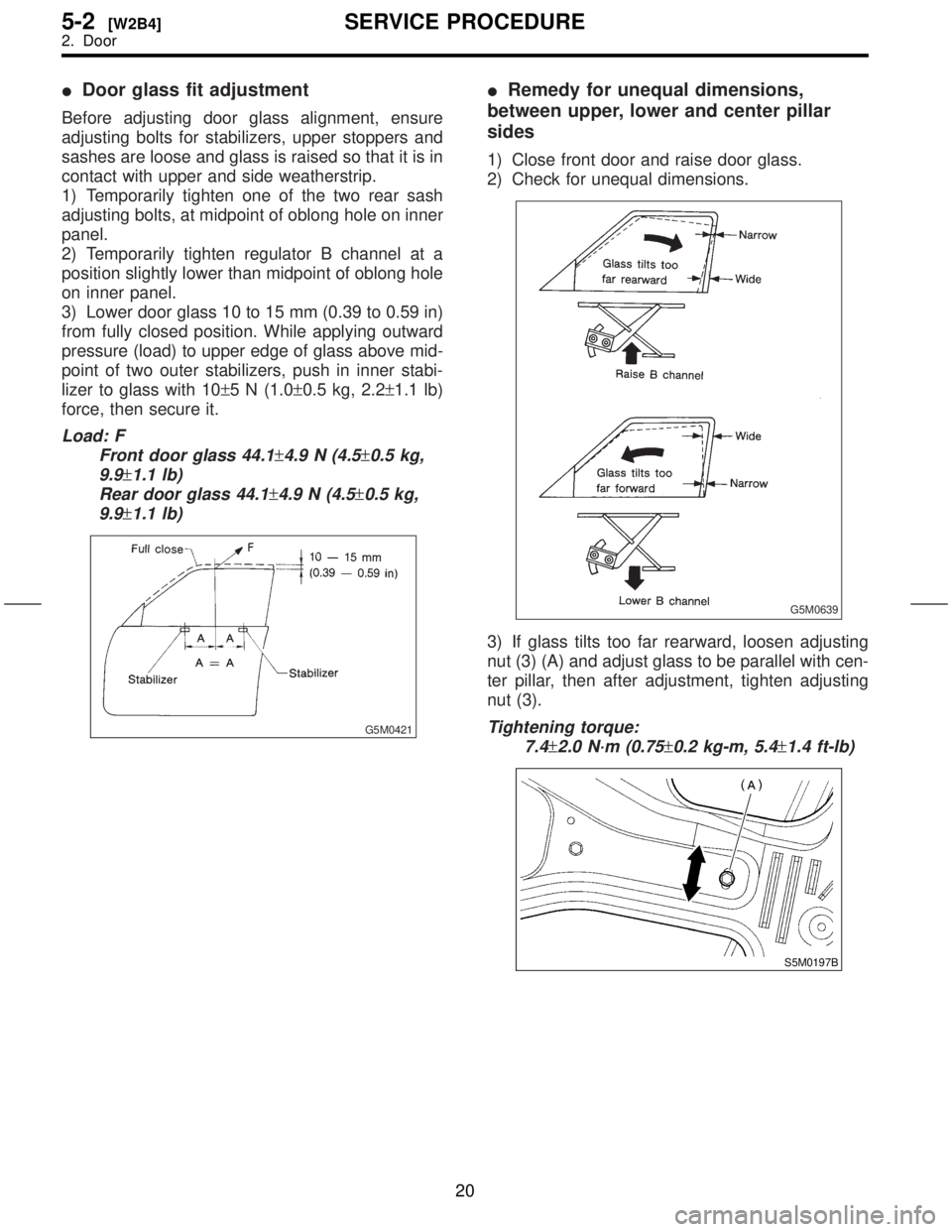
IDoor glass fit adjustment
Before adjusting door glass alignment, ensure
adjusting bolts for stabilizers, upper stoppers and
sashes are loose and glass is raised so that it is in
contact with upper and side weatherstrip.
1) Temporarily tighten one of the two rear sash
adjusting bolts, at midpoint of oblong hole on inner
panel.
2) Temporarily tighten regulator B channel at a
position slightly lower than midpoint of oblong hole
on inner panel.
3) Lower door glass 10 to 15 mm (0.39 to 0.59 in)
from fully closed position. While applying outward
pressure (load) to upper edge of glass above mid-
point of two outer stabilizers, push in inner stabi-
lizer to glass with 10±5 N (1.0±0.5 kg, 2.2±1.1 lb)
force, then secure it.
Load: F
Front door glass 44.1
±4.9 N (4.5±0.5 kg,
9.9
±1.1 lb)
Rear door glass 44.1
±4.9 N (4.5±0.5 kg,
9.9
±1.1 lb)
G5M0421
IRemedy for unequal dimensions,
between upper, lower and center pillar
sides
1) Close front door and raise door glass.
2) Check for unequal dimensions.
G5M0639
3) If glass tilts too far rearward, loosen adjusting
nut (3) (A) and adjust glass to be parallel with cen-
ter pillar, then after adjustment, tighten adjusting
nut (3).
Tightening torque:
7.4
±2.0 N´m (0.75±0.2 kg-m, 5.4±1.4 ft-lb)
S5M0197B
20
5-2[W2B4]SERVICE PROCEDURE
2. Door