Page 2051 of 2267
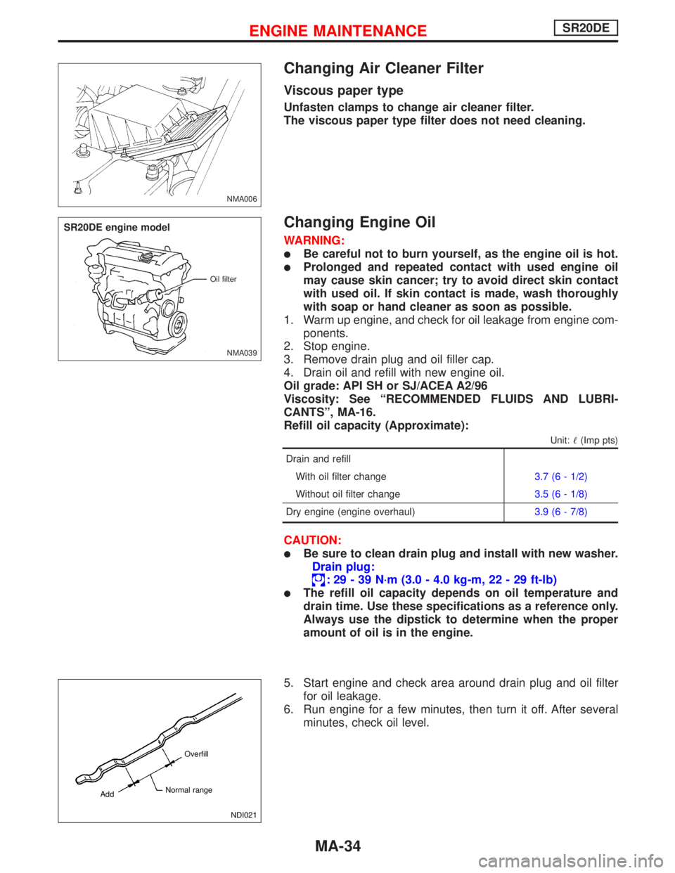
Changing Air Cleaner Filter
Viscous paper type
Unfasten clamps to change air cleaner filter.
The viscous paper type filter does not need cleaning.
Changing Engine Oil
WARNING:
�Be careful not to burn yourself, as the engine oil is hot.
�Prolonged and repeated contact with used engine oil
may cause skin cancer; try to avoid direct skin contact
with used oil. If skin contact is made, wash thoroughly
with soap or hand cleaner as soon as possible.
1. Warm up engine, and check for oil leakage from engine com-
ponents.
2. Stop engine.
3. Remove drain plug and oil filler cap.
4. Drain oil and refill with new engine oil.
Oil grade: API SH or SJ/ACEA A2/96
Viscosity: See“RECOMMENDED FLUIDS AND LUBRI-
CANTS”, MA-16.
Refill oil capacity (Approximate):
Unit:�(Imp pts)
Drain and refill
With oil filter change3.7 (6 - 1/2)
Without oil filter change3.5 (6 - 1/8)
Dry engine (engine overhaul)3.9 (6 - 7/8)
CAUTION:
�Be sure to clean drain plug and install with new washer.
Drain plug:
:29-39N·m (3.0 - 4.0 kg-m, 22 - 29 ft-lb)
�The refill oil capacity depends on oil temperature and
drain time. Use these specifications as a reference only.
Always use the dipstick to determine when the proper
amount of oil is in the engine.
5. Start engine and check area around drain plug and oil filter
for oil leakage.
6. Run engine for a few minutes, then turn it off. After several
minutes, check oil level.
NMA006
NMA039 Oil filter
SR20DE engine model
NDI021 Overfill
Normal range
Add
ENGINE MAINTENANCESR20DE
MA-34
Page 2062 of 2267
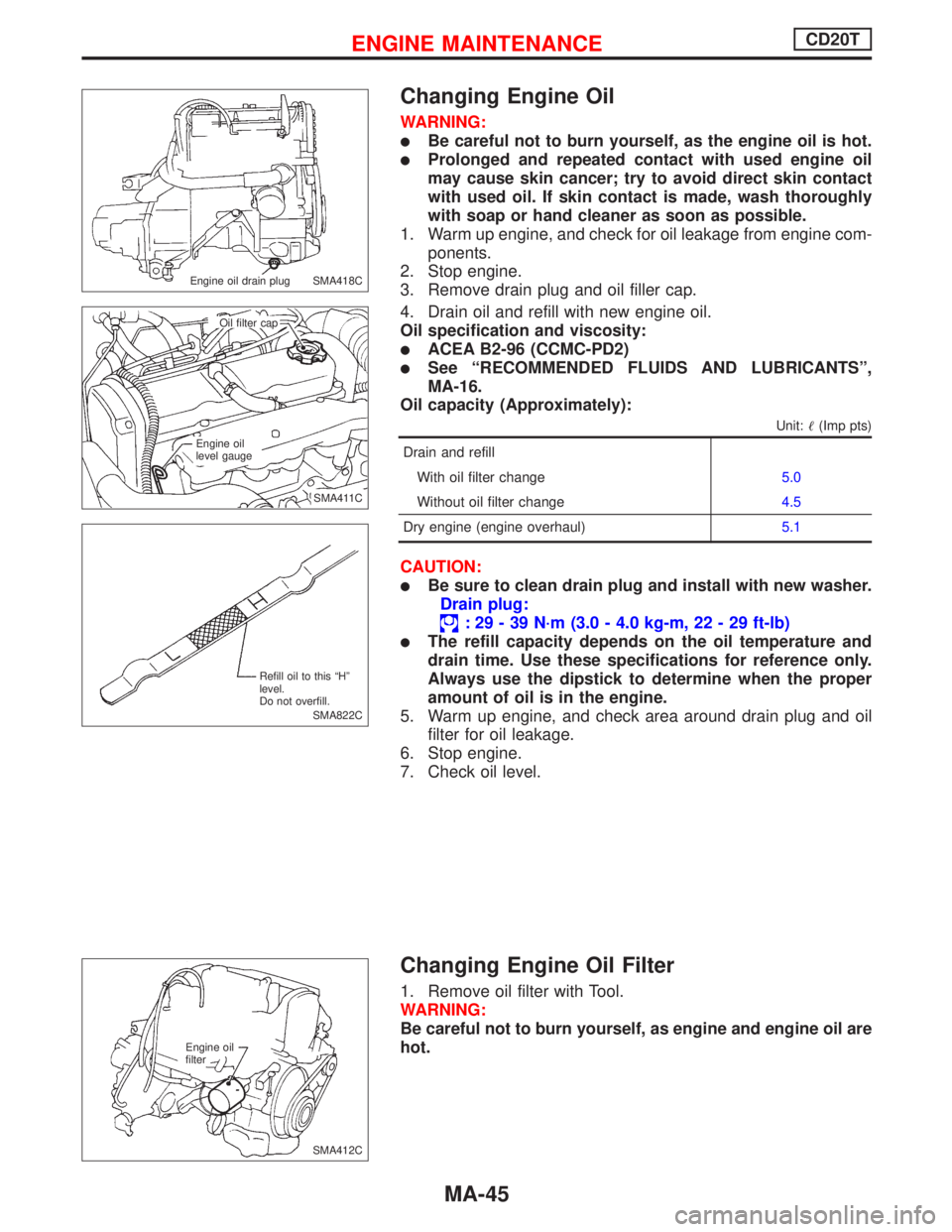
Changing Engine Oil
WARNING:
�Be careful not to burn yourself, as the engine oil is hot.
�Prolonged and repeated contact with used engine oil
may cause skin cancer; try to avoid direct skin contact
with used oil. If skin contact is made, wash thoroughly
with soap or hand cleaner as soon as possible.
1. Warm up engine, and check for oil leakage from engine com-
ponents.
2. Stop engine.
3. Remove drain plug and oil filler cap.
4. Drain oil and refill with new engine oil.
Oil specification and viscosity:
�ACEA B2-96 (CCMC-PD2)
�See“RECOMMENDED FLUIDS AND LUBRICANTS”,
MA-16.
Oil capacity (Approximately):
Unit:�(Imp pts)
Drain and refill
With oil filter change5.0
Without oil filter change4.5
Dry engine (engine overhaul)5.1
CAUTION:
�Be sure to clean drain plug and install with new washer.
Drain plug:
:29-39N·m (3.0 - 4.0 kg-m, 22 - 29 ft-lb)
�The refill capacity depends on the oil temperature and
drain time. Use these specifications for reference only.
Always use the dipstick to determine when the proper
amount of oil is in the engine.
5. Warm up engine, and check area around drain plug and oil
filter for oil leakage.
6. Stop engine.
7. Check oil level.
Changing Engine Oil Filter
1. Remove oil filter with Tool.
WARNING:
Be careful not to burn yourself, as engine and engine oil are
hot.
SMA418C Engine oil drain plug
.SMA411C Oil filter cap
Engine oil
level gauge
SMA822C Refill oil to this“H”
level.
Do not overfill.
SMA412C Engine oil
filter
ENGINE MAINTENANCECD20T
MA-45
Page 2065 of 2267
Checking Exhaust System
Check exhaust pipes, silencers and mountings are attached cor-
rectly and inspect for leaks, cracks, damage, loose connections,
chafing or deterioration.
Checking Clutch Fluid Level and Leaks
If fluid level is very low, check clutch system for leaks.
Checking Clutch System
HYDRAULIC TYPE
Check fluid lines, operating cylinder & damper for leaks, cracks,
damage, loose connections, chafing & deterioration.
MECHANICAL TYPE
Check cable and linkage for incorrect attachment, chafing, wear
and deterioration.
Checking M/T Oil
Check for oil leakage and oil level.
Never start engine while checking oil level.
Filler plug:
:25-34N·m (2.6 - 3.4 kg-m, 19 - 25 ft-lb)
SMA211A
.SMA449C
NMA044
SMA141A
SMA065C
CHASSIS AND BODY MAINTENANCE
MA-48
Page 2066 of 2267
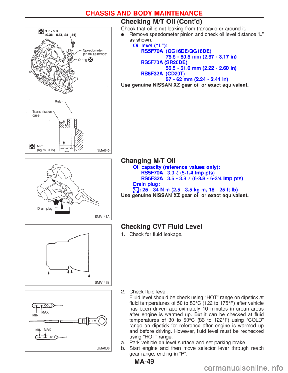
Check that oil is not leaking from transaxle or around it.
�Remove speedometer pinion and check oil level distance“L”
as shown.
Oil level (“L”):
RS5F70A (QG16DE/QG18DE)
75.5 - 80.5 mm (2.97 - 3.17 in)
RS5F70A (SR20DE)
56.5 - 61.0 mm (2.22 - 2.60 in)
RS5F32A (CD20T)
57 - 62 mm (2.24 - 2.44 in)
Use genuine NISSAN XZ gear oil or exact equivalent.
Changing M/T Oil
Oil capacity (reference values only):
RS5F70A 3.0�(5-1/4 Imp pts)
RS5F32A 3.6 - 3.8�(6-3/8 - 6-3/4 Imp pts)
Drain plug:
:25-34N·m (2.5 - 3.5 kg-m, 18 - 25 ft-lb)
Use genuine NISSAN XZ gear oil or exact equivalent.
Checking CVT Fluid Level
1. Check for fluid leakage.
2. Check fluid level.
Fluid level should be check using“HOT”range on dipstick at
fluid temperatures of 50 to 80°C (122 to 176°F) after vehicle
has been driven approximately 10 minutes in urban areas
after engine is warmed up. But it can be checked at fluid
temperatures of 30 to 50°C (86 to 122°F) using“COLD”
range on dipstick for reference after engine is warmed up
and before driving. However, fluid level must be rechecked
using“HOT”range.
a. Park vehicle on level surface and set parking brake.
b. Start engine and then move selector lever through reach
gear range, ending in“P”.
NMA045
3.7 - 5.0
(0.38 - 0.51, 33 - 44)
Speedometer
pinion assembly
O-ring
Ruler
Transmission
case
:N·m
(kg-m, in-lb)
SMA145A Drain plug
SMA146B
UMA036 MAX
MIN
MINMAX
CHASSIS AND BODY MAINTENANCE
Checking M/T Oil (Cont’d)
MA-49
Page 2067 of 2267
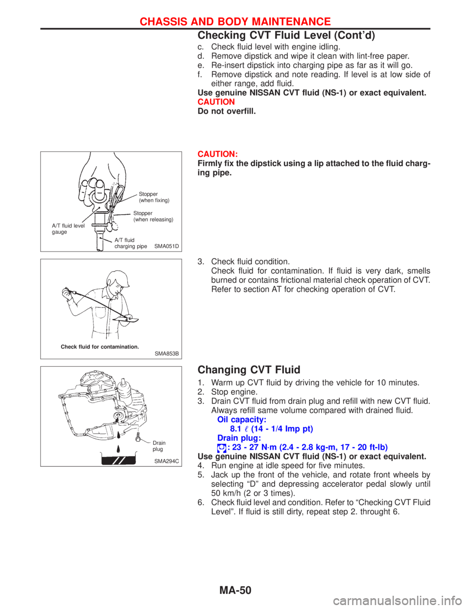
c. Check fluid level with engine idling.
d. Remove dipstick and wipe it clean with lint-free paper.
e. Re-insert dipstick into charging pipe as far as it will go.
f. Remove dipstick and note reading. If level is at low side of
either range, add fluid.
Use genuine NISSAN CVT fluid (NS-1) or exact equivalent.
CAUTION
Do not overfill.
CAUTION:
Firmly fix the dipstick using a lip attached to the fluid charg-
ing pipe.
3. Check fluid condition.
Check fluid for contamination. If fluid is very dark, smells
burned or contains frictional material check operation of CVT.
Refer to section AT for checking operation of CVT.
Changing CVT Fluid
1. Warm up CVT fluid by driving the vehicle for 10 minutes.
2. Stop engine.
3. Drain CVT fluid from drain plug and refill with new CVT fluid.
Always refill same volume compared with drained fluid.
Oil capacity:
8.1�(14 - 1/4 Imp pt)
Drain plug:
:23-27N·m (2.4 - 2.8 kg-m, 17 - 20 ft-lb)
Use genuine NISSAN CVT fluid (NS-1) or exact equivalent.
4. Run engine at idle speed for five minutes.
5. Jack up the front of the vehicle, and rotate front wheels by
selecting“D”and depressing accelerator pedal slowly until
50 km/h (2 or 3 times).
6. Check fluid level and condition. Refer to“Checking CVT Fluid
Level”. If fluid is still dirty, repeat step 2. throught 6.
SMA051D Stopper
(when fixing)
A/T fluid level
gauge
A/T fluid
charging pipeStopper
(when releasing)
SMA853B Check fluid for contamination.
SMA294C Drain
plug
CHASSIS AND BODY MAINTENANCE
Checking CVT Fluid Level (Cont’d)
MA-50
Page 2084 of 2267
NCMT0003
NVH Troubleshooting ChartNCMT0003S01
Use the chart below to help you find the cause of the symptom. The numbers indicate the order of the inspec-
tion. If necessary, repair or replace these parts.
Reference page
Refer to MA section (ªChecking
M/T Oilº, ªCHASSIS AND BODY
MAINTENANCEº).
MT-15, 48
MT-15, 48
MT-15, 48
MT-14, 47
MT-17, 50
MT-17, 50
MT-16, 49
MT-16, 49
MT-16, 49
MT-16, 49
SUSPECTED PARTS
(Possible cause)
(Oil level is low.)
(Wrong oil)
(Oil level is high.)
GASKET (Damaged)
OIL SEAL (Worn or damaged)
O-RING (Worn or damaged)
CONTROL ROD (Worn)
CHECK PLUG RETURN SPRING AND CHECK BALL (Worn or damaged)
SHIFT FORK (Worn)
GEAR (Worn or damaged)
BEARING (Worn or damaged)
BAULK RING (Worn or damaged)
INSERT SPRING, SHIFTING INSERT (Damaged)
SymptomNoise 1 2 3 3
Oil leakage31222
Hard to shift or will not shift 1 1 2 3 3
Jumps out of gear1233
NOISE, VIBRATION AND HARSHNESS (NVH) TROUBLESHOOTING
NVH Troubleshooting Chart
MT-7
Page 2163 of 2267
General Specifications Ð RS5F32A and
RS5F70A
TRANSAXLE
Engine CD20T QG16DE QG18DE SR20DE
Transaxle model RS5F32A RS5F70A
Transaxle model code number 2J624 8E069 7J006 6J016
Number of speeds5
Synchromesh typeWarner
Shift pattern
NMT031
Gear ratio 1st 3.3333 3.3333
2nd 1.9545 1.9545
3rd 1.2857 1.2857
4th 0.9268 0.9268
5th 0.7333 0.7556
Reverse 3.2143 3.2143
Number of teeth Input gear 1st 15 15
2nd 22 22
3rd 28 28
4th 41 41
5th 45 45
Rev. 14 14
Main gear 1st 50 50
2nd 43 43
3rd 36 36
4th 38 38
5th 33 34
Rev. 45 45
Reverse idler gear 31 37
Oil capacity (Reference)(Imp pt) 3.6 - 3.8 (6-3/8 - 6-3/4) 3.0 (5-1/4)
Oil level mm (in)
57 - 62 (2.244 - 2.441)75.5 - 80.5
(2.972 - 3.169)56.5 - 61.0
(2.224 - 2.402)
FINAL GEAR
Engine QG16DE QG18DE/ SR20DE CD20T
Final gear ratio 4.4375 4.1765 3.8888
Number of
teethFinal gear/
Pinion71/16 71/17 70/18
Side gear/
Pinion16/10 14/10 14/10
SERVICE DATA AND SPECIFICATIONS (SDS)
General Specifications Ð RS5F32A and RS5F70A
MT-86
Page 2244 of 2267
STEERING SYSTEM
SECTION
ST
CONTENTS
PRECAUTIONS AND PREPARATION.......................... 2
Precautions ................................................................ 2
Preparation ................................................................ 2
PREPARATION.............................................................. 3
NOISE, VIBRATION AND HARSHNESS (NVH)
TROUBLESHOOTING................................................... 4
NVH Troubleshooting Chart....................................... 4
ON-VEHICLE INSPECTION.......................................... 5
Checking Steering Wheel Play .................................. 5
Checking Neutral Position on Steering Wheel .......... 5
Front Wheel Turning Angle ........................................ 5
Checking Gear Housing Movement .......................... 5
Checking and Adjusting Drive Belts .......................... 6
Checking Fluid Level ................................................. 6
Checking Fluid Leakage ............................................ 6
Bleeding Hydraulic System........................................ 6
Checking Steering Wheel Turning Force .................. 7
Checking Hydraulic System....................................... 8
STEERING WHEEL AND STEERING COLUMN.......... 9
Removal and Installation ......................................... 10
Disassembly and Assembly ...................................... 11
Inspection................................................................. 12POWER STEERING GEAR AND LINKAGE.............. 14
Removal and Installation ......................................... 14
Disassembly............................................................. 17
Inspection................................................................. 17
Assembly ................................................................. 19
SR20DE
POWER STEERING OIL PUMP.................................. 20
CD20T
POWER STEERING OIL PUMP.................................. 21
QG16, 18DE
POWER STEERING OIL PUMP.................................. 22
SR20DE, CD20T, QG16DE, QG18DE
SERVICE DATA AND SPECIFICATIONS (SDS)........ 23
General Specifications ............................................. 23
Inspection and Adjustment ...................................... 23
ST