1999 NISSAN PRIMERA oil level
[x] Cancel search: oil levelPage 36 of 2267
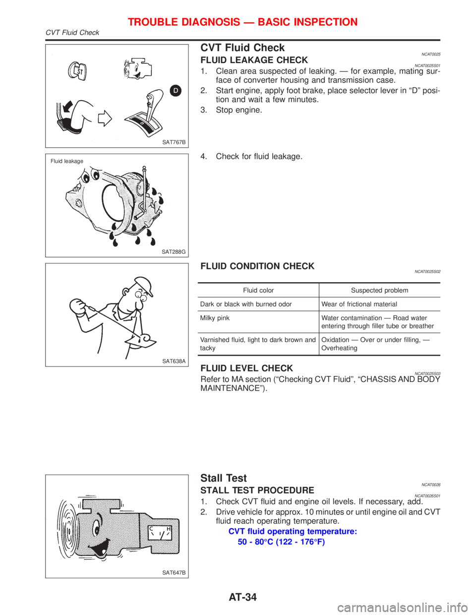
CVT Fluid CheckNCAT0025FLUID LEAKAGE CHECKNCAT0025S011. Clean area suspected of leaking. Ð for example, mating sur-
face of converter housing and transmission case.
2. Start engine, apply foot brake, place selector lever in ªDº posi-
tion and wait a few minutes.
3. Stop engine.
4. Check for fluid leakage.
FLUID CONDITION CHECKNCAT0025S02
Fluid color Suspected problem
Dark or black with burned odor Wear of frictional material
Milky pink Water contamination Ð Road water
entering through filler tube or breather
Varnished fluid, light to dark brown and
tackyOxidation Ð Over or under filling, Ð
Overheating
FLUID LEVEL CHECKNCAT0025S03Refer to MA section (ªChecking CVT Fluidº, ªCHASSIS AND BODY
MAINTENANCEº).
Stall TestNCAT0026STALL TEST PROCEDURENCAT0026S011. Check CVT fluid and engine oil levels. If necessary, add.
2. Drive vehicle for approx. 10 minutes or until engine oil and CVT
fluid reach operating temperature.
CVT fluid operating temperature:
50 - 80ÉC (122 - 176ÉF)
SAT767B
SAT288G Fluid leakage
SAT638A
SAT647B
TROUBLE DIAGNOSIS Ð BASIC INSPECTION
CVT Fluid Check
AT-34
Page 37 of 2267
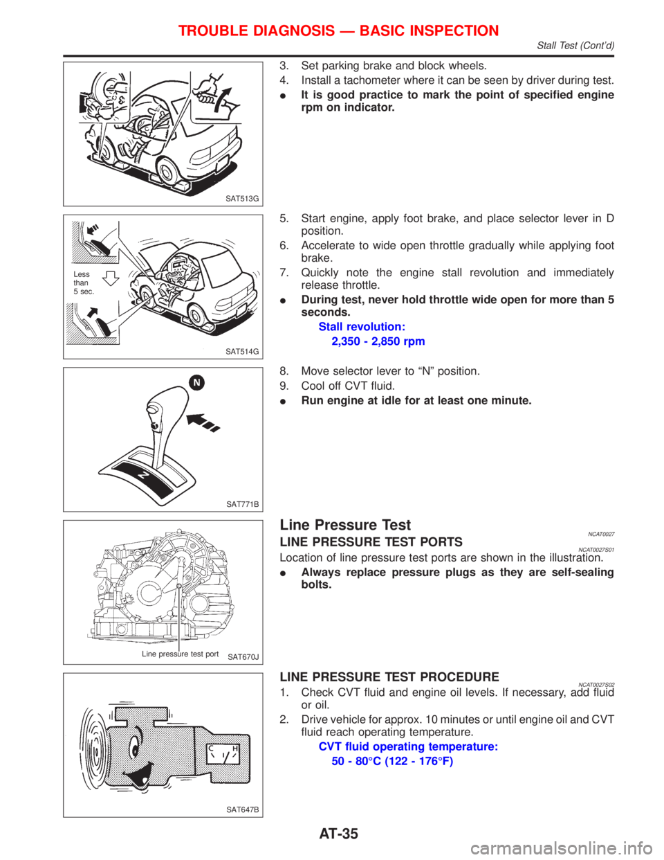
3. Set parking brake and block wheels.
4. Install a tachometer where it can be seen by driver during test.
IIt is good practice to mark the point of specified engine
rpm on indicator.
5. Start engine, apply foot brake, and place selector lever in D
position.
6. Accelerate to wide open throttle gradually while applying foot
brake.
7. Quickly note the engine stall revolution and immediately
release throttle.
IDuring test, never hold throttle wide open for more than 5
seconds.
Stall revolution:
2,350 - 2,850 rpm
8. Move selector lever to ªNº position.
9. Cool off CVT fluid.
IRun engine at idle for at least one minute.
Line Pressure TestNCAT0027LINE PRESSURE TEST PORTSNCAT0027S01Location of line pressure test ports are shown in the illustration.
IAlways replace pressure plugs as they are self-sealing
bolts.
LINE PRESSURE TEST PROCEDURENCAT0027S021. Check CVT fluid and engine oil levels. If necessary, add fluid
or oil.
2. Drive vehicle for approx. 10 minutes or until engine oil and CVT
fluid reach operating temperature.
CVT fluid operating temperature:
50 - 80ÉC (122 - 176ÉF)
SAT513G
SAT514G Less
than
5 sec.
SAT771B
SAT670J Line pressure test port
SAT647B
TROUBLE DIAGNOSIS Ð BASIC INSPECTION
Stall Test (Cont'd)
AT-35
Page 121 of 2267
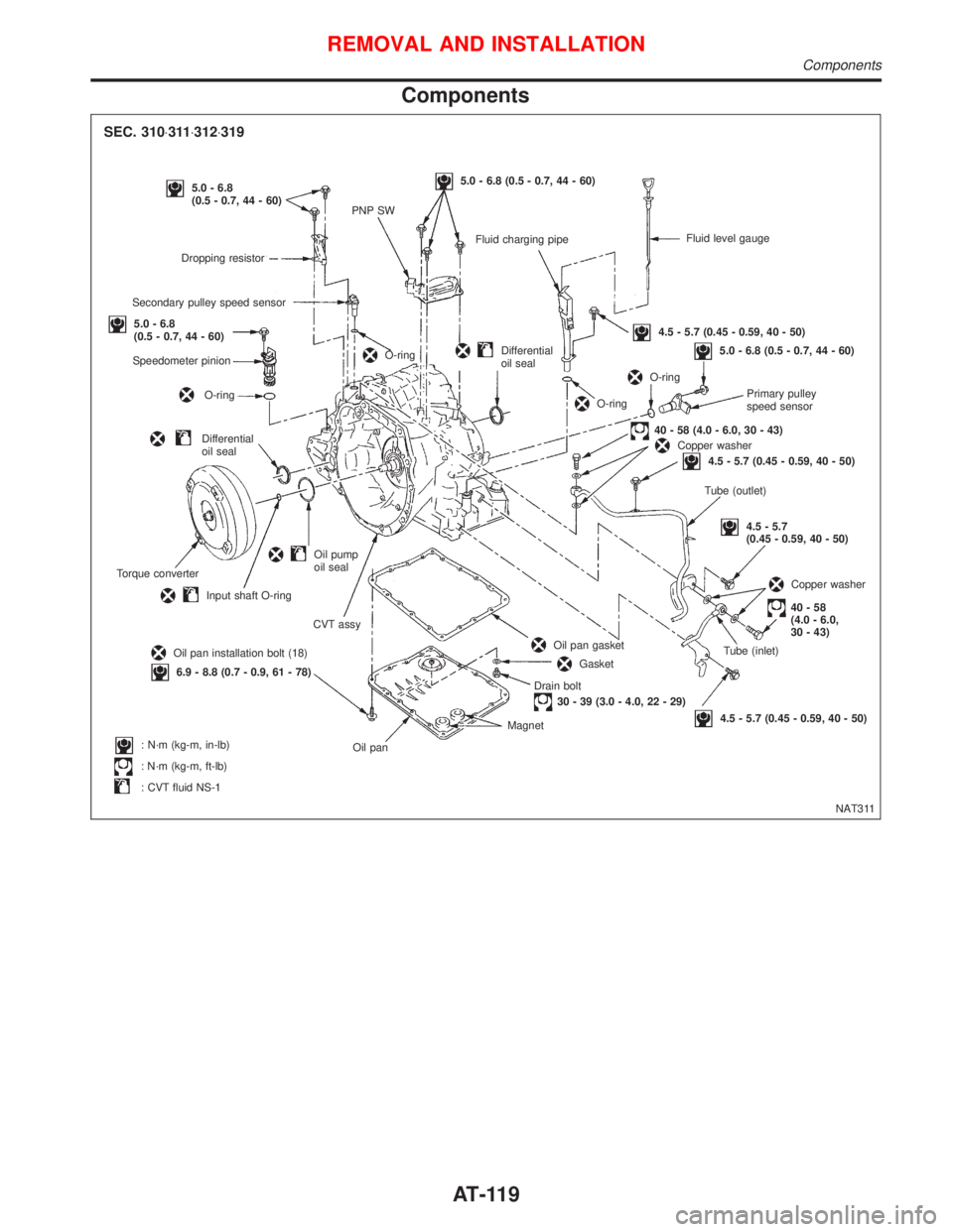
Components
NAT311 Fluid level gauge
Fluid charging pipe
5.0 - 6.8 (0.5 - 0.7, 44 - 60)
PNP SW5.0 - 6.8
(0.5 - 0.7, 44 - 60)
Dropping resistor
Secondary pulley speed sensor
5.0 - 6.8
(0.5 - 0.7, 44 - 60)
Speedometer pinion
O-ring
O-ringDifferential
oil seal
Torque converter
Input shaft O-ring
Oil pump
oil seal
CVT assy
Oil pan installation bolt (18)
6.9 - 8.8 (0.7 - 0.9, 61 - 78)
: N´m (kg-m, in-lb)
: N´m (kg-m, ft-lb)
: CVT fluid NS-1Oil panMagnetDrain bolt
30 - 39 (3.0 - 4.0, 22 - 29)
Gasket
Oil pan gasket
4.5 - 5.7 (0.45 - 0.59, 40 - 50)Tube (inlet)
40-58
(4.0 - 6.0,
30 - 43)
Copper washer
4.5 - 5.7
(0.45 - 0.59, 40 - 50) Tube (outlet)
4.5 - 5.7 (0.45 - 0.59, 40 - 50)Copper washer40 - 58 (4.0 - 6.0, 30 - 43)Primary pulley
speed sensor
5.0 - 6.8 (0.5 - 0.7, 44 - 60)
O-ring
O-ring
4.5 - 5.7 (0.45 - 0.59, 40 - 50)
Differential
oil seal
SEC. 310×311×312×319
REMOVAL AND INSTALLATION
Components
AT-119
Page 129 of 2267
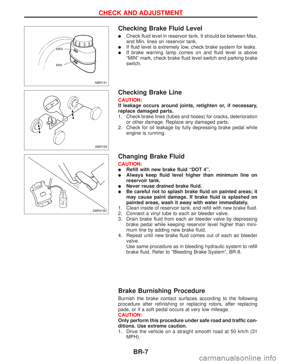
Checking Brake Fluid Level
lCheck fluid level in reservoir tank. It should be between Max.
and Min. lines on reservoir tank.
lIf fluid level is extremely low, check brake system for leaks.
lIf brake warning lamp comes on and fluid level is above
ªMINº mark, check brake fluid level switch and parking brake
switch.
Checking Brake Line
CAUTION:
If leakage occurs around joints, retighten or, if necessary,
replace damaged parts.
1. Check brake lines (tubes and hoses) for cracks, deterioration
or other damage. Replace any damaged parts.
2. Check for oil leakage by fully depressing brake pedal while
engine is running.
Changing Brake Fluid
CAUTION:
lRefill with new brake fluid ªDOT 4º.
lAlways keep fluid level higher than minimum line on
reservoir tank.
lNever reuse drained brake fluid.
lBe careful not to splash brake fluid on painted areas; it
may cause paint damage. If brake fluid is splashed on
painted areas, wash it away with water immediately.
1. Clean inside of reservoir tank, and refill with new brake fluid.
2. Connect a vinyl tube to each air bleeder valve.
3. Drain brake fluid from each air bleeder valve by depressing
brake pedal while keeping reservoir level higher than mini-
mum line by adding new brake fluid.
4. Repeat until new brake fluid comes out of each air bleeder
valve.
Use same procedure as in bleeding hydraulic system to refill
brake fluid. Refer to ªBleeding Brake Systemº, BR-8.
Brake Burnishing Procedure
Burnish the brake contact surfaces according to the following
procedure after refinishing or replacing rotors, after replacing
pads, or if a soft pedal occurs at very low mileage.
CAUTION:
Only perform this procedure under safe road and traffic con-
ditions. Use extreme caution.
1. Drive the vehicle on a straight smooth road at 50 km/h (31
MPH).
NBR141 MAX.
MIN.
ABR159
SBR419C
CHECK AND ADJUSTMENT
BR-7
Page 137 of 2267
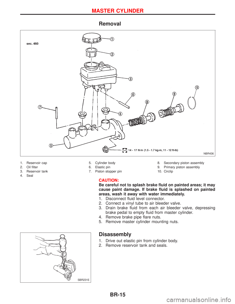
Removal
1. Reservoir cap
2. Oil filter
3. Reservoir tank
4. Seal5. Cylinder body
6. Elastic pin
7. Piston stopper pin8. Secondary piston assembly
9. Primary piston assembly
10. Circlip
CAUTION:
Be careful not to splash brake fluid on painted areas; it may
cause paint damage. If brake fluid is splashed on painted
areas, wash it away with water immediately.
1. Disconnect fluid level connector.
2. Connect a vinyl tube to air bleeder valve.
3. Drain brake fluid from each air bleeder valve, depressing
brake pedal to empty fluid from master cylinder.
4. Remove brake pipe flare nuts.
5. Remove master cylinder mounting nuts.
Disassembly
1. Drive out elastic pin from cylinder body.
2. Remove reservoir tank and seals.
NBR436
SBR231E
MASTER CYLINDER
BR-15
Page 150 of 2267
CAUTION:
Do not use any sharp tools or cleaning agents which con-
tains mineral oil. Damage to the installation can occur.
10. Clean the cylinder body and guide grooves in the torque
member.
11. Check the dust cover and guide sleeves for damage.
12. Measure the amount of wear on the brake pad
Standard pad thickness:
11 mm (0.43 in)
Pad wear limit:
2.0 mm (0.079 in)
14. Press the piston fully back with a suitable tool.
CAUTION:
Carefully monitor brake fluid level to avoid brake fluid from
returning to the reservoir when pushing back the piston.
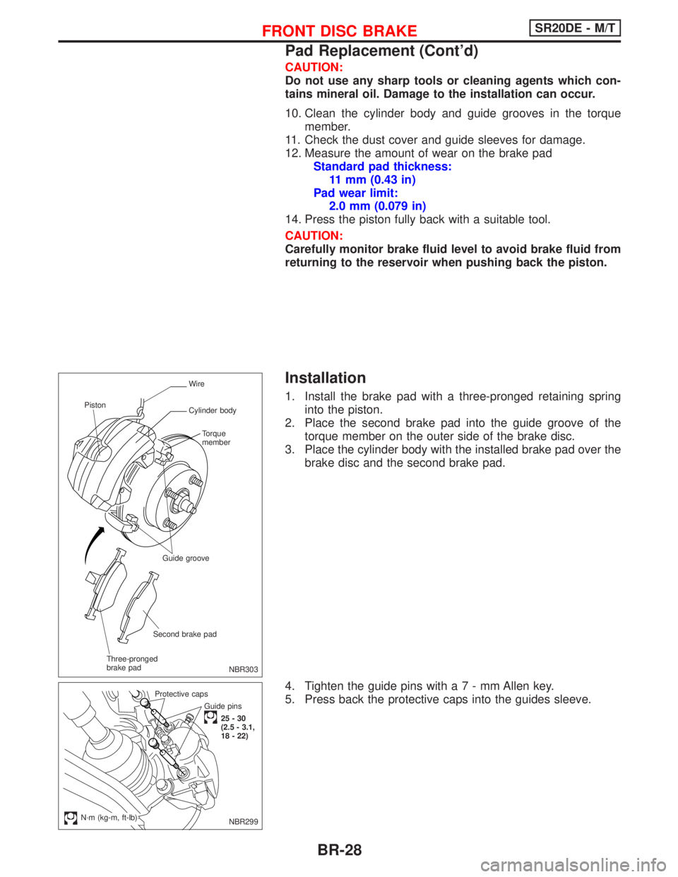
Installation
1. Install the brake pad with a three-pronged retaining spring
into the piston.
2. Place the second brake pad into the guide groove of the
torque member on the outer side of the brake disc.
3. Place the cylinder body with the installed brake pad over the
brake disc and the second brake pad.
4. Tighten the guide pins witha7-mmAllen key.
5. Press back the protective caps into the guides sleeve.
NBR303
Wire
Cylinder body
Torque
member
Guide groove
Second brake pad
Three-pronged
brake pad Piston
Guide pins
25-30
(2.5 - 3.1,
18 - 22) Protective caps
.N´m (kg-m, ft-lb)NBR299
FRONT DISC BRAKESR20DE - M/T
Pad Replacement (Cont'd)
BR-28
Page 381 of 2267
Cooling Fan (Overheat)
SYSTEM DESCRIPTION
Vehicle speed sensorEVehicle speed
ECM
ECooling
fan
relay(s)Engine coolant temperature sensorEEngine coolant temperature
Air conditioner switch
EAir conditioner ªONº signal
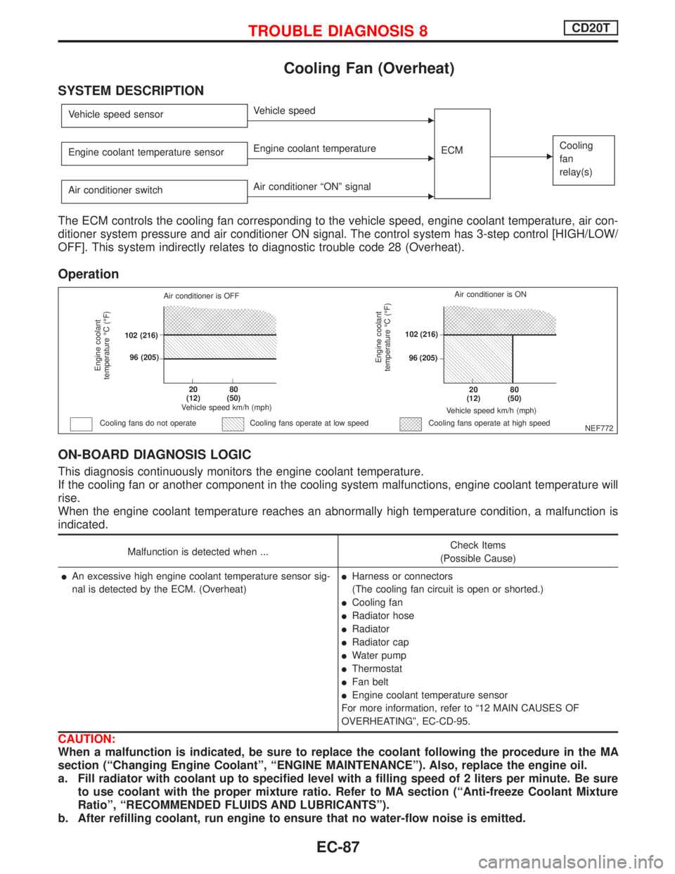
The ECM controls the cooling fan corresponding to the vehicle speed, engine coolant temperature, air con-
ditioner system pressure and air conditioner ON signal. The control system has 3-step control [HIGH/LOW/
OFF]. This system indirectly relates to diagnostic trouble code 28 (Overheat).
Operation
ON-BOARD DIAGNOSIS LOGIC
This diagnosis continuously monitors the engine coolant temperature.
If the cooling fan or another component in the cooling system malfunctions, engine coolant temperature will
rise.
When the engine coolant temperature reaches an abnormally high temperature condition, a malfunction is
indicated.
Malfunction is detected when ...Check Items
(Possible Cause)
lAn excessive high engine coolant temperature sensor sig-
nal is detected by the ECM. (Overheat)lHarness or connectors
(The cooling fan circuit is open or shorted.)
lCooling fan
lRadiator hose
lRadiator
lRadiator cap
lWater pump
lThermostat
lFan belt
lEngine coolant temperature sensor
For more information, refer to ª12 MAIN CAUSES OF
OVERHEATINGº, EC-CD-95.
CAUTION:
When a malfunction is indicated, be sure to replace the coolant following the procedure in the MA
section (ªChanging Engine Coolantº, ªENGINE MAINTENANCEº). Also, replace the engine oil.
a. Fill radiator with coolant up to specified level with a filling speed of 2 liters per minute. Be sure
to use coolant with the proper mixture ratio. Refer to MA section (ªAnti-freeze Coolant Mixture
Ratioº, ªRECOMMENDED FLUIDS AND LUBRICANTSº).
b. After refilling coolant, run engine to ensure that no water-flow noise is emitted.
NEF772
Engine coolant
temperature ÉC (ÉF)
Air conditioner is OFF
.102 (216)
.96 (205)
.20
(12).80
(50)
Vehicle speed km/h (mph)
Cooling fans do not operateCooling fans operate at high speed
Engine coolant
temperature ÉC (ÉF)
Vehicle speed km/h (mph)
.20
(12).80
(50)
.102 (216)
.96 (205)Air conditioner is ON
Cooling fans operate at low speed
TROUBLE DIAGNOSIS 8CD20T
EC-87
Page 527 of 2267
SYMPTOM
Reference
page
HARD/NO START/RESTART (EXCP. HA)
ENGINE STALL
HESITATION/SURGING/FLAT SPOT
SPARK KNOCK/DETONATION
LACK OF POWER/POOR ACCELERATION
HIGH IDLE/LOW IDLE
ROUGH IDLE/HUNTING
IDLING VIBRATION
SLOW/NO RETURN TO IDLE
OVERHEATS/WATER TEMPERATURE HIGH
EXCESSIVE FUEL CONSUMPTION
EXCESSIVE OIL CONSUMPTION
BATTERY DEAD (UNDER CHARGE)
Warranty symptom code AA AB AC AD AE AF AG AH AJ AK AL AM HA
Engine Cylinder head
55555 55 5
EM section Cylinder head gasket 4 3
Cylinder block
66666 66 64 Piston
Piston ring
Connecting rod
Bearing
Crankshaft
Valve
mecha-
nismTiming chain
55555 55 5 EMsection Camshaft
Intake valve
3
Exhaust valve
Exhaust Exhaust manifold/Tube/Muffler/
Gasket
55555 55 5 FEsection
Three way catalyst
Lubrica-
tionOil pan/Oil strainer/Oil pump/Oil
filter/Oil gallery
55555 55 5MA, EM and
LC sections
Oil level (Low)/Filthy oil
LC section Cooling Radiator/Hose/Radiator filler cap
55555 55 45 Thermostat 5
Water pump
Water gallery
Cooling fan 5 EC-QG-289
Coolant level (low)/
Contaminated coolantMA section
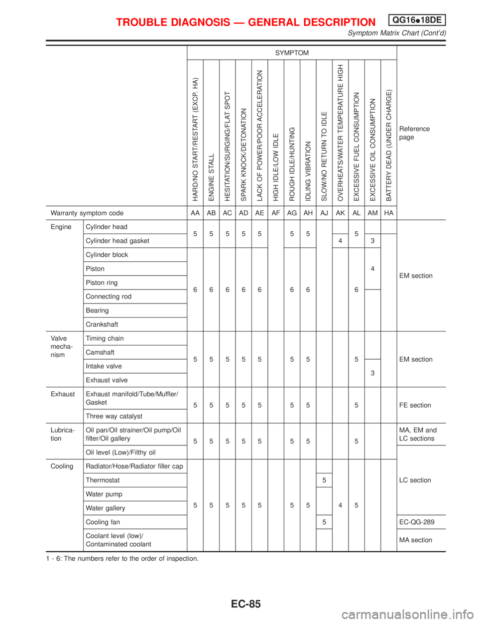
1 - 6: The numbers refer to the order of inspection.
TROUBLE DIAGNOSIS Ð GENERAL DESCRIPTIONQG16I18DE
Symptom Matrix Chart (Cont'd)
EC-85