Page 187 of 2267
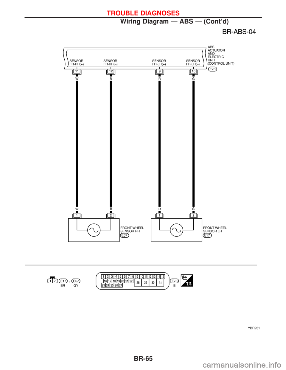
YBR231
TROUBLE DIAGNOSES
Wiring Diagram Ð ABS Ð (Cont'd)
BR-65
Page 188 of 2267
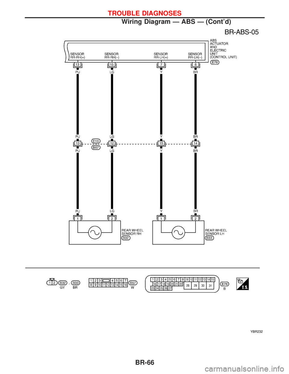
YBR232
TROUBLE DIAGNOSES
Wiring Diagram Ð ABS Ð (Cont'd)
BR-66
Page 209 of 2267
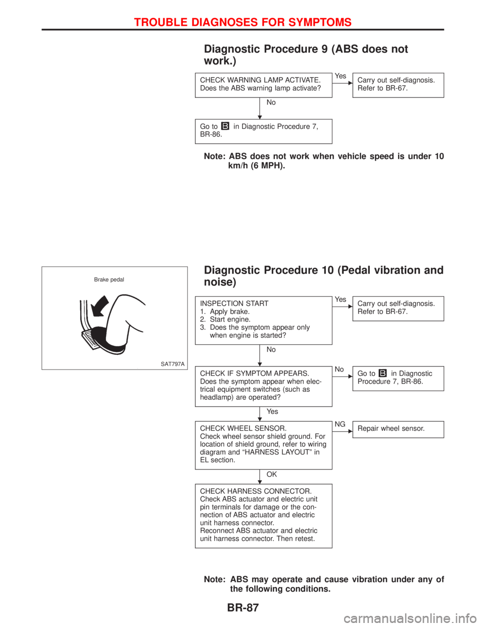
Diagnostic Procedure 9 (ABS does not
work.)
CHECK WARNING LAMP ACTIVATE.
Does the ABS warning lamp activate?
No
EYe s
Carry out self-diagnosis.
Refer to BR-67.
Go toin Diagnostic Procedure 7,
BR-86.
Note: ABS does not work when vehicle speed is under 10
km/h (6 MPH).
Diagnostic Procedure 10 (Pedal vibration and
noise)
INSPECTION START
1. Apply brake.
2. Start engine.
3. Does the symptom appear only
when engine is started?
No
EYe s
Carry out self-diagnosis.
Refer to BR-67.
CHECK IF SYMPTOM APPEARS.
Does the symptom appear when elec-
trical equipment switches (such as
headlamp) are operated?
Ye s
ENo
Go toin Diagnostic
Procedure 7, BR-86.
CHECK WHEEL SENSOR.
Check wheel sensor shield ground. For
location of shield ground, refer to wiring
diagram and ªHARNESS LAYOUTº in
EL section.
OK
ENG
Repair wheel sensor.
CHECK HARNESS CONNECTOR.
Check ABS actuator and electric unit
pin terminals for damage or the con-
nection of ABS actuator and electric
unit harness connector.
Reconnect ABS actuator and electric
unit harness connector. Then retest.
Note: ABS may operate and cause vibration under any of
the following conditions.
SAT797A Brake pedal
H
H
H
H
TROUBLE DIAGNOSES FOR SYMPTOMS
BR-87
Page 216 of 2267
Service Notice
lWhen removing or installing various parts, place a cloth or padding onto the vehicle body to prevent
scratches.
lHandle trim, molding, instruments, grille, etc. carefully during removing or installing. Be careful not to soil
or damage them.
lApply sealing compound where necessary when installing parts.
lWhen applying sealing compound, be careful that the sealing compound does not protrude from parts.
lWhen replacing any metal parts (for example body outer panel, members, etc.), be sure to take rust
prevention measures.
Supplemental Restraint System (SRS) ªAIR
BAGº and ªSEAT BELT PRE-TENSIONERº
The Supplemental Restraint System ªAir Bagº and ªSeat Belt Pre-tensionerº, used along with a seat belt,
helps to reduce the risk or severity of injury to the driver and front passenger in a frontal collision. The
Supplemental Restraint System consists of air bag modules (located in the center of the steering wheel and
on the instrument panel on the passenger side), seat belt pre-tensioners, a diagnosis sensor unit, warning
lamp, wiring harness and spiral cable. Information necessary to service the system safely is included in the
RS sectionof the Service Manual.
If the vehicle is equipped with side air bag as the Supplemental Restraint System, the side air bag used along
with the seat belt helps to reduce the risk or severity of injury to the driver and front passenger in a side
collision. The side air bag consists of air bag modules (located in the outer side of front seats), satellite
sensor, diagnosis sensor unit (which is one of components of air bags for a frontal collision), wiring harness,
warning lamp (which is one of components of air bags for a frontal collision).
WARNING:
lTo avoid rendering the SRS inoperative (which could increase the risk of personal injury or death
in the event of a collision which would result in air bag inflation) all maintenance must be per-
formed by an authorized NISSAN dealer.
lImproper maintenance, including incorrect removal and installation of the SRS, can lead to per-
sonal injury caused by unintentional activation of the system.
lDo not use electrical test equipment on any circuit related to the SRS unless instructed to do so
in this Service Manual. SRS wiring harnesses are covered with yellow insulation (either just
before the harness connectors or for the complete harness) for easy identification.
PRECAUTIONS
BT-2
Page 254 of 2267
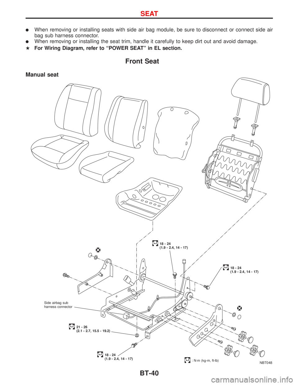
lWhen removing or installing seats with side air bag module, be sure to disconnect or connect side air
bag sub harness connector.
lWhen removing or installing the seat trim, handle it carefully to keep dirt out and avoid damage.
HFor Wiring Diagram, refer to ªPOWER SEATº in EL section.
Front Seat
NBT048
18-24
(1.9 - 2.4, 14 - 17)
18-24
(1.9 - 2.4, 14 - 17)
18-24
(1.9 - 2.4, 14 - 17)
: N´m (kg-m, ft-lb)
21-26
(2.1 - 2.7, 15.5 - 19.2)
Manual seat
Side airbag sub
harness connector
SEAT
BT-40
Page 256 of 2267
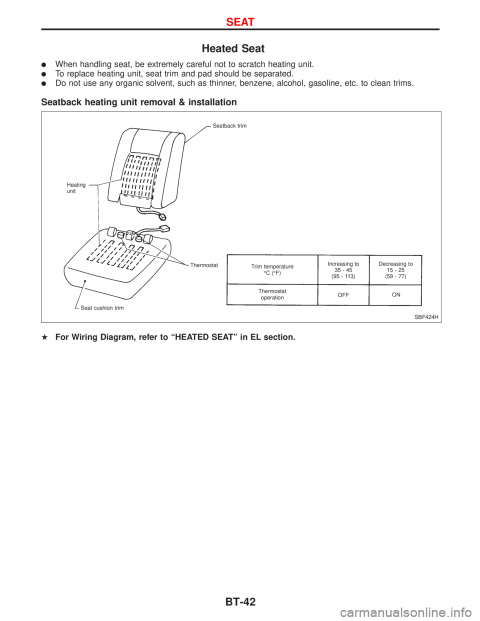
Heated Seat
lWhen handling seat, be extremely careful not to scratch heating unit.
lTo replace heating unit, seat trim and pad should be separated.
lDo not use any organic solvent, such as thinner, benzene, alcohol, gasoline, etc. to clean trims.
Seatback heating unit removal & installation
HFor Wiring Diagram, refer to ªHEATED SEATº in EL section.
SBF424H Seatback trim
Heating
unit
Thermostat
Seat cushion trimTrim temperature
ÉC (ÉF)
Thermostat
operationIncreasing to
35-45
(95 - 113)
OFFDecreasing to
15-25
(59 - 77)
ON
SEAT
BT-42
Page 262 of 2267
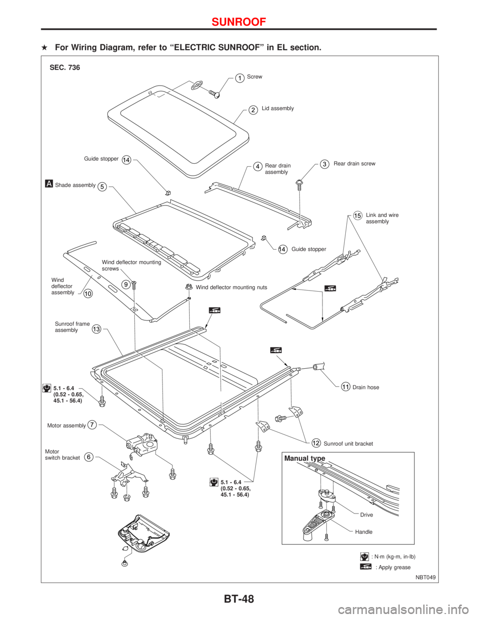
HFor Wiring Diagram, refer to ªELECTRIC SUNROOFº in EL section.
NBT049
SEC. 736
Rear drain
assemblyRear drain screw
Link and wire
assembly
Guide stopper
Wind deflector mounting nuts
Drain hose
Sunroof unit bracket
5.1 - 6.4
(0.52 - 0.65,
45.1 - 56.4) Motor
switch bracketMotor assembly
5.1 - 6.4
(0.52 - 0.65,
45.1 - 56.4)Sunroof frame
assembly Wind
deflector
assemblyWind deflector mounting
screws
Shade assemblyGuide stopperScrew
: N´m (kg-m, in-lb) Lid assembly
Manual type
Drive
Handle
: Apply grease
SUNROOF
BT-48
Page 272 of 2267
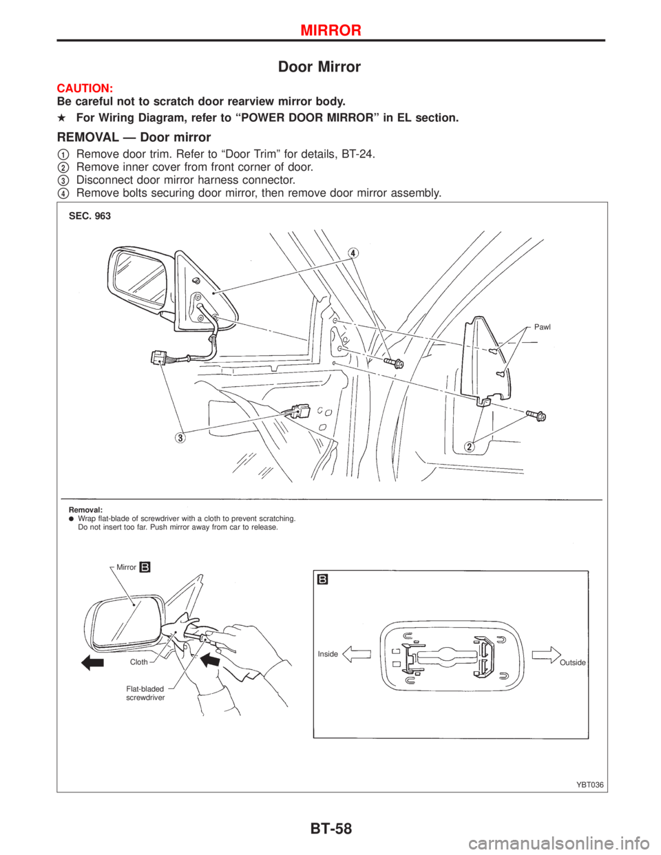
Door Mirror
CAUTION:
Be careful not to scratch door rearview mirror body.
HFor Wiring Diagram, refer to ªPOWER DOOR MIRRORº in EL section.
REMOVAL Ð Door mirror
p1Remove door trim. Refer to ªDoor Trimº for details, BT-24.
p2Remove inner cover from front corner of door.
p3Disconnect door mirror harness connector.
p4Remove bolts securing door mirror, then remove door mirror assembly.
YBT036
SEC. 963
Pawl
Removal:
lWrap flat-blade of screwdriver with a cloth to prevent scratching.
Do not insert too far. Push mirror away from car to release.
Mirror
Cloth
Flat-bladed
screwdriverInside
Outside
MIRROR
BT-58