Page 547 of 2267
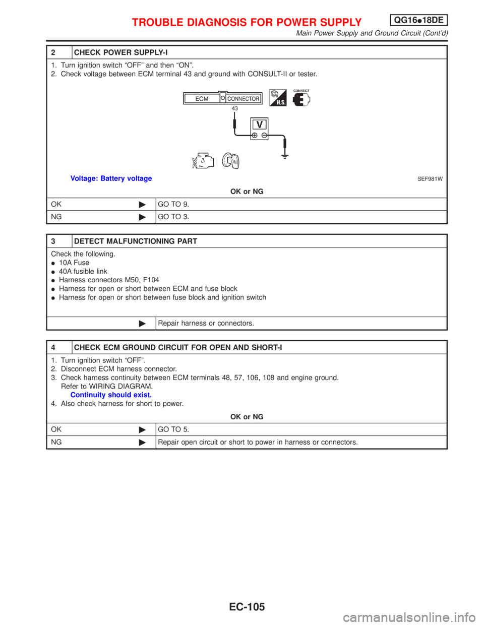
2 CHECK POWER SUPPLY-I
1. Turn ignition switch ªOFFº and then ªONº.
2. Check voltage between ECM terminal 43 and ground with CONSULT-II or tester.
SEF981WVoltage: Battery voltage
OK or NG
OK©GO TO 9.
NG©GO TO 3.
3 DETECT MALFUNCTIONING PART
Check the following.
I10A Fuse
I40A fusible link
IHarness connectors M50, F104
IHarness for open or short between ECM and fuse block
IHarness for open or short between fuse block and ignition switch
©Repair harness or connectors.
4 CHECK ECM GROUND CIRCUIT FOR OPEN AND SHORT-I
1. Turn ignition switch ªOFFº.
2. Disconnect ECM harness connector.
3. Check harness continuity between ECM terminals 48, 57, 106, 108 and engine ground.
Refer to WIRING DIAGRAM.
Continuity should exist.
4. Also check harness for short to power.
OK or NG
OK©GO TO 5.
NG©Repair open circuit or short to power in harness or connectors.
TROUBLE DIAGNOSIS FOR POWER SUPPLYQG16I18DE
Main Power Supply and Ground Circuit (Cont'd)
EC-105
Page 550 of 2267
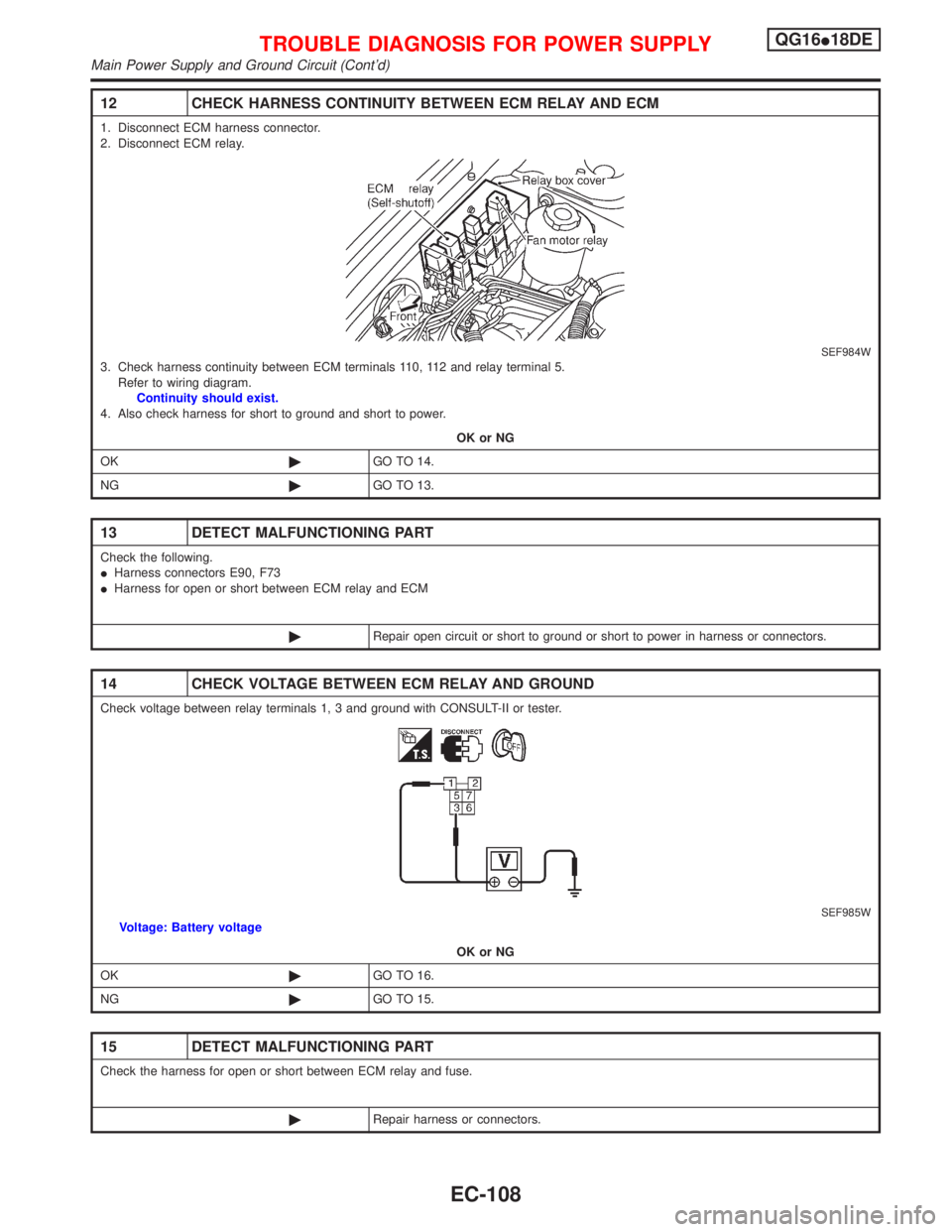
12 CHECK HARNESS CONTINUITY BETWEEN ECM RELAY AND ECM
1. Disconnect ECM harness connector.
2. Disconnect ECM relay.
SEF984W3. Check harness continuity between ECM terminals 110, 112 and relay terminal 5.
Refer to wiring diagram.
Continuity should exist.
4. Also check harness for short to ground and short to power.
OK or NG
OK©GO TO 14.
NG©GO TO 13.
13 DETECT MALFUNCTIONING PART
Check the following.
IHarness connectors E90, F73
IHarness for open or short between ECM relay and ECM
©Repair open circuit or short to ground or short to power in harness or connectors.
14 CHECK VOLTAGE BETWEEN ECM RELAY AND GROUND
Check voltage between relay terminals 1, 3 and ground with CONSULT-II or tester.
SEF985WVoltage: Battery voltage
OK or NG
OK©GO TO 16.
NG©GO TO 15.
15 DETECT MALFUNCTIONING PART
Check the harness for open or short between ECM relay and fuse.
©Repair harness or connectors.
TROUBLE DIAGNOSIS FOR POWER SUPPLYQG16I18DE
Main Power Supply and Ground Circuit (Cont'd)
EC-108
Page 551 of 2267
16 CHECK ECM RELAY
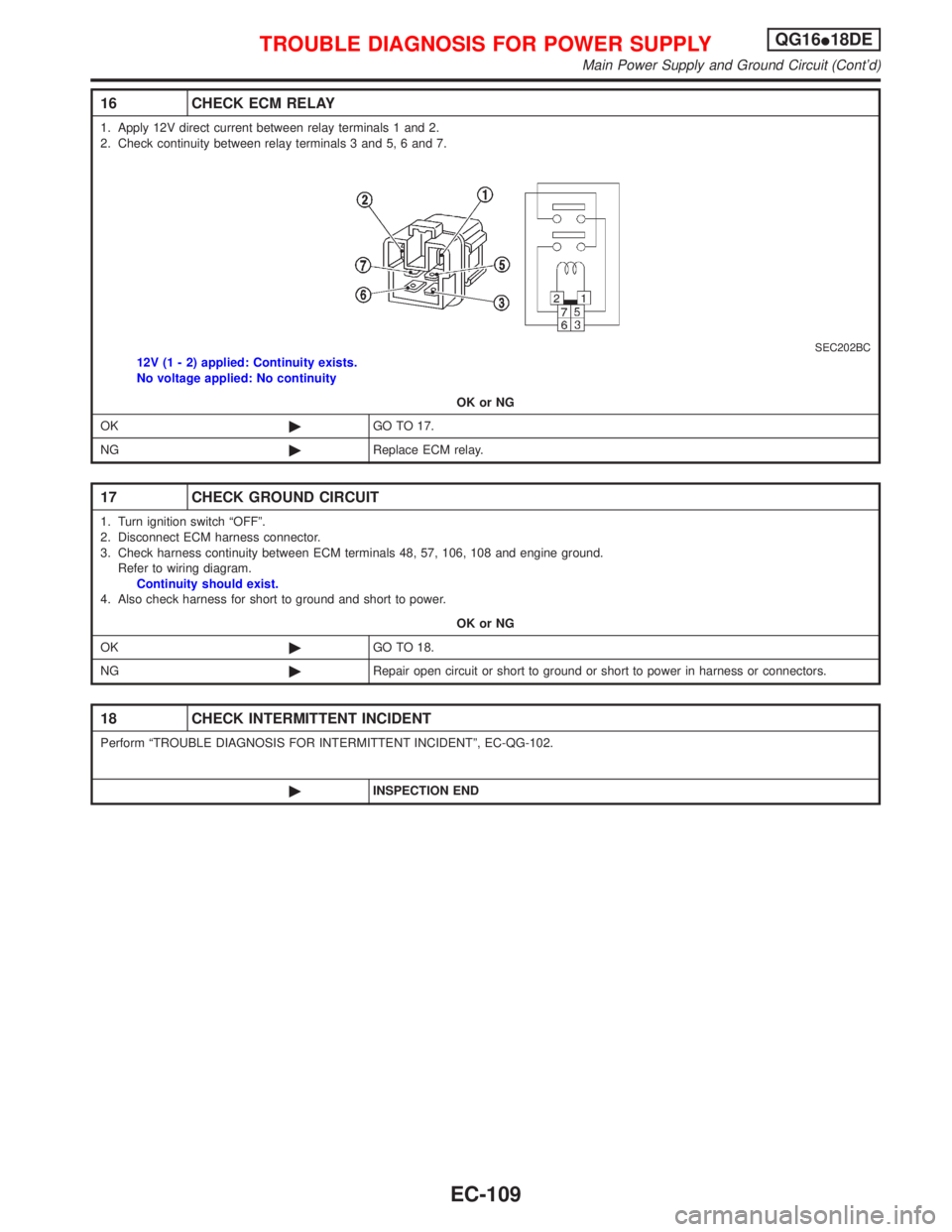
1. Apply 12V direct current between relay terminals 1 and 2.
2. Check continuity between relay terminals 3 and 5, 6 and 7.
SEC202BC12V (1 - 2) applied: Continuity exists.
No voltage applied: No continuity
OK or NG
OK©GO TO 17.
NG©Replace ECM relay.
17 CHECK GROUND CIRCUIT
1. Turn ignition switch ªOFFº.
2. Disconnect ECM harness connector.
3. Check harness continuity between ECM terminals 48, 57, 106, 108 and engine ground.
Refer to wiring diagram.
Continuity should exist.
4. Also check harness for short to ground and short to power.
OK or NG
OK©GO TO 18.
NG©Repair open circuit or short to ground or short to power in harness or connectors.
18 CHECK INTERMITTENT INCIDENT
Perform ªTROUBLE DIAGNOSIS FOR INTERMITTENT INCIDENTº, EC-QG-102.
©INSPECTION END
TROUBLE DIAGNOSIS FOR POWER SUPPLYQG16I18DE
Main Power Supply and Ground Circuit (Cont'd)
EC-109
Page 554 of 2267
Wiring DiagramNCEC0056
YEC063A
DTC P0100 MASS AIR FLOW SENSOR (MAFS)QG16I18DE
Wiring Diagram
EC-112
Page 556 of 2267
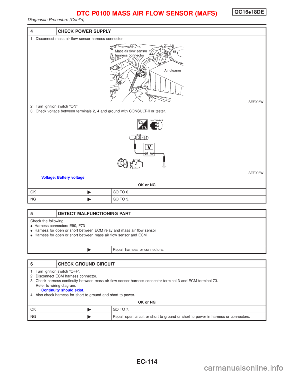
4 CHECK POWER SUPPLY
1. Disconnect mass air flow sensor harness connector.
SEF995W2. Turn ignition switch ªONº.
3. Check voltage between terminals 2, 4 and ground with CONSULT-II or tester.
SEF996WVoltage: Battery voltage
OK or NG
OK©GO TO 6.
NG©GO TO 5.
5 DETECT MALFUNCTIONING PART
Check the following.
IHarness connectors E90, F73
IHarness for open or short between ECM relay and mass air flow sensor
IHarness for open or short between mass air flow sensor and ECM
©Repair harness or connectors.
6 CHECK GROUND CIRCUIT
1. Turn ignition switch ªOFFº.
2. Disconnect ECM harness connector.
3. Check harness continuity between mass air flow sensor harness connector terminal 3 and ECM terminal 73.
Refer to wiring diagram.
Continuity should exist.
4. Also check harness for short to ground and short to power.
OK or NG
OK©GO TO 7.
NG©Repair open circuit or short to ground or short to power in harness or connectors.
DTC P0100 MASS AIR FLOW SENSOR (MAFS)QG16I18DE
Diagnostic Procedure (Cont'd)
EC-114
Page 557 of 2267
7 CHECK INPUT SIGNAL CIRCUIT
1. Check harness continuity between mass air flow sensor harness connector terminal 5 and ECM terminal 61.
Refer to wiring diagram.
Continuity should exist.
2. Also check harness for short to ground and short to power.
OK or NG
OK©GO TO 8.
NG©Repair open circuit or short to ground or short to power in harness or connectors.
8 CHECK MASS AIR FLOW SENSOR
Refer to ªComponent Inspectionº, EC-QG-115.
OK or NG
OK©GO TO 9.
NG©Replace mass air flow sensor.
9 CHECK INTERMITTENT INCIDENT
Perform ªTROUBLE DIAGNOSIS FOR INTERMITTENT INCIDENTº, EC-QG-102.
©INSPECTION END
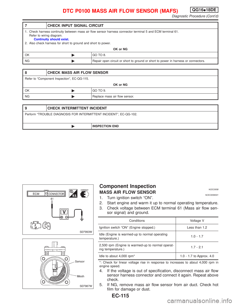
Component InspectionNCEC0058MASS AIR FLOW SENSORNCEC0058S011. Turn ignition switch ªONº.
2. Start engine and warm it up to normal operating temperature.
3. Check voltage between ECM terminal 61 (Mass air flow sen-
sor signal) and ground.
Conditions Voltage V
Ignition switch ªONº (Engine stopped.) Less than 1.2
Idle (Engine is warmed-up to normal operating
temperature.)1.0 - 1.7
2,500 rpm (Engine is warmed-up to normal operat-
ing temperature.)1.7 - 2.1
Idle to about 4,000 rpm* 1.0 - 1.7 to Approx. 4.0
*: Check for linear voltage rise in response to increases to about 4,000 rpm in
engine speed.
4. If the voltage is out of specification, disconnect mass air flow
sensor harness connector and connect it again. Repeat above
check.
5. If NG, remove mass air flow sensor from air duct. Check hot
film for damage or dust.
SEF993W
SEF987W
DTC P0100 MASS AIR FLOW SENSOR (MAFS)QG16I18DE
Diagnostic Procedure (Cont'd)
EC-115
Page 559 of 2267
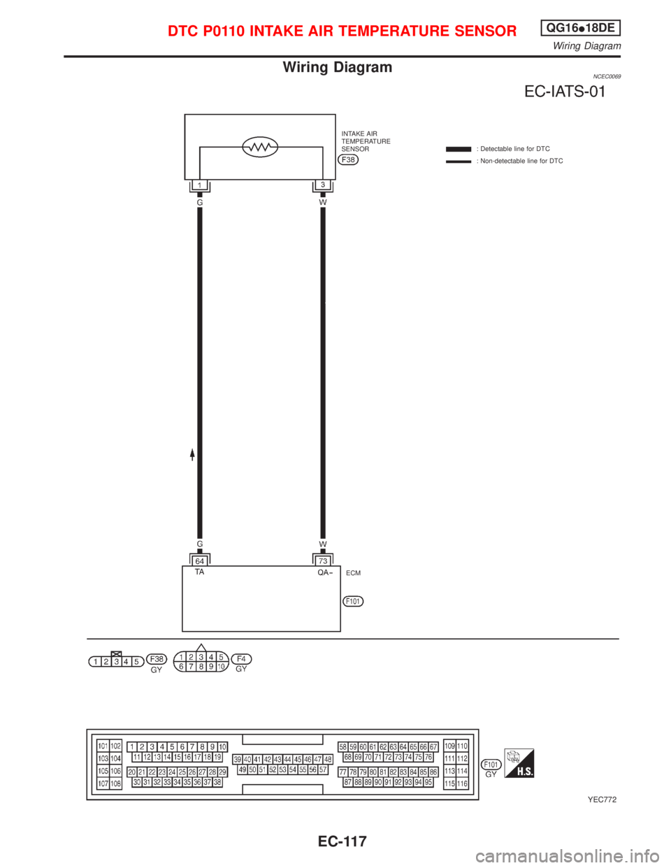
Wiring DiagramNCEC0069
YEC772
INTAKE AIR
TEMPERATURE
SENSOR: Detectable line for DTC
: Non-detectable line for DTC
ECM
DTC P0110 INTAKE AIR TEMPERATURE SENSORQG16I18DE
Wiring Diagram
EC-117
Page 560 of 2267
Diagnostic Procedure
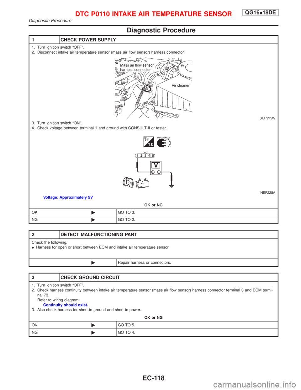
1 CHECK POWER SUPPLY
1. Turn ignition switch ªOFFº.
2. Disconnect intake air temperature sensor (mass air flow sensor) harness connector.
SEF995W3. Turn ignition switch ªONº.
4. Check voltage between terminal 1 and ground with CONSULT-II or tester.
NEF228AVoltage: Approximately 5V
OK or NG
OK©GO TO 3.
NG©GO TO 2.
2 DETECT MALFUNCTIONING PART
Check the following.
IHarness for open or short between ECM and intake air temperature sensor
©Repair harness or connectors.
3 CHECK GROUND CIRCUIT
1. Turn ignition switch ªOFFº.
2. Check harness continuity between intake air temperature sensor (mass air flow sensor) harness connector terminal 3 and ECM termi-
nal 73.
Refer to wiring diagram.
Continuity should exist.
3. Also check harness for short to ground and short to power.
OK or NG
OK©GO TO 5.
NG©GO TO 4.
DTC P0110 INTAKE AIR TEMPERATURE SENSORQG16I18DE
Diagnostic Procedure
EC-118