1999 NISSAN PRIMERA wiring
[x] Cancel search: wiringPage 296 of 2267
Injection Timing Control Valve ................................. 82
TROUBLE DIAGNOSIS 7............................................ 86
Engine Control Module (ECM) ................................ 86
TROUBLE DIAGNOSIS 8............................................ 87
Cooling Fan (Overheat) ........................................... 87
TROUBLE DIAGNOSIS 9............................................ 97
Needle Lift Sensor (NLS) ........................................ 97
TROUBLE DIAGNOSIS 10........................................ 100
Fuel Cut Solenoid Valve ........................................ 100
TROUBLE DIAGNOSIS 11........................................ 104
Fuel Temperature Sensor (FTS)............................ 104
TROUBLE DIAGNOSIS 12........................................ 108
Accelerator Position Sensor & Switch ................... 108
TROUBLE DIAGNOSIS 13......................................... 114
Crankshaft Position Sensor (TDC) ......................... 114
TROUBLE DIAGNOSES 14....................................... 118
Glow Control System .............................................. 118TROUBLE DIAGNOSES 15...................................... 126
Air Conditioner Cut Control ................................... 126
TROUBLE DIAGNOSES 16...................................... 129
EGRC-Solenoid Valve ........................................... 129
TROUBLE DIAGNOSES 17...................................... 136
Brake Switch .......................................................... 136
TROUBLE DIAGNOSES 18...................................... 140
ECM Relay............................................................. 140
TROUBLE DIAGNOSES 19...................................... 141
MI & Data Link Connectors ................................... 141
TROUBLE DIAGNOSES 20...................................... 145
Start Signal ............................................................ 145
SERVICE DATA AND SPECIFICATIONS (SDS)...... 147
General Specifications ........................................... 147
Injection Nozzle ..................................................... 147
Inspection and Adjustment .................................... 147
When you read wiring diagrams:
lRead GI section, ªHOW TO READ WIRING DIAGRAMSº.
lSee EL section, ªPOWER SUPPLY ROUTINGº for power distribution circuit.
lSee EL section for NATS information and wiring diagram.
When you perform trouble diagnoses, read GI section, ªHOW TO FOLLOW FLOW CHART
IN TROUBLE DIAGNOSESº and ªHOW TO PERFORM EFFICIENT DIAGNOSIS FOR AN
ELECTRICAL INCIDENTº.
For clarification of system component abbreviations and terminology read GI section
ªSAE J1930 TERMINOLOGY LISTº.
EC-2
Page 300 of 2267
Supplemental Restraint System (SRS) ªAIR
BAGº and ªSEAT BELT PRE-TENSIONERº
NCEC0002
The Supplemental Restraint System ªAIR BAGº and ªSEAT BELT PRE-TENSIONERº, used along with a seat
belt, help to reduce the risk or severity of injury to the driver and front passenger in a frontal collision. The
Supplemental Restraint System consists of air bag modules (located in the center of the steering wheel and
on the instrument panel on the passenger side), seat belt pre-tensioners, a diagnosis sensor unit, warning
lamp, wiring harness and spiral cable.
In addition to the supplemental air bag modules for a frontal collision, the supplemental side air bag used
along with the seat belt helps to reduce the risk or severity of injury to the driver and front passenger in a
side collision. The supplemental side air bag consists of air bag modules (located in the outer side of front
seats), satellite sensor, diagnosis sensor unit (one of components of supplemental air bags for a frontal
collision), wiring harness, warning lamp (one of components of supplemental air bags for a frontal collision).
Information necessary to service the system safely is included in theRS sectionof this Service Manual.
WARNING:
lTo avoid rendering the SRS inoperative, which could increase the risk of personal injury or death
in the event of a collision which would result in air bag inflation, all maintenance must be per-
formed by an authorized NISSAN dealer.
lImproper maintenance, including incorrect removal and installation of the SRS, can lead to per-
sonal injury caused by unintentional activation of the system.
lDo not use electrical test equipment on any circuit related to the SRS unless instructed to in this
Service Manual. SRS wiring harnesses (except ªSEAT BELT PRE-TENSIONERº connector) can be
identified with yellow harness connector (and with yellow harness protector or yellow insulation
tape before the harness connectors).
Precautions for On Board Diagnostic (OBD)
System of Engine
NCEC0003
The ECM has an on board diagnostic system. It will light up the malfunction indicator (MI) to warn the driver
of a malfunction causing emission deterioration.
CAUTION:
lBe sure to turn the ignition switch ªOFFº and disconnect the negative battery terminal before any
repair or inspection work. The open/short circuit of related switches, sensors, solenoid valves,
etc. will cause the MI to light up.
lBe sure to connect and lock the connectors securely after work. A loose (unlocked) connector
will cause the MI to light up due to the open circuit. (Be sure the connector is free from water,
grease, dirt, bent terminals, etc.)
lCertain systems and components, especially those related to OBD, may use a new style slide-
locking type harness connector.
For description and how to disconnect, refer to EL section, ªDescriptionº, ªHARNESS CONNEC-
TORº.
lBe sure to route and secure the harnesses properly after work. The interference of the harness
with a bracket, etc. may cause the MI to light up due to the short circuit.
lBe sure to connect rubber tubes properly after work. A misconnected or disconnected rubber
tube may cause the MI to light up due to the malfunction of the EGR system or fuel injection
system, etc.
lBe sure to erase the unnecessary malfunction information (repairs completed) from the ECM
before returning the vehicle to the customer.
PRECAUTIONS AND PREPARATIONCD20T
EC-6
Page 327 of 2267
Introduction
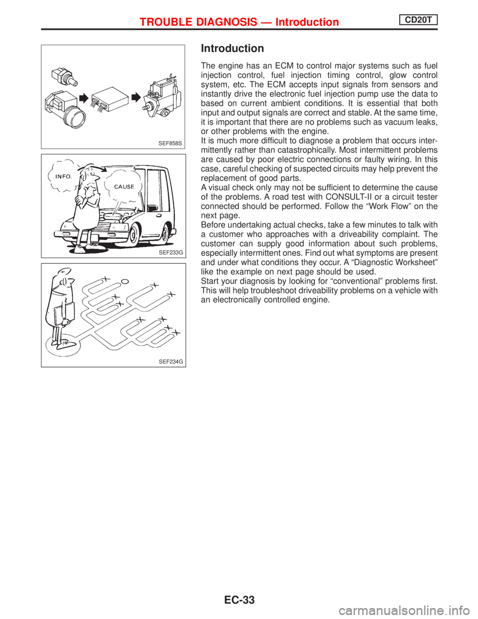
The engine has an ECM to control major systems such as fuel
injection control, fuel injection timing control, glow control
system, etc. The ECM accepts input signals from sensors and
instantly drive the electronic fuel injection pump use the data to
based on current ambient conditions. It is essential that both
input and output signals are correct and stable. At the same time,
it is important that there are no problems such as vacuum leaks,
or other problems with the engine.
It is much more difficult to diagnose a problem that occurs inter-
mittently rather than catastrophically. Most intermittent problems
are caused by poor electric connections or faulty wiring. In this
case, careful checking of suspected circuits may help prevent the
replacement of good parts.
A visual check only may not be sufficient to determine the cause
of the problems. A road test with CONSULT-II or a circuit tester
connected should be performed. Follow the ªWork Flowº on the
next page.
Before undertaking actual checks, take a few minutes to talk with
a customer who approaches with a driveability complaint. The
customer can supply good information about such problems,
especially intermittent ones. Find out what symptoms are present
and under what conditions they occur. A ªDiagnostic Worksheetº
like the example on next page should be used.
Start your diagnosis by looking for ªconventionalº problems first.
This will help troubleshoot driveability problems on a vehicle with
an electronically controlled engine.
SEF858S
SEF233G
SEF234G
TROUBLE DIAGNOSIS Ð IntroductionCD20T
EC-33
Page 330 of 2267
Description for Work Flow
STEP DESCRIPTION
STEP IGet detailed information about the conditions and the environment when the incident/symptom occurred
using the ªDIAGNOSTIC WORKSHEETº as shown on the previous page.
STEP IIBefore confirming the concern, check and write down (print out using CONSULT-II) the malfunction item,
then erase the code. The malfunction item can be used when duplicating the incident at STEP III & IV.
Study the relationship between the cause, specified by malfunction item, and the symptom described by the
customer. (The ªSymptom Matrix Chartº will be useful. Refer to EC-CD-47.)
STEP IIITry to confirm the symptom and under what conditions the incident occurs.
The ªDIAGNOSTIC WORK SHEETº is useful to verify the incident. Connect CONSULT-II to the vehicle in
DATA MONITOR (AUTO TRIG) mode and check real time diagnosis results.
If the incident cannot be verified, perform INCIDENT SIMULATION TESTS. Refer to GI section.
If the malfunction code is detected, skip STEP IV and perform STEP V.
STEP IVTry to detect the malfunction item by driving in (or performing) the ªDIAGNOSTIC TROUBLE CONFIRMA-
TION PROCEDUREº. Check and read the malfunction item by using CONSULT-II.
During the malfunction item verification, be sure to connect CONSULT-II to the vehicle in DATA MONITOR
(AUTO TRIG) mode and check real time diagnosis results.
If the incident cannot be verified, perform INCIDENT SIMULATION TESTS. Refer to GI section.
In case the ªDIAGNOSTIC TROUBLE CONFIRMATION PROCEDUREº is not available, perform the ªOVER-
ALL FUNCTION CHECKº instead. The malfunction item cannot be displayed by this check, however, this
simplified ªcheckº is an effective alternative.
The ªNGº result of the ªOVERALL FUNCTION CHECKº is the same as the DTC detection.
STEP VTake the appropriate action based on the results of STEP I through IV.
If the malfunction code is indicated, proceed to specific TROUBLE DIAGNOSIS for the malfunction item.
If the normal code is indicated, proceed to the BASIC INSPECTION. Refer to EC-CD-37. Then perform
inspections according to the Symptom Matrix Chart. Refer to EC-CD-47.
STEP VIIdentify where to begin diagnosis based on the relationship study between symptom and possible causes.
Inspect the system for mechanical binding, loose connectors or wiring damage using (tracing) ªHarness Lay-
outsº.
Gently shake the related connectors, components or wiring harness with CONSULT-II set in ªDATA MONI-
TOR (AUTO TRIG)º mode.
Check the voltage of the related ECM terminals or monitor the output data from the related sensors with
CONSULT-II. Refer to EC-CD-52.
The ªDIAGNOSTIC PROCEDUREº in EC section contains a description based on open circuit inspection. A
short circuit inspection is also required for the circuit check in the DIAGNOSTIC PROCEDURE. For details,
refer to GI section (ªCircuit Inspectionº, ªHOW TO PERFORM EFFICIENT DIAGNOSIS FOR AN ELECTRI-
CAL INCIDENTº).
Repair or replace the malfunctioning parts.
STEP VIIOnce you have repaired the circuit or replaced a component, you need to run the engine in the same condi-
tions and circumstances which resulted in the customer's initial complaint.
Perform the ªDIAGNOSTIC TROUBLE CONFIRMATION PROCEDUREº and confirm the normal code is
detected. If the incident is still detected in the final check, perform STEP VI by using a different method from
the previous one.
Before returning the vehicle to the customer, be sure to erase the unnecessary (already fixed) malfunction
item in ECM.
TROUBLE DIAGNOSIS Ð Work FlowCD20T
EC-36
Page 331 of 2267
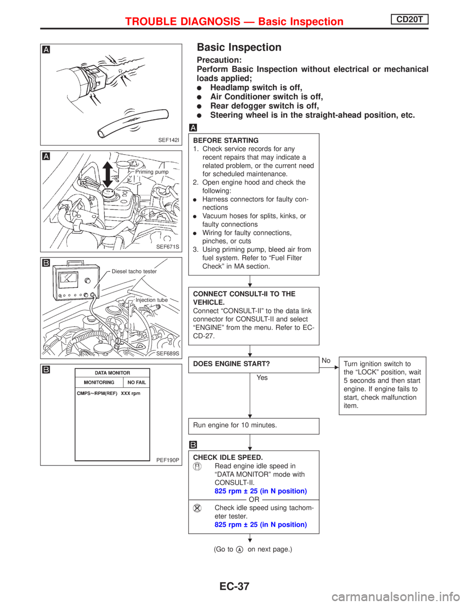
Basic Inspection
Precaution:
Perform Basic Inspection without electrical or mechanical
loads applied;
lHeadlamp switch is off,
lAir Conditioner switch is off,
lRear defogger switch is off,
lSteering wheel is in the straight-ahead position, etc.
BEFORE STARTING
1. Check service records for any
recent repairs that may indicate a
related problem, or the current need
for scheduled maintenance.
2. Open engine hood and check the
following:
lHarness connectors for faulty con-
nections
lVacuum hoses for splits, kinks, or
faulty connections
lWiring for faulty connections,
pinches, or cuts
3. Using priming pump, bleed air from
fuel system. Refer to ªFuel Filter
Checkº in MA section.
CONNECT CONSULT-II TO THE
VEHICLE.
Connect ªCONSULT-IIº to the data link
connector for CONSULT-II and select
ªENGINEº from the menu. Refer to EC-
CD-27.
DOES ENGINE START?
Ye s
ENo
Turn ignition switch to
the ªLOCKº position, wait
5 seconds and then start
engine. If engine fails to
start, check malfunction
item.
Run engine for 10 minutes.
CHECK IDLE SPEED.
Read engine idle speed in
ªDATA MONITORº mode with
CONSULT-II.
825 rpm 25 (in N position)
---------------------------------------------------------------------------------------------------------------------------------OR---------------------------------------------------------------------------------------------------------------------------------
Check idle speed using tachom-
eter tester.
825 rpm 25 (in N position)
(Go topAon next page.)
SEF142I
SEF671S
Priming pump
SEF689S
.Diesel tacho tester
.Injection tube
PEF190P
H
H
H
H
H
TROUBLE DIAGNOSIS Ð Basic InspectionCD20T
EC-37
Page 443 of 2267
ENGINE CONTROL SYSTEM
SECTION
EC
CONTENTS
QG16I18DE
TROUBLE DIAGNOSIS - INDEX....................................6
Alphabetical & P No. Index for DTC ...........................6
PRECAUTIONS...............................................................9
Supplemental Restraint System (SRS)²AIR
BAG²and²SEAT BELT PRE-TENSIONER²...............9
Precautions for On Board Diagnostic (OBD)
System of Engine ........................................................9
Engine Fuel & Emission Control System ..................10
Precautions ................................................................ 11
Wiring Diagrams and Trouble Diagnosis ...................12
PREPARATION..............................................................13
Special Service Tools ................................................13
Commercial Service Tool ...........................................13
ENGINE AND EMISSION CONTROL OVERALL
SYSTEM.........................................................................14
Engine Control Component Parts Location ...............14
Circuit Diagram ..........................................................17
System Diagram ........................................................18
Vacuum Hose Drawing ..............................................19
System Chart .............................................................20
ENGINE AND EMISSION BASIC CONTROL
SYSTEM DESCRIPTION...............................................21
Multiport Fuel Injection (MFI) System .......................21
Electronic Ignition (EI) System ..................................23
Air Conditioning Cut Control ......................................24
Fuel Cut Control (at no load & high engine
speed) ........................................................................25
Evaporative Emission System ...................................25
Positive Crankcase Ventilation ..................................28
BASIC SERVICE PROCEDURE...................................29
Fuel Pressure Release ..............................................29
Fuel Pressure Check .................................................29
Fuel Pressure Regulator Check ................................30
Injector .......................................................................30
Idle Speed/Ignition Timing/Idle Mixture Ratio
Adjustment .................................................................32Idle Air Volume Learning ...........................................33
ON BOARD DIAGNOSTIC SYSTEM
DESCRIPTION...............................................................36
Introduction ................................................................36
Two Trip Detection Logic ...........................................36
Emission-related Diagnostic Information ...................37
Malfunction Indicator (MI) ..........................................45
OBD System Operation Chart ...................................50
CONSULT-II ...............................................................55
Generic Scan Tool (GST) ..........................................66
TROUBLE DIAGNOSIS - INTRODUCTION..................68
Introduction ................................................................68
Work Flow ..................................................................70
TROUBLE DIAGNOSIS - BASIC INSPECTION...........72
Basic Inspection.........................................................72
TROUBLE DIAGNOSIS - GENERAL
DESCRIPTION...............................................................80
DTC Inspection Priority Chart....................................80
Fail-safe Chart ...........................................................81
Symptom Matrix Chart ...............................................82
CONSULT-II Reference Value in Data Monitor
Mode ..........................................................................86
Major Sensor Reference Graph in Data Monitor
Mode ..........................................................................88
ECM Terminals and Reference Value .......................91
TROUBLE DIAGNOSIS - SPECIFICATION VALUE....98
Description .................................................................98
Testing Condition .......................................................98
Inspection Procedure .................................................98
Diagnostic Procedure ................................................99
TROUBLE DIAGNOSIS FOR INTERMITTENT
INCIDENT.....................................................................102
Description ...............................................................102
Diagnostic Procedure ..............................................102
TROUBLE DIAGNOSIS FOR POWER SUPPLY........103
Main Power Supply and Ground Circuit ..................103
EC
Page 444 of 2267
DTC P0100 MASS AIR FLOW SENSOR (MAFS)...... 110
Component Description ........................................... 110
CONSULT-II Reference Value in Data Monitor
Mode ........................................................................ 110
ECM Terminals and Reference Value ..................... 110
On Board Diagnosis Logic....................................... 110
DTC Confirmation Procedure .................................. 111
Wiring Diagram ........................................................ 112
Diagnostic Procedure .............................................. 113
Component Inspection ............................................. 115
DTC P0110 INTAKE AIR TEMPERATURE
SENSOR...................................................................... 116
Component Description ........................................... 116
On Board Diagnosis Logic....................................... 116
DTC Confirmation Procedure .................................. 116
Wiring Diagram ........................................................ 117
Diagnostic Procedure .............................................. 118
Component Inspection ............................................. 119
DTC P0115 ENGINE COOLANT TEMPERATURE
SENSOR (ECTS) (CIRCUIT).......................................120
Component Description ...........................................120
CONSULT-II Reference Value in Data Monitor
Mode ........................................................................120
On Board Diagnosis Logic.......................................120
DTC Confirmation Procedure ..................................121
Wiring Diagram ........................................................122
Diagnostic Procedure ..............................................123
Component Inspection .............................................124
DTC P0120 THROTTLE POSITION SENSOR...........125
Component Description ...........................................125
CONSULT-II Reference Value in Data Monitor
Mode ........................................................................125
ECM Terminals and Reference Value .....................126
On Board Diagnosis Logic.......................................126
DTC Confirmation Procedure ..................................126
Wiring Diagram ........................................................128
Diagnostic Procedure ..............................................129
Component Inspection .............................................131
DTC P0130 HEATED OXYGEN SENSOR 1
(FRONT) (CIRCUIT).....................................................132
Component Description ...........................................132
CONSULT-II Reference Value in Data Monitor
Mode ........................................................................132
ECM Terminals and Reference Value .....................132
On Board Diagnosis Logic.......................................133
DTC Confirmation Procedure ..................................133
Overall Function Check ...........................................134
Wiring Diagram ........................................................135
Diagnostic Procedure ..............................................136
Component Inspection .............................................137DTC P0131 HEATED OXYGEN SENSOR 1
(FRONT) (LEAN SHIFT MONITORING).....................139
Component Description ...........................................139
CONSULT-II Reference Value in Data Monitor
Mode ........................................................................139
ECM Terminals and Reference Value .....................139
On Board Diagnosis Logic.......................................140
DTC Confirmation Procedure ..................................140
Overall Function Check ...........................................141
Diagnostic Procedure ..............................................141
Component Inspection .............................................143
DTC P0132 HEATED OXYGEN SENSOR 1
(FRONT) (RICH SHIFT MONITORING)......................145
Component Description ...........................................145
CONSULT-II Reference Value in Data Monitor
Mode ........................................................................145
ECM Terminals and Reference Value .....................145
On Board Diagnosis Logic.......................................146
DTC Confirmation Procedure ..................................146
Overall Function Check ...........................................147
Diagnostic Procedure ..............................................147
Component Inspection .............................................149
DTC P0133 HEATED OXYGEN SENSOR 1
(FRONT) (RESPONSE MONITORING).......................151
Component Description ...........................................151
CONSULT-II Reference Value in Data Monitor
Mode ........................................................................151
ECM Terminals and Reference Value .....................151
On Board Diagnosis Logic.......................................152
DTC Confirmation Procedure ..................................152
Overall Function Check ...........................................153
Wiring Diagram ........................................................154
Diagnostic Procedure ..............................................155
Component Inspection .............................................158
DTC P0134 HEATED OXYGEN SENSOR 1
(FRONT) (HIGH VOLTAGE)........................................160
Component Description ...........................................160
CONSULT-II Reference Value in Data Monitor
Mode ........................................................................160
ECM Terminals and Reference Value .....................160
On Board Diagnosis Logic.......................................161
DTC Confirmation Procedure ..................................161
Wiring Diagram ........................................................162
Diagnostic Procedure ..............................................163
Component Inspection .............................................164
DTC P0135 HEATED OXYGEN SENSOR 1
(FRONT) HEATER.......................................................166
Description ...............................................................166
CONSULT-II Reference Value in Data Monitor
Mode ........................................................................166
ECM Terminals and Reference Value .....................166
On Board Diagnosis Logic.......................................166
CONTENTS(Cont'd)
EC-2
Page 445 of 2267
DTC Confirmation Procedure ..................................167
Wiring Diagram ........................................................168
Diagnostic Procedure ..............................................169
Component Inspection .............................................170
DTC P0137 HEATED OXYGEN SENSOR 2
(REAR) (MIN. VOLTAGE MONITORING)...................171
Component Description ...........................................171
CONSULT-II Reference Value in Data Monitor
Mode ........................................................................171
ECM Terminals and Reference Value .....................171
On Board Diagnosis Logic.......................................171
DTC Confirmation Procedure ..................................172
Overall Function Check ...........................................173
Wiring Diagram ........................................................174
Diagnostic Procedure ..............................................175
Component Inspection .............................................178
DTC P0138 HEATED OXYGEN SENSOR 2
(REAR) (MAX. VOLTAGE MONITORING).................180
Component Description ...........................................180
CONSULT-II Reference Value in Data Monitor
Mode ........................................................................180
ECM Terminals and Reference Value .....................180
On Board Diagnosis Logic.......................................180
DTC Confirmation Procedure ..................................181
Overall Function Check ...........................................182
Wiring Diagram ........................................................183
Diagnostic Procedure ..............................................184
Component Inspection .............................................186
DTC P0139 HEATED OXYGEN SENSOR 2
(REAR) (RESPONSE MONITORING).........................188
Component Description ...........................................188
CONSULT-II Reference Value in Data Monitor
Mode ........................................................................188
ECM Terminals and Reference Value .....................188
On Board Diagnosis Logic.......................................188
DTC Confirmation Procedure ..................................189
Overall Function Check ...........................................190
Wiring Diagram ........................................................191
Diagnostic Procedure ..............................................192
Component Inspection .............................................195
DTC P0140 HEATED OXYGEN SENSOR 2
(REAR) (HIGH VOLTAGE)..........................................197
Component Description ...........................................197
CONSULT-II Reference Value in Data Monitor
Mode ........................................................................197
ECM Terminals and Reference Value .....................197
On Board Diagnosis Logic.......................................197
DTC Confirmation Procedure ..................................198
Overall Function Check ...........................................198
Wiring Diagram ........................................................199
Diagnostic Procedure ..............................................200
Component Inspection .............................................201DTC P0141 HEATED OXYGEN SENSOR 2
HEATER (REAR).........................................................203
Description ...............................................................203
CONSULT-II Reference Value in Data Monitor
Mode ........................................................................203
ECM Terminals and Reference Value .....................203
On Board Diagnosis Logic.......................................204
DTC Confirmation Procedure ..................................204
Wiring Diagram ........................................................205
Diagnostic Procedure ..............................................206
Component Inspection .............................................207
DTC P0171 FUEL INJECTION SYSTEM
FUNCTION (LEAN SIDE)............................................208
On Board Diagnosis Logic.......................................208
DTC Confirmation Procedure ..................................208
Wiring Diagram ........................................................210
Diagnostic Procedure .............................................. 211
DTC P0172 FUEL INJECTION SYSTEM
FUNCTION (RICH SIDE).............................................215
On Board Diagnosis Logic.......................................215
DTC Confirmation Procedure ..................................215
Wiring Diagram ........................................................217
Diagnostic Procedure ..............................................218
DTC P0300 - P0304 NO.4-1CYLINDER
MISFIRE, MULTIPLE CYLINDER MISFIRE................222
On Board Diagnosis Logic.......................................222
DTC Confirmation Procedure ..................................222
Diagnostic Procedure ..............................................223
DTC P0325 KNOCK SENSOR (KS)...........................228
Component Description ...........................................228
ECM Terminals and Reference Value .....................228
On Board Diagnosis Logic.......................................228
DTC Confirmation Procedure ..................................228
Wiring Diagram ........................................................229
Diagnostic Procedure ..............................................230
Component Inspection .............................................231
DTC P0335 CRANKSHAFT POSITION SENSOR
(POS)............................................................................232
Component Description ...........................................232
ECM Terminals and Reference Value .....................232
On Board Diagnosis Logic.......................................233
DTC Confirmation Procedure ..................................233
Wiring Diagram ........................................................234
Diagnostic Procedure ..............................................235
Component Inspection .............................................237
DTC P0340 CAMSHAFT POSITION SENSOR
(CMPS) (PHASE).........................................................238
Component Description ...........................................238
ECM Terminals and Reference Value .....................238
On Board Diagnosis Logic.......................................238
DTC Confirmation Procedure ..................................239
Wiring Diagram ........................................................240
CONTENTS(Cont'd)
EC-3