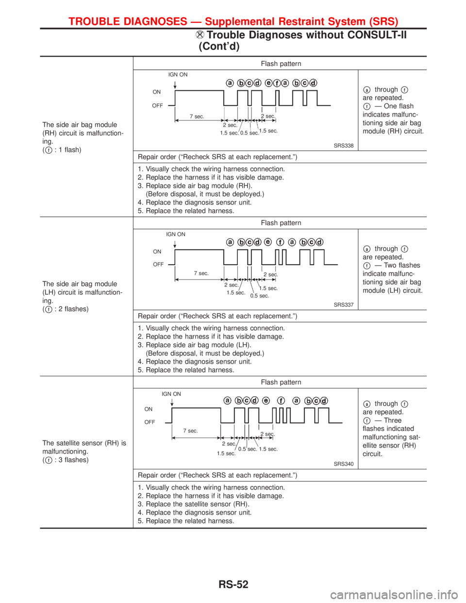
The side air bag module
(RH) circuit is malfunction-
ing.
(
pf: 1 flash)Flash patternSRS338
pathroughpf
are repeated.
pfÐ One flash
indicates malfunc-
tioning side air bag
module (RH) circuit.
Repair order (ªRecheck SRS at each replacement.º)
1. Visually check the wiring harness connection.
2. Replace the harness if it has visible damage.
3. Replace side air bag module (RH).
(Before disposal, it must be deployed.)
4. Replace the diagnosis sensor unit.
5. Replace the related harness.
The side air bag module
(LH) circuit is malfunction-
ing.
(
pf: 2 flashes)Flash patternSRS337
pathroughpf
are repeated.
pfÐ Two flashes
indicate malfunc-
tioning side air bag
module (LH) circuit.
Repair order (ªRecheck SRS at each replacement.º)
1. Visually check the wiring harness connection.
2. Replace the harness if it has visible damage.
3. Replace side air bag module (LH).
(Before disposal, it must be deployed.)
4. Replace the diagnosis sensor unit.
5. Replace the related harness.
The satellite sensor (RH) is
malfunctioning.
(
pf: 3 flashes)Flash patternSRS340
pathroughpf
are repeated.
pfÐ Three
flashes indicated
malfunctioning sat-
ellite sensor (RH)
circuit.
Repair order (ªRecheck SRS at each replacement.º)
1. Visually check the wiring harness connection.
2. Replace the harness if it has visible damage.
3. Replace the satellite sensor (RH).
4. Replace the diagnosis sensor unit.
5. Replace the related harness.
IGN ON
ON
OFF
7 sec.
2 sec.2 sec.
1.5 sec.
0.5 sec. 1.5 sec.
IGN ON
ON
OFF
7 sec.
2 sec.
1.5 sec.
0.5 sec.1.5 sec.2 sec.
IGN ON
ON
OFF
7 sec.
2 sec.
1.5 sec. 0.5 sec.
1.5 sec.2 sec.
TROUBLE DIAGNOSES Ð Supplemental Restraint System (SRS)
Trouble Diagnoses without CONSULT-II
(Cont'd)
RS-52
DIAGNOSTIC PROCEDURE 7
Final checking after repairing SRS by using ªAIR BAGº
warning lamp Ð Diagnosis mode and User mode
1. After repairing SRS connect both battery cables.
2. Turn ignition switch from ªOFFº to ªONº.
3. ªAIR BAGº warning lamp operates in Diagnosis mode as fol-
lows:
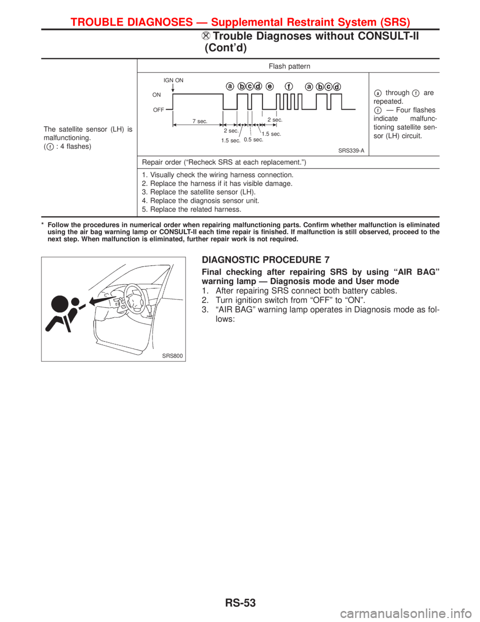
The satellite sensor (LH) is
malfunctioning.
(
pf: 4 flashes)Flash patternSRS339-A
pathroughpfare
repeated.
pfÐ Four flashes
indicate malfunc-
tioning satellite sen-
sor (LH) circuit.
Repair order (ªRecheck SRS at each replacement.º)
1. Visually check the wiring harness connection.
2. Replace the harness if it has visible damage.
3. Replace the satellite sensor (LH).
4. Replace the diagnosis sensor unit.
5. Replace the related harness.
* Follow the procedures in numerical order when repairing malfunctioning parts. Confirm whether malfunction is eliminated
using the air bag warning lamp or CONSULT-II each time repair is finished. If malfunction is still observed, proceed to the
next step. When malfunction is eliminated, further repair work is not required.
IGN ON
ON
OFF
7 sec.2 sec.
2 sec.
1.5 sec.
1.5 sec.0.5 sec.
SRS800
TROUBLE DIAGNOSES Ð Supplemental Restraint System (SRS)
Trouble Diagnoses without CONSULT-II
(Cont'd)
RS-53
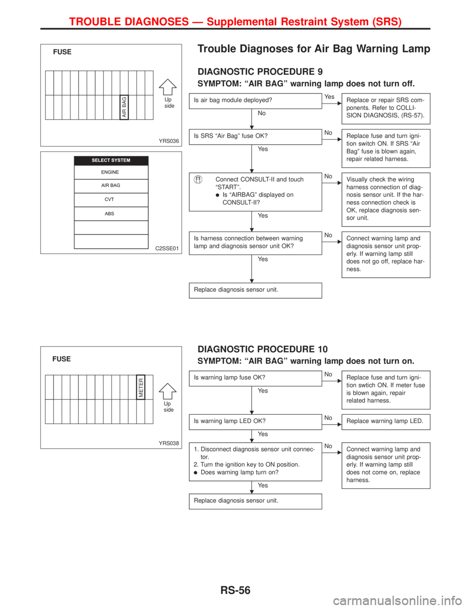
Trouble Diagnoses for Air Bag Warning Lamp
DIAGNOSTIC PROCEDURE 9
SYMPTOM: ªAIR BAGº warning lamp does not turn off.
Is air bag module deployed?
No
EYe s
Replace or repair SRS com-
ponents. Refer to COLLI-
SION DIAGNOSIS, (RS-57).
Is SRS ªAir Bagº fuse OK?
Ye s
ENo
Replace fuse and turn igni-
tion switch ON. If SRS ªAir
Bagº fuse is blown again,
repair related harness.
Connect CONSULT-II and touch
ªSTARTº.
lIs ªAIRBAGº displayed on
CONSULT-II?
Ye s
ENo
Visually check the wiring
harness connection of diag-
nosis sensor unit. If the har-
ness connection check is
OK, replace diagnosis sen-
sor unit.
Is harness connection between warning
lamp and diagnosis sensor unit OK?
Ye s
ENo
Connect warning lamp and
diagnosis sensor unit prop-
erly. If warning lamp still
does not go off, replace har-
ness.
Replace diagnosis sensor unit.
DIAGNOSTIC PROCEDURE 10
SYMPTOM: ªAIR BAGº warning lamp does not turn on.
Is warning lamp fuse OK?
Ye s
ENo
Replace fuse and turn igni-
tion swtich ON. If meter fuse
is blown again, repair
related harness.
Is warning lamp LED OK?
Ye s
ENo
Replace warning lamp LED.
1. Disconnect diagnosis sensor unit connec-
tor.
2. Turn the ignition key to ON position.
lDoes warning lamp turn on?
Ye s
ENo
Connect warning lamp and
diagnosis sensor unit prop-
erly. If warning lamp still
does not come on, replace
harness.
Replace diagnosis sensor unit.
YRS036
FUSE
Up
side
AIR BAG
C2SSE01
YRS038
FUSE
Up
side
METER
H
H
H
H
H
H
H
TROUBLE DIAGNOSES Ð Supplemental Restraint System (SRS)
RS-56
Precautions
Supplemental Restraint System (SRS) ªAIR BAGº
and ªSEAT BELT PRE-TENSIONERº
The Supplemental Restraint System ªAir Bagº and ªSeat Belt Pre-tensionerº, used along with a seat belt,
help to reduce the risk or severity of injury to the driver and front passenger in a frontal collision. The
Supplemental Restraint System consists of air bag modules (located in the center of the steering wheel and
on the instrument panel on the passenger side), seat belt pre-tensioners, a diagnosis sensor unit, warning
lamp, wiring harness and spiral cable.
If the vehicle is equipped with side air bag as the Supplemental Restraint System, the side air bag used along
with the seat belt helps to reduce the risk or severity of injury to the driver and front passenger in a side
collision. The side air bag consists of air bag modules (located in the outer side of front seats), satellite
sensor, diagnosis sensor unit (which is one of components of air bags for a frontal collision), wiring harness,
warning lamp (which is one of components of air bags for a frontal collision).
WARNING:
lTo avoid rendering the SRS inoperative, which could increase the risk of personal injury or death
(in the event of a collision which would result in air bag inflation), all maintenance must be per-
formed by an authorized NISSAN dealer.
lImproper maintenance, including incorrect removal and installation of the SRS, can lead to per-
sonal injury caused by unintentional activation of the system.
lDo not use electrical test equipment on any circuit related to the SRS unless instructed to do so
in this Service Manual. SRS wiring harnesses are covered with yellow insulation (either just
before the harness connectors or for the complete harness), for easy identification.
STEERING SYSTEM
lBefore disassembly, thoroughly clean the outside of the unit.
lDisassembly should be done in a clean work area. It is important to prevent the internal parts
from becoming contaminated by dirt or other foreign matter.
lWhen disassembling parts, be sure to place them in order on a part rack so they can be rein-
stalled in their correct positions.
lOnly use nylon cloths or paper towels to clean parts. Do not use rags or other materials contain-
ing lint. Residual debris may damage the system.
lBefore inspection or reassembly, carefully clean all parts with a general purpose, non-flammable
solvent.
lBefore assembly, apply a coat of recommended ATF* to hydraulic parts. Vaseline may be applied
to O-rings and seals. Do not use any grease.
lReplace all gaskets, seals and O-rings. Avoid damaging O-rings, seals and gaskets during instal-
lation. Perform functional tests whenever designated.
*: Automatic transmission fluid
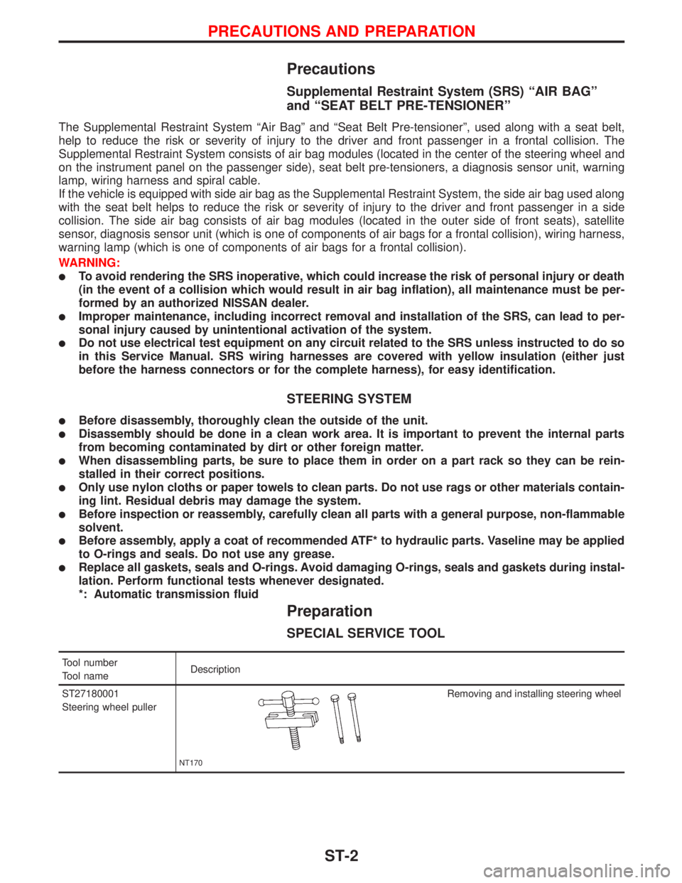
Preparation
SPECIAL SERVICE TOOL
Tool number
Tool nameDescription
ST27180001
Steering wheel puller
NT170
Removing and installing steering wheel
PRECAUTIONS AND PREPARATION
ST-2