1999 NISSAN PRIMERA tow
[x] Cancel search: towPage 1843 of 2267
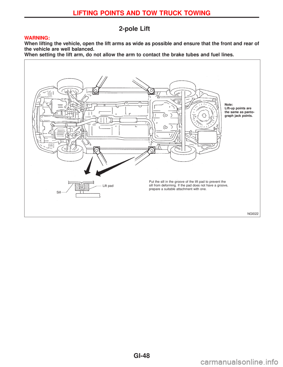
2-pole Lift
WARNING:
When lifting the vehicle, open the lift arms as wide as possible and ensure that the front and rear of
the vehicle are well balanced.
When setting the lift arm, do not allow the arm to contact the brake tubes and fuel lines.
NGI022 Note:
Lift-up points are
the same as panto-
graph jack points.
SillLift padPut the sill in the groove of the lift pad to prevent the
sill from deforming. If the pad does not have a groove,
prepare a suitable attachment with one.
LIFTING POINTS AND TOW TRUCK TOWING
GI-48
Page 1844 of 2267
Tow Truck Towing
CAUTION:
lAll applicable local laws regarding the towing operation
must be obeyed.
lIt is necessary to use proper towing equipment to avoid
possible damage to the vehicle during towing operation.
Towing is in accordance with Towing Procedure Manual
at dealer.
lWhen towing with the rear wheels on the ground, release
the parking brake and move the gearshift lever to neu-
tral position.
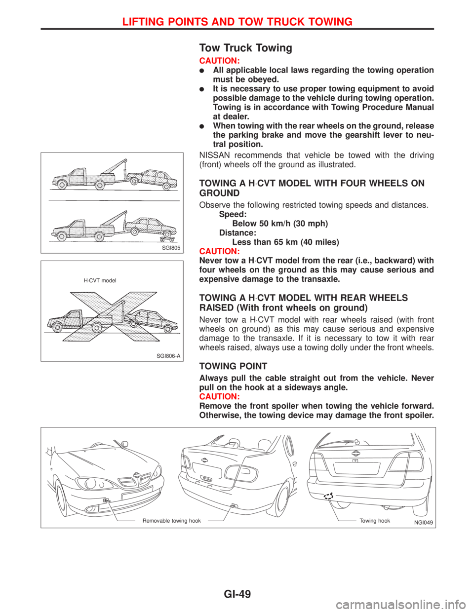
NISSAN recommends that vehicle be towed with the driving
(front) wheels off the ground as illustrated.
TOWING A H×CVT MODEL WITH FOUR WHEELS ON
GROUND
Observe the following restricted towing speeds and distances.
Speed:
Below 50 km/h (30 mph)
Distance:
Less than 65 km (40 miles)
CAUTION:
Never tow a H×CVT model from the rear (i.e., backward) with
four wheels on the ground as this may cause serious and
expensive damage to the transaxle.
TOWING A H×CVT MODEL WITH REAR WHEELS
RAISED (With front wheels on ground)
Never tow a H×CVT model with rear wheels raised (with front
wheels on ground) as this may cause serious and expensive
damage to the transaxle. If it is necessary to tow it with rear
wheels raised, always use a towing dolly under the front wheels.
TOWING POINT
Always pull the cable straight out from the vehicle. Never
pull on the hook at a sideways angle.
CAUTION:
Remove the front spoiler when towing the vehicle forward.
Otherwise, the towing device may damage the front spoiler.
SGI805
SGI806-A H×CVT model
NGI049 Towing hook Removable towing hook
LIFTING POINTS AND TOW TRUCK TOWING
GI-49
Page 1937 of 2267
system operation. On the other hand, shortly after entering a
long tunnel, the system will recognize the change in sunload, and
the system will react accordingly.
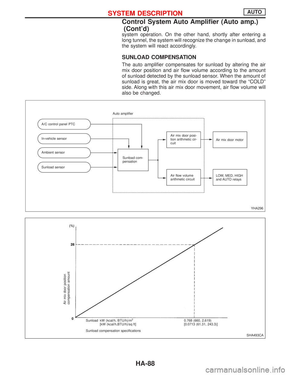
SUNLOAD COMPENSATION
The auto amplifier compensates for sunload by altering the air
mix door position and air flow volume according to the amount
of sunload detected by the sunload sensor. When the amount of
sunload is great, the air mix door is moved toward the ªCOLDº
side. Along with this air mix door movement, air flow volume will
also be changed.
YHA296 A/C control panel PTC
In-vehicle sensor
Ambient sensor
Sunload sensorSunload com-
pensation Auto amplifier
Air mix door posi-
tion arithmetic cir-
cuit
Air flow volume
arithmetic circuitAir mix door motor
LOW, MED, HIGH
and AUTO relays
SHA493CA
Air mix door position
compensation amount
Sunload kW (kcal/h, BTU/h)/m2
[kW (kcal/h,BTU/h)/sq ft]
Sunload compensation specifications0.768 (660, 2,619)
[0.0713 (61.31, 243.3)]
SYSTEM DESCRIPTIONAUTO
Control System Auto Amplifier (Auto amp.)
(Cont'd)
HA-88
Page 1938 of 2267
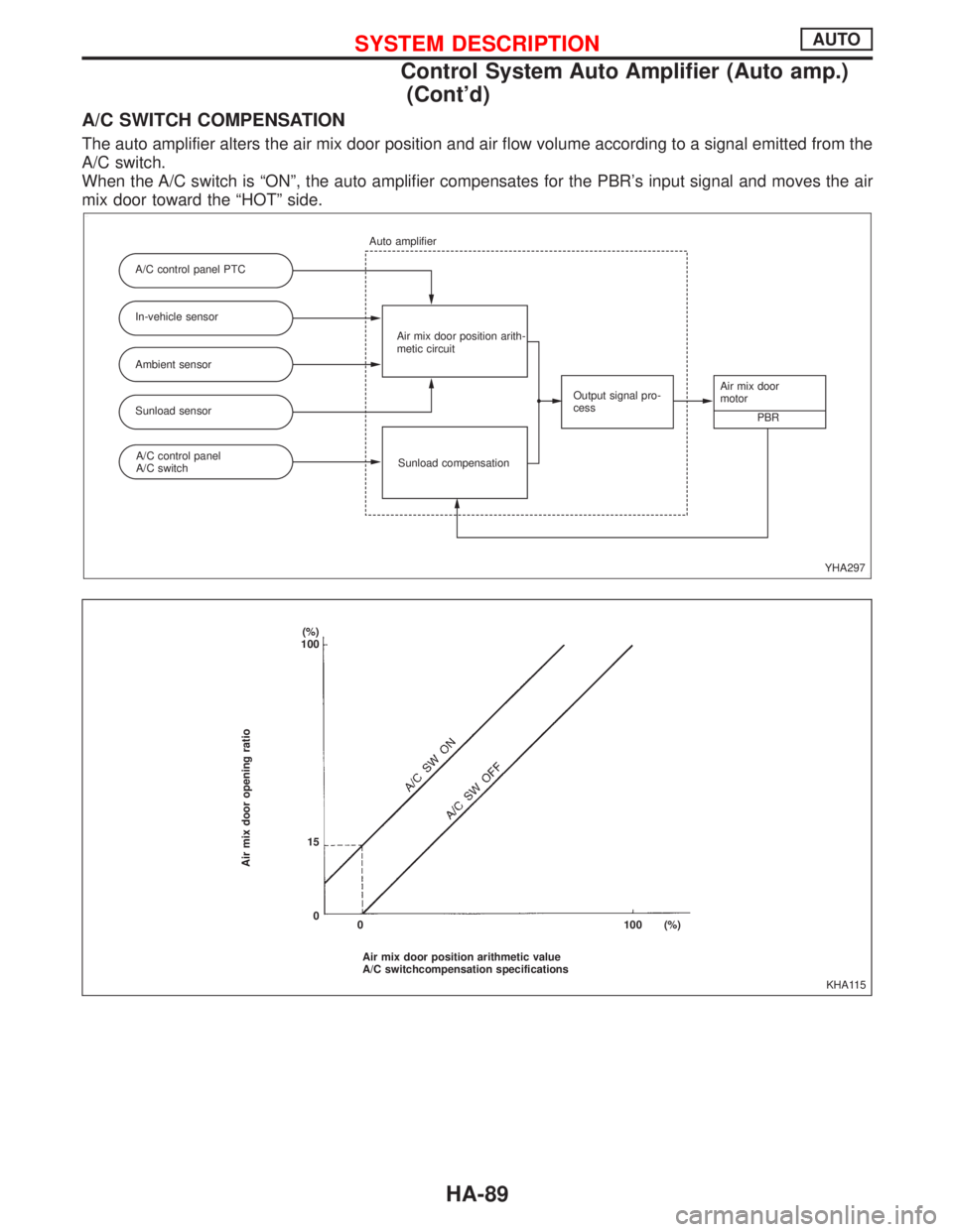
A/C SWITCH COMPENSATION
The auto amplifier alters the air mix door position and air flow volume according to a signal emitted from the
A/C switch.
When the A/C switch is ªONº, the auto amplifier compensates for the PBR's input signal and moves the air
mix door toward the ªHOTº side.
YHA297 A/C control panel PTC
In-vehicle sensor
Ambient sensor
Sunload sensor
Sunload compensation Auto amplifier
Air mix door position arith-
metic circuit
Output signal pro-
cessAir mix door
motor
PBR
A/C control panel
A/C switch
KHA115
Air mix door opening ratio
(%)
100
15
0
Air mix door position arithmetic value
A/C switchcompensation specifications 0 100 (%)
SYSTEM DESCRIPTIONAUTO
Control System Auto Amplifier (Auto amp.)
(Cont'd)
HA-89
Page 1941 of 2267
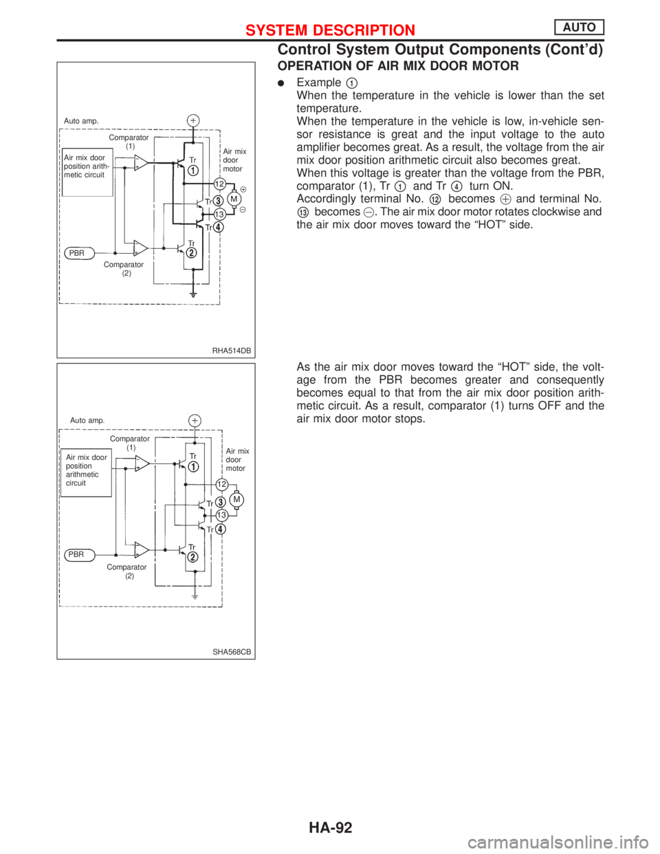
OPERATION OF AIR MIX DOOR MOTOR
lExamplep1
When the temperature in the vehicle is lower than the set
temperature.
When the temperature in the vehicle is low, in-vehicle sen-
sor resistance is great and the input voltage to the auto
amplifier becomes great. As a result, the voltage from the air
mix door position arithmetic circuit also becomes great.
When this voltage is greater than the voltage from the PBR,
comparator (1), Tr
p1and Trp4turn ON.
Accordingly terminal No.
p12becomes!and terminal No.
p13becomes@. The air mix door motor rotates clockwise and
the air mix door moves toward the ªHOTº side.
As the air mix door moves toward the ªHOTº side, the volt-
age from the PBR becomes greater and consequently
becomes equal to that from the air mix door position arith-
metic circuit. As a result, comparator (1) turns OFF and the
air mix door motor stops.
RHA514DB Auto amp.
Comparator
(1)
Air mix door
position arith-
metic circuitAir mix
door
motor
PBR
Comparator
(2)
SHA568CB Auto amp.
Comparator
(1)
Air mix door
position
arithmetic
circuit
PBR
Comparator
(2)Air mix
door
motor
SYSTEM DESCRIPTIONAUTO
Control System Output Components (Cont'd)
HA-92
Page 1942 of 2267
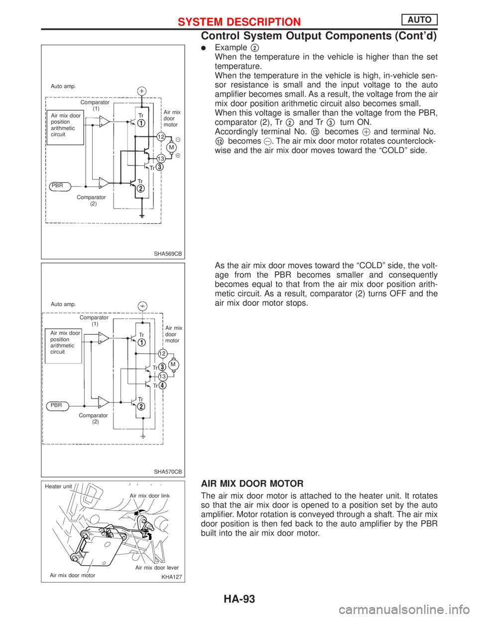
lExamplep2
When the temperature in the vehicle is higher than the set
temperature.
When the temperature in the vehicle is high, in-vehicle sen-
sor resistance is small and the input voltage to the auto
amplifier becomes small. As a result, the voltage from the air
mix door position arithmetic circuit also becomes small.
When this voltage is smaller than the voltage from the PBR,
comparator (2), Tr
p2and Trp3turn ON.
Accordingly terminal No.
p13becomes!and terminal No.
p12becomes@. The air mix door motor rotates counterclock-
wise and the air mix door moves toward the ªCOLDº side.
As the air mix door moves toward the ªCOLDº side, the volt-
age from the PBR becomes smaller and consequently
becomes equal to that from the air mix door position arith-
metic circuit. As a result, comparator (2) turns OFF and the
air mix door motor stops.
AIR MIX DOOR MOTOR
The air mix door motor is attached to the heater unit. It rotates
so that the air mix door is opened to a position set by the auto
amplifier. Motor rotation is conveyed through a shaft. The air mix
door position is then fed back to the auto amplifier by the PBR
built into the air mix door motor.
SHA569CB Auto amp.
Comparator
(1)
Air mix door
position
arithmetic
circuit
PBR
Comparator
(2)Air mix
door
motor
SHA570CB Auto amp.
Comparator
(1)
Air mix door
position
arithmetic
circuit
PBR
Comparator
(2)Air mix
door
motor
KHA127 Air mix door link
Air mix door lever
Air mix door motor Heater unit
SYSTEM DESCRIPTIONAUTO
Control System Output Components (Cont'd)
HA-93
Page 1943 of 2267
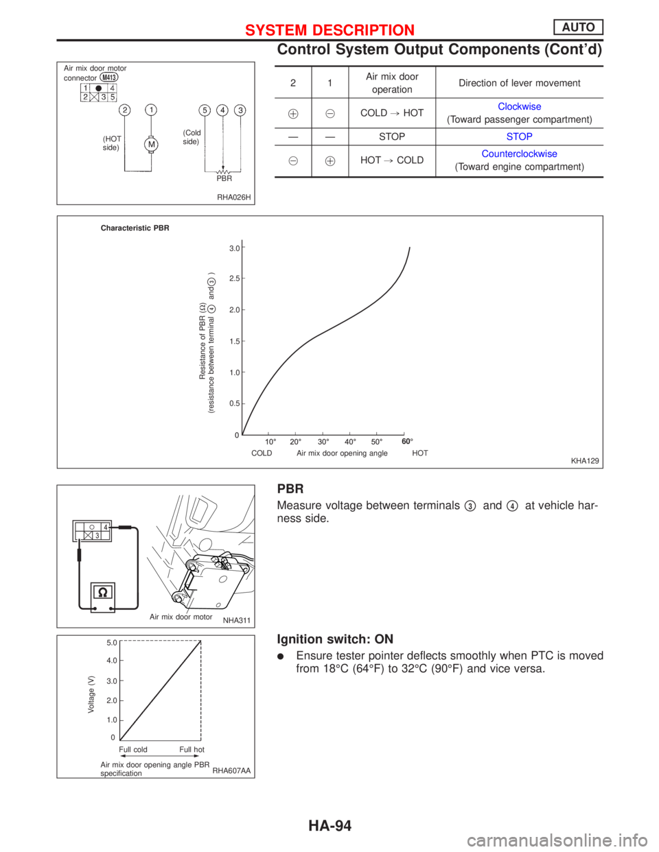
21Air mix door
operationDirection of lever movement
!@COLD,HOTClockwise
(Toward passenger compartment)
Ð Ð STOPSTOP
@
!HOT,COLDCounterclockwise
(Toward engine compartment)
PBR
Measure voltage between terminalsp3andp4at vehicle har-
ness side.
Ignition switch: ON
lEnsure tester pointer deflects smoothly when PTC is moved
from 18ÉC (64ÉF) to 32ÉC (90ÉF) and vice versa.
RHA026H Air mix door motor
connector
M413
(HOT
side)(Cold
side)
PBR
KHA129 Characteristic PBR
Resistance of PBR (W)
(resistance between terminal
p4and
p3)
.3.0
2.5
2.0
1.5
1.0
0.5
COLD Air mix door opening angle HOT60É
NHA311 Air mix door motor
RHA607AA
Voltage (V)
Full cold Full hot
Air mix door opening angle PBR
specification5.0
4.0
3.0
2.0
1.0
0
SYSTEM DESCRIPTIONAUTO
Control System Output Components (Cont'd)
HA-94
Page 1974 of 2267
S/SIG - Wiring diagram ....EC-QG-333, EC-SR-313,
EC-CD-145
Stabilizer bar (front) ........................................FA-32
Stall test (A/T) .................................................AT-34
Standardized relay ............................................EL-8
START - Wiring diagram .................................EL-37
Start signal .................EC-QG-38, 332, EC-SR-312,
EC-CD-145
Starter .......................................................EL-37, 43
Starting system ...............................................EL-37
Steering gear and linkage inspection ............MA-53
Steering knuckle........................................FA-11, 12
Stop lamp ......................................................EL-104
STOP/L - Wiring diagram..............................EL-104
Sun roof, electric ...........................................EL-230
Sunload sensor ..............................................HA-86
Sunroof .....................................................BT-31, 46
Super lock .............................................EL-245, 265
Supplemental Restraint System .......................RS-8
Supplemental restraint system - Wiring
diagram .......................................................RS-33
Symbols and abbreviations .............................GI-38
Symptom matrix chart ...........EC-QG-82, EC-SR-94
Synchronizer (M/T) ......................MT-22, 27, 59, 65
System readiness test (SRT) code ..........EC-SR-50
T
Tachometer ...........................................EL-141, 146
Tail lamp ........................................................EL-100
TCM circuit diagram ........................................AT-10
TCM inspection table ......................................AT-41
Temperature control cable and linkage
adjustment ..................................................HA-83
THEFT - Wiring diagram ...............................EL-316
Theft warning system ....................................EL-311
Thermal protector .........................................HA-113
Thermo control amp .......................................HA-80
Thermostat ..........................................LC-11, 23, 34
Third link (front susp.) .....................................FA-29
Three way catalyst ............EC-QG-258, EC-SR-246
Three way catalyst precautions.........................GI-6
Throttle position sensor
(TPS) .............................EC-QG-125, EC-SR-137
Throttle position sensor
adjustment .........................EC-QG-72, EC-SR-84
Throttle position switch ...............EC-SR-271, AT-85
Tightening torque of standard bolts.................GI-50
Time control system ......................................EL-306
Timing belt....................................................EM-131
Timing chain.............................................EM-19, 75
Tire rotation ....................................................MA-53
Tire size ...........................................................GI-45
Torque converter installation .........................AT-117
Torque convertor clutch solenoid valve...........AT-69
Tow truck towing ..............................................GI-46
Towing point.....................................................GI-49
TP/SW - Wiring diagram ........................EC-SR-273
TPS - Wiring diagram .......EC-QG-128, EC-SR-140
Transmission case (M/T) ................................MT-39Transverse link (front) .....................................FA-32
Trim .................................................................BT-18
Triple pressure switch ....................................HA-79
Trouble diagnoses ...........................................GI-35
Trunk lid ............................................................BT-7
Trunk lid opener - See Trunk lid .......................BT-7
Trunk room lamp...................................EL-130, 131
Trunk room trim...............................................BT-28
Turbocharger........................................EM-156, 201
Turbocharger precautions..................................GI-6
TURN - Wiring diagram.................................EL-118
Turn signal lamp............................................EL-117
Two trip detection logic .........EC-QG-36, EC-SR-48
U
Upper link (front susp.) ...................................FA-29
V
Vacuum hose (brake system).........................BR-20
Vacuum hose drawing (Engine
control) ............EC-QG-19, EC-SR-21, EC-CD-13
Valve clearance .............................EM-40, 179, 191
Valve guide..............EM-36, 93, 142, 180, 189, 197
Valve lifter ..............................EM-40, 145, 179, 198
Valve seat................EM-38, 95, 143, 182, 190, 198
Valve spring.............EM-39, 96, 145, 179, 189, 197
Vehicle identification number...........................GI-43
Vehicle speed sensor
(VSS) ..........EC-QG-267, EC-SR-255, EC-CD-70
Viscosity number (SAE) .................................MA-17
VSS - Wiring
diagram .......EC-QG-269, EC-SR-257, EC-CD-71
W
WARN - Wiring diagram ...............................EL-167
Warning buzzer .............................................EL-180
Warning chime ..............................................EL-180
Warning lamps ..............................................EL-165
Washer, front .................................................EL-186
Washer, rear..................................................EL-193
Water cock control rod adjustment ................HA-82
Water pump ........................................LC-10, 22, 33
Water temperature gauge .....................EL-141, 146
Weatherstrip - See Exterior ............................BT-31
Wheel alignment (front) ..................................FA-35
Wheel alignment (rear).....................................RA-6
Wheel balance ...............................................MA-53
Wheel bearing (front axle) ....................FA-6, 12, 35
Wheel bearing (rear) ........................................RA-5
Wheel hub (front) ............................................FA-12
Wheel hub (rear) ..............................................RA-7
Wheel sensors (ABS) .....................................BR-53
Wheel size .......................................................GI-45
Wheelbase (Dimensions) ................................GI-45
ALPHABETICAL INDEX
IDX-7