Precautions
Supplemental Restraint System (SRS) ªAIR BAGº
and ªSEAT BELT PRE-TENSIONERº
The Supplemental Restraint System ªAir Bagº and ªSeat Belt Pre-tensionerº, used along with a seat belt,
help to reduce the risk or severity of injury to the driver and front passenger in a frontal collision. The
Supplemental Restraint System consists of air bag modules (located in the center of the steering wheel and
on the instrument panel on the passenger side), seat belt pre-tensioners, a diagnosis sensor unit, warning
lamp, wiring harness and spiral cable.
If the vehicle is equipped with side air bag as the Supplemental Restraint System, the side air bag used along
with the seat belt helps to reduce the risk or severity of injury to the driver and front passenger in a side
collision. The side air bag consists of air bag modules (located in the outer side of front seats), satellite
sensor, diagnosis sensor unit (which is one of components of air bags for a frontal collision), wiring harness,
warning lamp (which is one of components of air bags for a frontal collision).
WARNING:
lTo avoid rendering the SRS inoperative, which could increase the risk of personal injury or death
(in the event of a collision which would result in air bag inflation), all maintenance must be per-
formed by an authorized NISSAN dealer.
lImproper maintenance, including incorrect removal and installation of the SRS, can lead to per-
sonal injury caused by unintentional activation of the system.
lDo not use electrical test equipment on any circuit related to the SRS unless instructed to do so
in this Service Manual. SRS wiring harnesses are covered with yellow insulation (either just
before the harness connectors or for the complete harness), for easy identification.
STEERING SYSTEM
lBefore disassembly, thoroughly clean the outside of the unit.
lDisassembly should be done in a clean work area. It is important to prevent the internal parts
from becoming contaminated by dirt or other foreign matter.
lWhen disassembling parts, be sure to place them in order on a part rack so they can be rein-
stalled in their correct positions.
lOnly use nylon cloths or paper towels to clean parts. Do not use rags or other materials contain-
ing lint. Residual debris may damage the system.
lBefore inspection or reassembly, carefully clean all parts with a general purpose, non-flammable
solvent.
lBefore assembly, apply a coat of recommended ATF* to hydraulic parts. Vaseline may be applied
to O-rings and seals. Do not use any grease.
lReplace all gaskets, seals and O-rings. Avoid damaging O-rings, seals and gaskets during instal-
lation. Perform functional tests whenever designated.
*: Automatic transmission fluid
Preparation
SPECIAL SERVICE TOOL
Tool number
Tool nameDescription
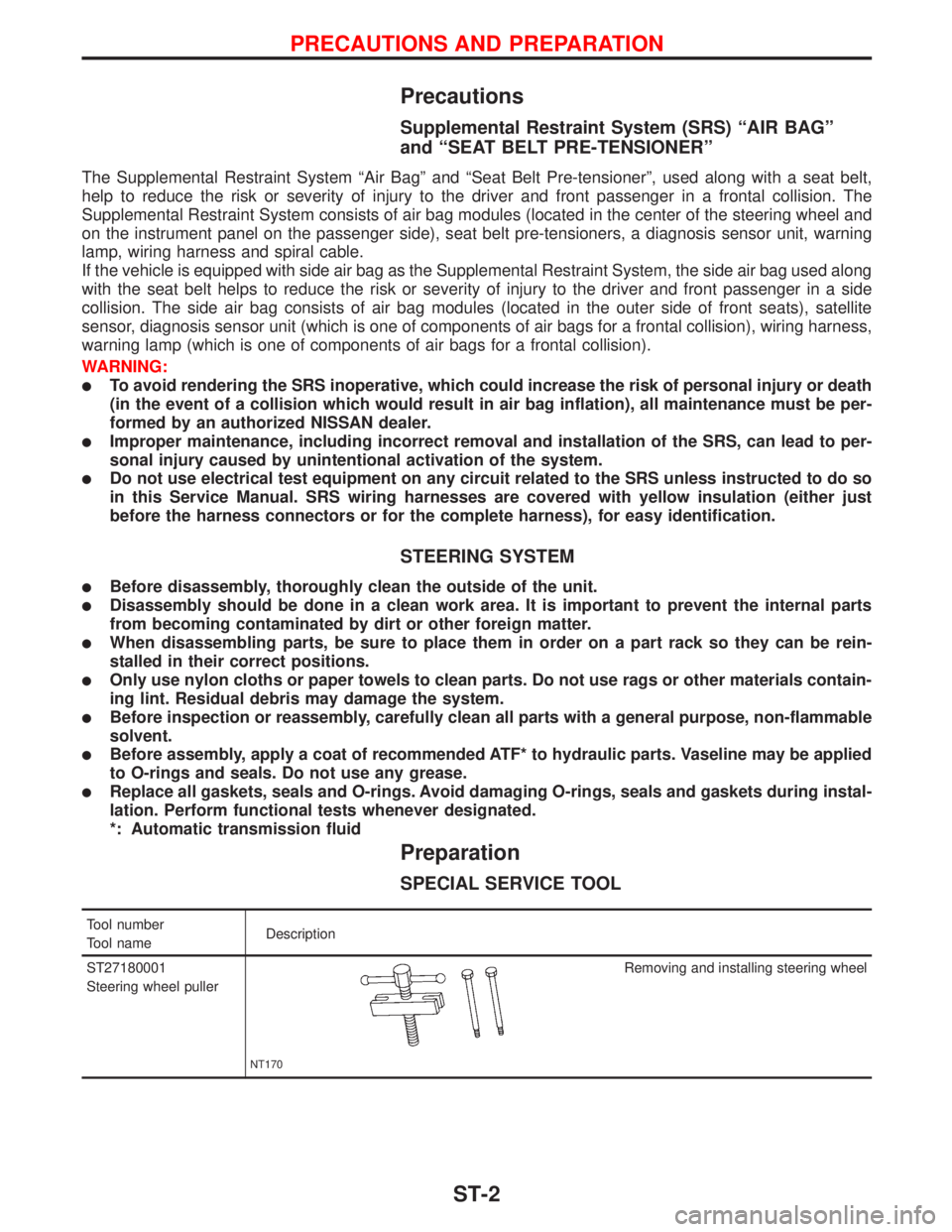
ST27180001
Steering wheel puller
NT170
Removing and installing steering wheel
PRECAUTIONS AND PREPARATION
ST-2
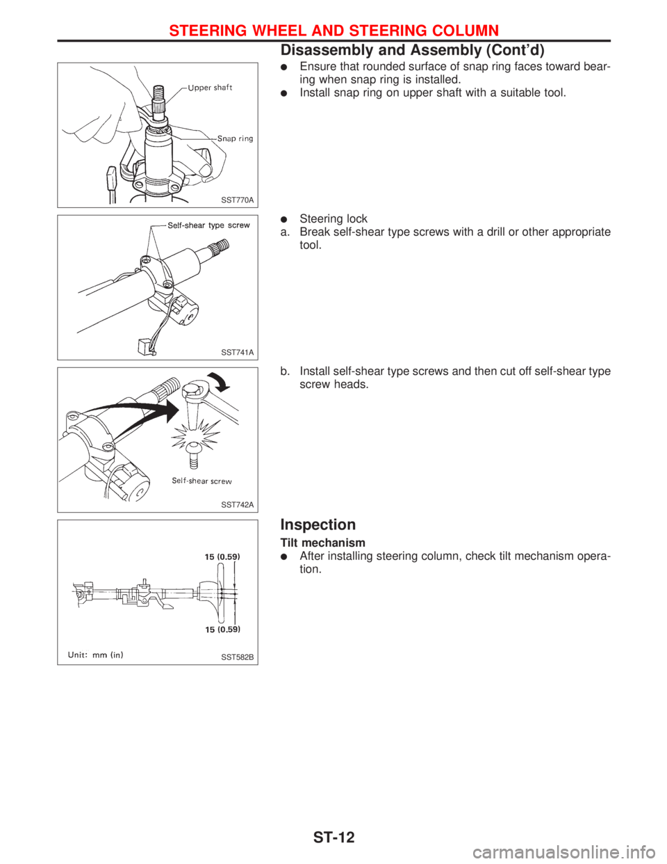
lEnsure that rounded surface of snap ring faces toward bear-
ing when snap ring is installed.
lInstall snap ring on upper shaft with a suitable tool.
lSteering lock
a. Break self-shear type screws with a drill or other appropriate
tool.
b. Install self-shear type screws and then cut off self-shear type
screw heads.
Inspection
Tilt mechanism
lAfter installing steering column, check tilt mechanism opera-
tion.
SST770A
SST741A
SST742A
SST582B
STEERING WHEEL AND STEERING COLUMN
Disassembly and Assembly (Cont'd)
ST-12