Page 1352 of 2267
YEL186C
BATTERY
OFF
1ST2NDCOMBINATION
SWITCH
(LIGHTING SWITCH)
FUSE BLOCK
(J/B): LHD models
: RHD models
: With daytime light system
: Without daytime light system
DAYTIME
LIGHT CONTROL
UNIT
FRONT
SPEAKER LHTWEETER
LH
REFER TO THE FOLLOWING
FUSE BLOCK - Junction Box (J/B)
FUSE BLOCK - Junction Box (J/B)AUDIO
FRONT
SPEAKER LH
AUDIO
Wiring Diagram—AUDIO—(Cont’d)
EL-220
Page 1362 of 2267
Wiring Diagram—SROOF—
YEL191C
BATTERYIGNITION SWITCH
ON or START
CIRCUIT
BREAKR-1POWER
WINDOW
RELAYFUSE
BLOCK
(J/B)
: LHD models
: RHD modelsRefer to
EL-POWER.
SUNROOF
SWITCH
OPENCLOSEOPEN
SUNROOF
MOTOR
REFER TO THE FOLLOWING
FUSE BLOCK - Junction Box (J/B)
FUSE BLOCK - Junction Box (J/B)
FUSE BLOCK - Junction Box (J/B)
FUSE BLOCK - Junction Box (J/B) CLOSE
ELECTRIC SUNROOF
EL-230
Page 1366 of 2267
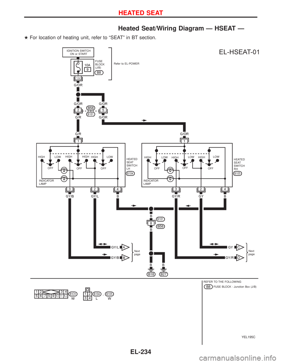
Heated Seat/Wiring Diagram—HSEAT—
�For location of heating unit, refer to“SEAT”in BT section.
YEL195C
IGNITION SWITCH
ON or START
FUSE
BLOCK
(J/B)Refer to EL-POWER
HIGH
OFFLOWHIGH
OFFHIGH
HIGH
OFFLOW
HEATED
SEAT
SWITCH
LHHIGH
OFFLOW
HIGH
OFFLOW
HIGH
OFFLOW
HEATED
SEAT
SWITCH
RH
INDICATOR
LAMPINDICATOR
LAMP
Next
pageNext
page
REFER TO THE FOLLOWING
FUSE BLOCK - Junction Box (J/B)
HEATED SEAT
EL-234
Page 1430 of 2267
Wiring Diagram—MULTI—
YEL207C IGNITION SWITCH
ON or STARTBATTERY
CIRCUIT
BREAKER-1FUSE
BLOCK
(J/B)Refer to EL-POWER
TIME
CONTROL
UNIT
KEY
SWITCH
INSERTED
WITHDRAWN
REFER TO THE FOLLOWING
FUSE BLOCK - Junction Box (J/B)
FUSE BLOCK - Junction Box (J/B)
FUSE BLOCK - Junction Box (J/B)
: This connector is not shown in“HARNESS LAYOUT”of EL section.
MULTI-REMOTE CONTROL SYSTEM
EL-298
Page 1475 of 2267
Wiring Diagram—NATS—
MODELS BEFORE VIN - P11U0548750 (Type-1)
YEL216C
BATTERY BATTERYIGNITION SWITCH
ON or START
FUSE
BLOCK
(J/B)Refer to EL-POWER.
NATS
SECURITY
INDICATORAUDIODONGLE
CONTROL UNIT: With gasoline engine
: With diesel engine
: With GA engine
: With SR engine or
QG engine
: RHD models
: Except
INJECTION
PUMPTIME
CONTROL
UNIT
REFER TO THE FOLLOWING
FUSE BLOCK - Junction Box (J/B)
FUSE BLOCK - Junction Box (J/B)
FUSE BLOCK - Junction Box (J/B)
FUSE BLOCK - Junction Box (J/B)
FUSE BLOCK - Junction Box (J/B)
NATS (Nissan Anti-Theft System)
EL-343
Page 1792 of 2267
Terminal Arrangement
YEL232C To time control unit
UP
Spare fuse Fuel pump relay
Front fog lamp relay
Rear window defogger relay Power window relay
To air bag harness
To room lamp harness :
To main harness:
Ignition relay
Circuit breaker-1
Blower relayTo main harness
To engine
room harness
: LHD models
: RHD models
To body harness
FUSE BLOCK — Junction Box (J/B)
Page 1806 of 2267
Sample/Wiring Diagram Ð EXAMPL Ð
lFor Description, refer to GI-13.
YGI001
Refer to optional splice. BATTERY
Preceding
page
RELAY
MOTOR
MOTOR
CONTROL
MODULE
A/T models
M/T models
.REFER TO THE FOLLOWINGM1,E103FUSE BLOCK -
Junction Box (J/B)
M2FUSE BLOCK -
Junction Box (J/B)
E127FUSE BLOCK -
Junction Box (J/B) POWER JOINT
CONNECTOR-1
SWITCHTo EL-
EXAMPL
Next page
To GI-
EXAMPL-04
DIODE
POSITION
APOSITION
BSIGNAL
GND GNDUNIT
HOW TO READ WIRING DIAGRAMS
GI-11
Page 1809 of 2267
 is diff")
Number Item Description
p19Current flow arrow
lArrow indicates electric current flow, especially where the direction of stan-
dard flow (vertically downward or horizontally from left to right) is difficult to
follow.
lA double arrow ªFÐ
Eº shows that current can flow in either direction depend-
ing on circuit operation.
p20System branchlThis shows that the system branches to another system identified by cell
code (section and system).
p21Page crossing
lThis arrow shows that the circuit continues to another page identified by cell
code.
lThe C will match with the C on another page within the system other than the
next or preceding pages.
p22Shielded linelThe line enclosed by broken line circle shows shield wire.
p23Component box in wave
linelThis shows that another part of the component is also shown on another
page (indicated by wave line) within the system.
p24Component namelThis shows the name of a component.
p25Connector number
lThis shows the connector number.
lThe letter shows which harness the connector is located in.
Example:M: main harness. For details and to locate the connector, refer to
EL section (ªMain Harnessº, ªHARNESS LAYOUTº). A coordinate grid is
included for complex harnesses to aid in locating connectors.
p26Ground (GND)lThe line spliced and grounded under wire color shows that ground line is
spliced at the grounded connector.
p27Ground (GND)lThis shows the ground connection.
p28Connector viewslThis area shows the connector faces of the components in the wiring diagram
on the page.
p29Common componentlConnectors enclosed in broken line show that these connectors belong to the
same component.
p30Connector colorlThis shows a code for the color of the connector. For code meaning, refer to
wire color codes, Number
p14of this chart.
p31Fusible link and fuse box
lThis shows the arrangement of fusible link(s) and fuse(s), used for connector
views of ªPOWER SUPPLY ROUTINGº in EL section.
The open square shows current flow in, and the shaded square shows cur-
rent flow out.
p32Reference arealThis shows that more information on the Super Multiple Junction (SMJ) and
Joint Connectors (J/C) exists on the foldout page.
HOW TO READ WIRING DIAGRAMS
Description (Cont'd)
GI-14

FUSE BLOCK
(J/B): LHD models
: RHD models
: With daytime light system
: Without daytime light system
DAYTIME
LIGHT CONTROL
UNIT
FRONT
SPE")

: LHD models
: RHD modelsRefer to
EL-POWER.
SUNROOF
SWITCH
OPENCLOSEOPEN
SUNROOF")
Refer to EL-POWER
TIME
CONTROL
UNIT
KEY
SWITCH
INSERTED
WITHDRAWN
REFER TO THE FOLLOWING
FUSE BLOC")

YEL216C
BATTERY BATTERYIGNITION SWITCH
ON or START
FUSE
BLOCK
(J/B)Refer to EL-POWER.
NATS
SECURITY
INDICATORAUDIODONGLE
CONTROL UNIT:")

