1999 NISSAN PRIMERA power steering
[x] Cancel search: power steeringPage 827 of 2267
IAt high engine speeds.
IWhen the engine coolant temperature becomes excessively high.
IWhen operating power steering during low engine speed or low vehicle speed.
IWhen engine speed is excessively low.
Fuel Cut Control (at no load & high engine
speed)
DESCRIPTIONNCEC0017Input/Output Signal ChartNCEC0017S01
Sensor Input Signal to ECMECM func-
tionActuator
Vehicle speed sensor or ABS actuator and
electric unit (control unit)Vehicle speed
Fuel cut
controlInjectors PNP switch Neutral position
Throttle position sensor Throttle position
Engine coolant temperature sensor Engine coolant temperature
Camshaft position sensor Engine speed
If the engine speed is above 3,950 rpm with no load, (for example, in Neutral and engine speed over 4,000
rpm) fuel will be cut off after some time. The exact time when the fuel is cut off varies based on engine speed.
Fuel cut will operate until the engine speed reaches 1,150 rpm, then fuel cut is cancelled.
NOTE:
This function is different from deceleration control listed under ªMultiport Fuel Injection (MFI) Systemº,
EC-SR-23.
Evaporative Emission System
DESCRIPTIONNCEC0018
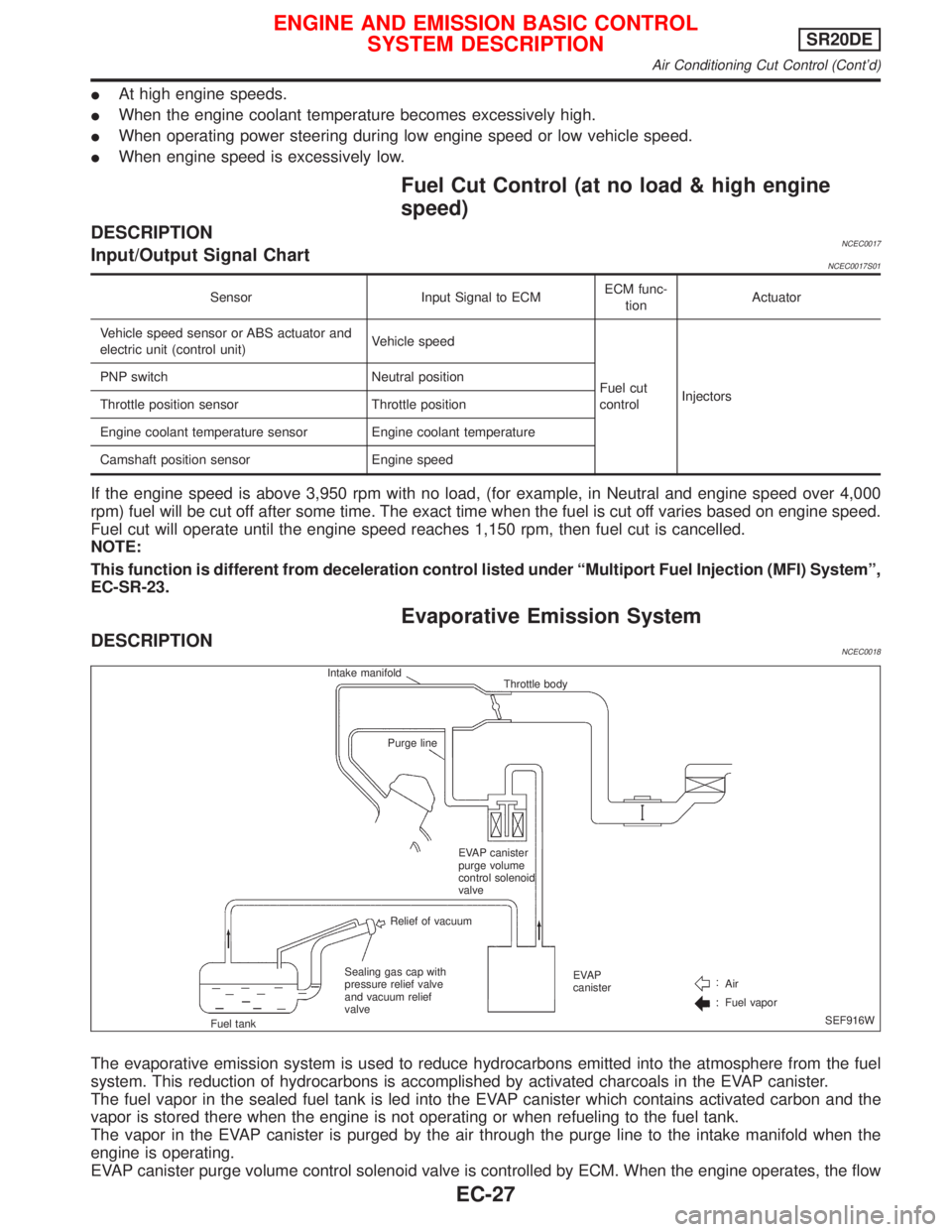
The evaporative emission system is used to reduce hydrocarbons emitted into the atmosphere from the fuel
system. This reduction of hydrocarbons is accomplished by activated charcoals in the EVAP canister.
The fuel vapor in the sealed fuel tank is led into the EVAP canister which contains activated carbon and the
vapor is stored there when the engine is not operating or when refueling to the fuel tank.
The vapor in the EVAP canister is purged by the air through the purge line to the intake manifold when the
engine is operating.
EVAP canister purge volume control solenoid valve is controlled by ECM. When the engine operates, the flow
Intake manifold
Throttle body
Purge line
EVAP canister
purge volume
control solenoid
valve
Relief of vacuum
Sealing gas cap with
pressure relief valve
and vacuum relief
valve
Fuel tankAir
Fuel vapor EVAP
canister
SEF916W
ENGINE AND EMISSION BASIC CONTROL
SYSTEM DESCRIPTIONSR20DE
Air Conditioning Cut Control (Cont'd)
EC-27
Page 829 of 2267
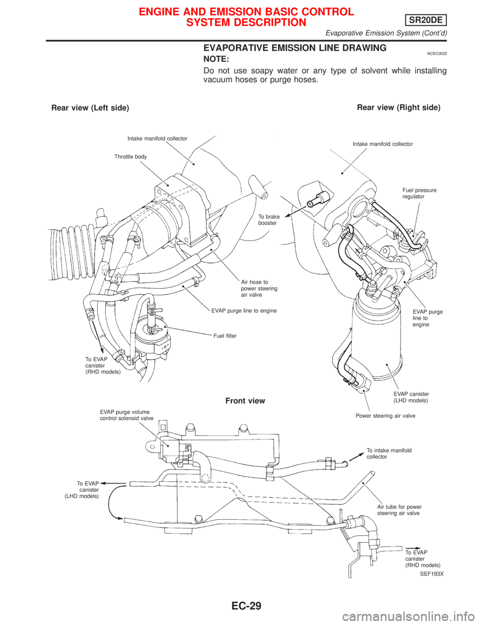
EVAPORATIVE EMISSION LINE DRAWINGNCEC0020NOTE:
Do not use soapy water or any type of solvent while installing
vacuum hoses or purge hoses.
SEF193X Intake manifold collector
Throttle body
Rear view (Left side)Rear view (Right side)
Intake manifold collector
Fuel pressure
regulator
To brake
booster
Air hose to
power steering
air valve
EVAP purge line to engine
Fuel filter
To EVAP
canister
(RHD models)
EVAP purge volume
control solenoid valve
To EVAP
canister
(LHD models)
Front view
EVAP purge
line to
engine
EVAP canister
(LHD models)
Power steering air valve
To intake manifold
collector
Air tube for power
steering air valve
To EVAP
canister
(RHD models)
ENGINE AND EMISSION BASIC CONTROL
SYSTEM DESCRIPTIONSR20DE
Evaporative Emission System (Cont'd)
EC-29
Page 869 of 2267
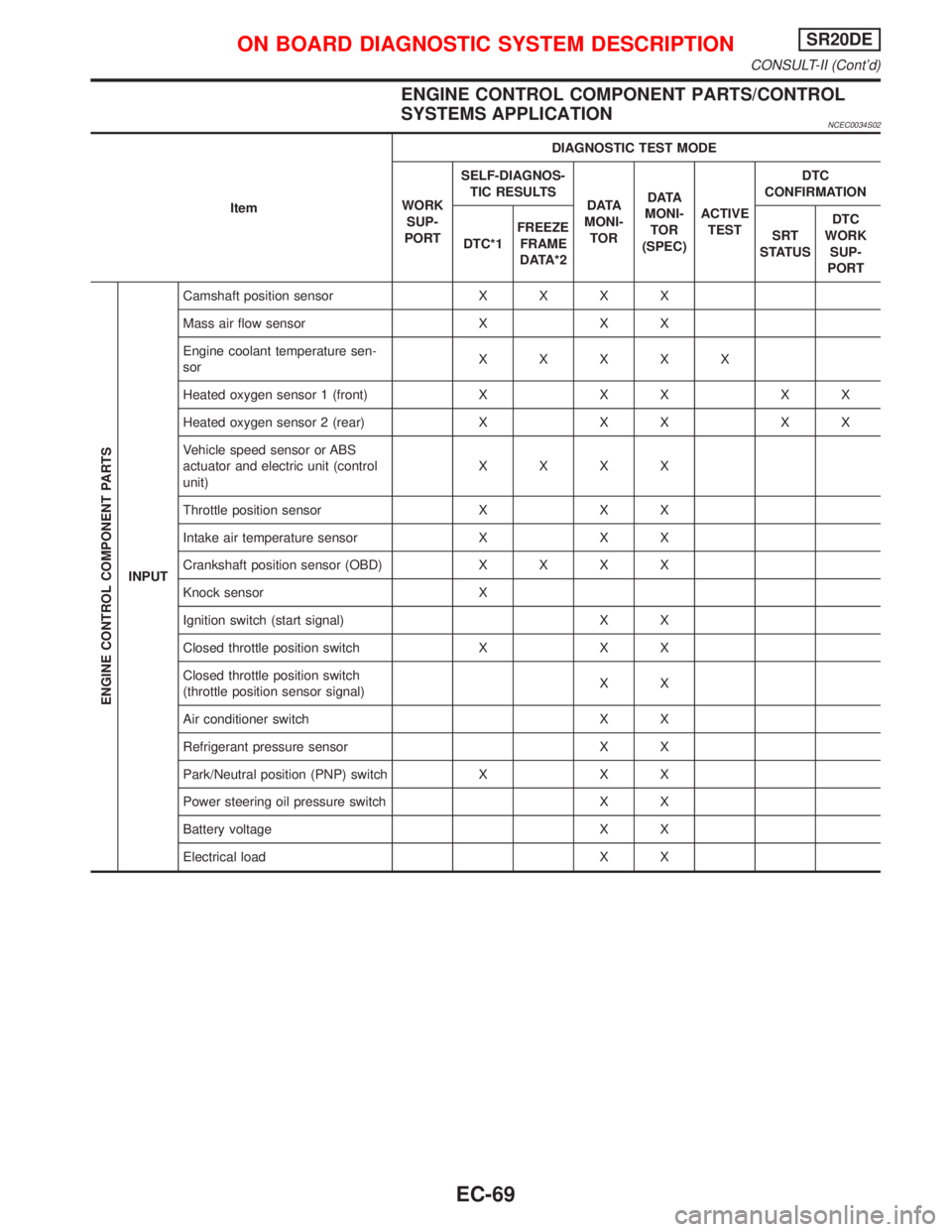
ENGINE CONTROL COMPONENT PARTS/CONTROL
SYSTEMS APPLICATION
NCEC0034S02
ItemDIAGNOSTIC TEST MODE
WORK
SUP-
PORTSELF-DIAGNOS-
TIC RESULTS
D ATA
MONI-
TORD ATA
MONI-
TOR
(SPEC)ACTIVE
TESTDTC
CONFIRMATION
DTC*1FREEZE
FRAME
DATA*2SRT
STATUSDTC
WORK
SUP-
PORT
ENGINE CONTROL COMPONENT PARTS
INPUTCamshaft position sensorXXXX
Mass air flow sensor X X X
Engine coolant temperature sen-
sorXXXXX
Heated oxygen sensor 1 (front) X X X X X
Heated oxygen sensor 2 (rear) X X X X X
Vehicle speed sensor or ABS
actuator and electric unit (control
unit)XXXX
Throttle position sensor X X X
Intake air temperature sensor X X X
Crankshaft position sensor (OBD)XXXX
Knock sensor X
Ignition switch (start signal) X X
Closed throttle position switch X X X
Closed throttle position switch
(throttle position sensor signal)XX
Air conditioner switch X X
Refrigerant pressure sensor X X
Park/Neutral position (PNP) switch X X X
Power steering oil pressure switch X X
Battery voltage X X
Electrical load X X
ON BOARD DIAGNOSTIC SYSTEM DESCRIPTIONSR20DE
CONSULT-II (Cont'd)
EC-69
Page 873 of 2267
![NISSAN PRIMERA 1999 Electronic Repair Manual Monitored item [Unit]ECM
input
signalsMain
signalsDescription Remarks
AIR COND SIG
[ON/OFF]qqIIndicates [ON/OFF] condition of the air
conditioner switch as determined by the
air conditioning signal.
P NISSAN PRIMERA 1999 Electronic Repair Manual Monitored item [Unit]ECM
input
signalsMain
signalsDescription Remarks
AIR COND SIG
[ON/OFF]qqIIndicates [ON/OFF] condition of the air
conditioner switch as determined by the
air conditioning signal.
P](/manual-img/5/57377/w960_57377-872.png)
Monitored item [Unit]ECM
input
signalsMain
signalsDescription Remarks
AIR COND SIG
[ON/OFF]qqIIndicates [ON/OFF] condition of the air
conditioner switch as determined by the
air conditioning signal.
P/N POSI SW
[ON/OFF]qqIIndicates [ON/OFF] condition from the
PNP switch signal.
PW/ST SIGNAL
[ON/OFF]qqIIndicates [ON/OFF] condition of the
power steering oil pressure switch deter-
mined by the power steering oil pressure
switch signal.
LOAD SIGNAL
[ON/OFF]qqIIndicates [ON/OFF] condition from the
electrical load signal and/or lighting
switch.
ON ... rear defogger is operating and/or
lighting switch is on.
OFF ... rear defogger is not operating
and lighting switch is not on.
IGNITION SW
[ON/OFF]qIIndicates [ON/OFF] condition from igni-
tion switch.
HEATER FAN SW
[ON/OFF]qIIndicates [ON/OFF] condition from the
heater fan switch.
INJ PULSE -B1
[msec]qIIndicates the actual fuel injection pulse
width compensated by ECM according to
the input signals.IWhen the engine is stopped, a cer-
tain computed value is indicated.
B/FUEL SCHDL
[msec]IªBase fuel scheduleº indicates the fuel
injection pulse width programmed into
ECM, prior to any learned on board cor-
rection.
IGN TIMING [BTDC]qIIndicates the ignition timing computed by
ECM according to the input signals.
IACV-AAC/V [step]qIIndicates the IACV-AAC valve control
value computed by ECM according to
the input signals.
A/F ALPHA -B1 [%]qIIndicates the mean value of the air-fuel
ratio feedback correction factor per
cycle.IWhen the engine is stopped, a cer-
tain value is indicated.
IThis data also includes the data for
the air-fuel ratio learning control.
AIR COND RLY
[ON/OFF]qIIndicates the air conditioner relay control
condition determined by ECM according
to the input signals.
FUEL PUMP RLY
[ON/OFF]qIIndicates the fuel pump relay control
condition determined by ECM according
to the input signals.
COOLING FAN
[HI/LOW/OFF]qIIndicates the control condition of the
cooling fan determined by ECM accord-
ing to the input signals.
HI ... High speed operation
LOW ... Low speed operation
OFF ... Stop
HO2S1 HTR (B1)
[ON/OFF]IIndicates [ON/OFF] condition of heated
oxygen sensor 1 (front) heater deter-
mined by ECM according to the input
signals.
ON BOARD DIAGNOSTIC SYSTEM DESCRIPTIONSR20DE
CONSULT-II (Cont'd)
EC-73
Page 895 of 2267
SYMPTOM
Reference
page
HARD/NO START/RESTART (EXCP. HA)
ENGINE STALL
HESITATION/SURGING/FLAT SPOT
SPARK KNOCK/DETONATION
LACK OF POWER/POOR ACCELERATION
HIGH IDLE/LOW IDLE
ROUGH IDLE/HUNTING
IDLING VIBRATION
SLOW/NO RETURN TO IDLE
OVERHEATS/WATER TEMPERATURE HIGH
EXCESSIVE FUEL CONSUMPTION
EXCESSIVE OIL CONSUMPTION
BATTERY DEAD (UNDER CHARGE)
Warranty symptom code AA AB AC AD AE AF AG AH AJ AK AL AM HA
Camshaft position sensor circuit22333 33 3EC-SR-
239
Mass air flow sensor circuit11222 22 2EC-SR-
120
Heated oxygen sensor 1 (front)
circuit1232 22 2EC-SR-
144, 150
Engine coolant temperature sen-
sor circuit112323223 2EC-SR-
132
Throttle position sensor circuit 1 222222 2EC-SR-
137
Incorrect throttle position sensor
adjustment31 11111 1EC-SR-84
Vehicle speed sensor circuit or
ABS actuator and electric unit
(control unit) circuit23 3 3EC-SR-
255
Knock sensor circuit 2 3EC-SR-
230
ECM 22333333333EC-SR-
277, 93
Start signal circuit 2EC-SR-
312
PNP switch circuit 3 3 3 3 3EC-SR-
298
Power steering oil pressure
switch circuit233EC-SR-
322
Electrical load signal circuit 3 3EC-SR-
326
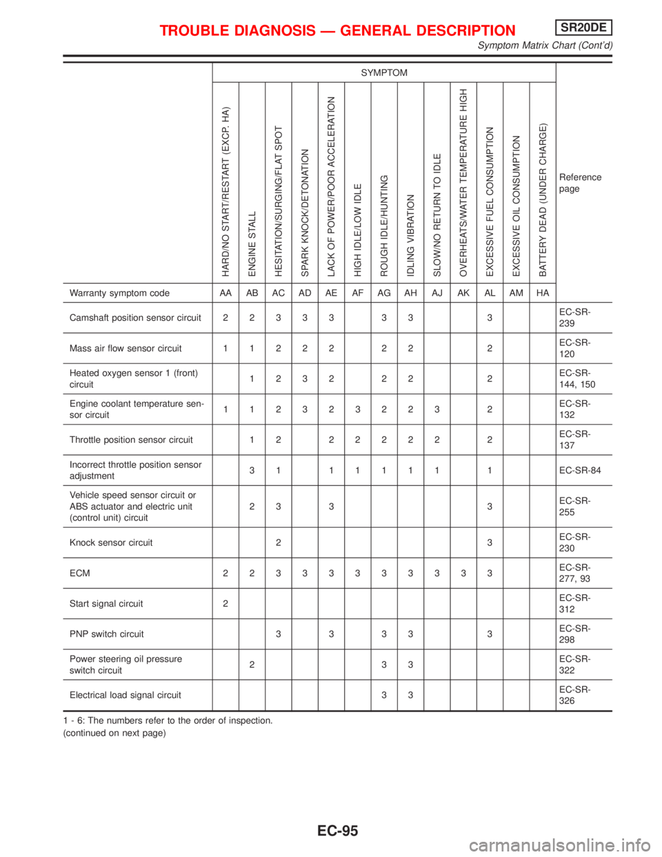
1 - 6: The numbers refer to the order of inspection.
(continued on next page)
TROUBLE DIAGNOSIS Ð GENERAL DESCRIPTIONSR20DE
Symptom Matrix Chart (Cont'd)
EC-95
Page 906 of 2267
![NISSAN PRIMERA 1999 Electronic Repair Manual TERMI-
NAL
NO.WIRE
COLORITEM CONDITION DATA (DC Voltage)
36*1 G Ignition check[Engine is running]
IWarm-up condition
IIdle speedApproximately 13V
SEF998V
[Engine is running]
IEngine speed is 2,000 rpm NISSAN PRIMERA 1999 Electronic Repair Manual TERMI-
NAL
NO.WIRE
COLORITEM CONDITION DATA (DC Voltage)
36*1 G Ignition check[Engine is running]
IWarm-up condition
IIdle speedApproximately 13V
SEF998V
[Engine is running]
IEngine speed is 2,000 rpm](/manual-img/5/57377/w960_57377-905.png)
TERMI-
NAL
NO.WIRE
COLORITEM CONDITION DATA (DC Voltage)
36*1 G Ignition check[Engine is running]
IWarm-up condition
IIdle speedApproximately 13V
SEF998V
[Engine is running]
IEngine speed is 2,000 rpmApproximately 12V
SEF999V
40 YThrottle position switch
(Closed position)[Engine is running]
IAccelerator pedal releasedBATTERY VOLTAGE
(11 - 14V)
[Ignition switch ªONº]
IAccelerator pedal depressedApproximately 0V
41 B/Y Start signal[Ignition switch ªONº]Approximately 0V
[Ignition switch ªSTARTº]9 - 12V
42 G/OR PNP switch[Ignition switch ªONº]
IGear position is ªNeutral positionº (M/T mod-
els)
IGear position is ªPº or ªNº (CVT models)Approximately 0V
[Ignition switch ªONº]
IExcept the above gear positionBATTERY VOLTAGE
(11 - 14V)
43 B/R Ignition switch[Ignition switch ªOFFº]0V
[Ignition switch ªONº]BATTERY VOLTAGE
(11 - 14V)
44 Ð Air conditioner switch[Engine is running]
IBoth air conditioner switch and blower switch
are ªONº (Compressor operates)Approximately 0V
[Engine is running]
IAir conditioner switch is ªOFFºApproximately 5V
46 PU/WPower steering oil pres-
sure switch[Engine is running]
ISteering wheel is fully turnedApproximately 0V
[Engine is running]
ISteering wheel is not turnedApproximately 5V
48 B ECM ground[Engine is running]
IIdle speedEngine ground
(Probe this terminal with (þ)
tester probe when measuring)
50 R Electric load signal[Engine is running]
IHeadlamp switch or rear window defogger
switch is ªONºBATTERY VOLTAGE
(11 - 14V)
*1: If so equipped
TROUBLE DIAGNOSIS Ð GENERAL DESCRIPTIONSR20DE
ECM Terminals and Reference Value (Cont'd)
EC-106
Page 1063 of 2267
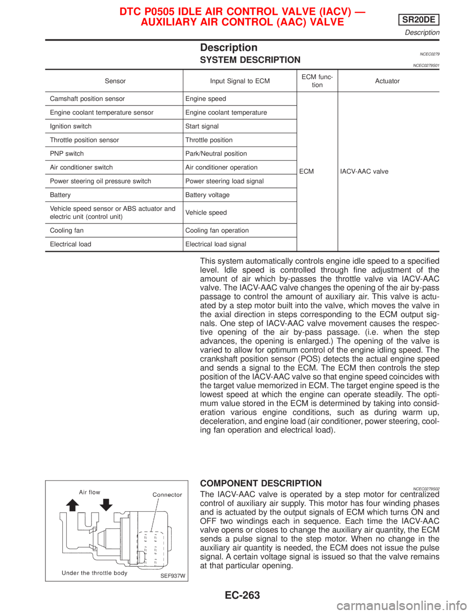
DescriptionNCEC0279SYSTEM DESCRIPTIONNCEC0279S01
Sensor Input Signal to ECMECM func-
tionActuator
Camshaft position sensor Engine speed
ECM IACV-AAC valve Engine coolant temperature sensor Engine coolant temperature
Ignition switch Start signal
Throttle position sensor Throttle position
PNP switch Park/Neutral position
Air conditioner switch Air conditioner operation
Power steering oil pressure switch Power steering load signal
Battery Battery voltage
Vehicle speed sensor or ABS actuator and
electric unit (control unit)Vehicle speed
Cooling fan Cooling fan operation
Electrical load Electrical load signal
This system automatically controls engine idle speed to a specified
level. Idle speed is controlled through fine adjustment of the
amount of air which by-passes the throttle valve via IACV-AAC
valve. The IACV-AAC valve changes the opening of the air by-pass
passage to control the amount of auxiliary air. This valve is actu-
ated by a step motor built into the valve, which moves the valve in
the axial direction in steps corresponding to the ECM output sig-
nals. One step of IACV-AAC valve movement causes the respec-
tive opening of the air by-pass passage. (i.e. when the step
advances, the opening is enlarged.) The opening of the valve is
varied to allow for optimum control of the engine idling speed. The
crankshaft position sensor (POS) detects the actual engine speed
and sends a signal to the ECM. The ECM then controls the step
position of the IACV-AAC valve so that engine speed coincides with
the target value memorized in ECM. The target engine speed is the
lowest speed at which the engine can operate steadily. The opti-
mum value stored in the ECM is determined by taking into consid-
eration various engine conditions, such as during warm up,
deceleration, and engine load (air conditioner, power steering, cool-
ing fan operation and electrical load).
COMPONENT DESCRIPTIONNCEC0279S02The IACV-AAC valve is operated by a step motor for centralized
control of auxiliary air supply. This motor has four winding phases
and is actuated by the output signals of ECM which turns ON and
OFF two windings each in sequence. Each time the IACV-AAC
valve opens or closes to change the auxiliary air quantity, the ECM
sends a pulse signal to the step motor. When no change in the
auxiliary air quantity is needed, the ECM does not issue the pulse
signal. A certain voltage signal is issued so that the valve remains
at that particular opening.
SEF937W
DTC P0505 IDLE AIR CONTROL VALVE (IACV) Ð
AUXILIARY AIR CONTROL (AAC) VALVESR20DE
Description
EC-263
Page 1067 of 2267
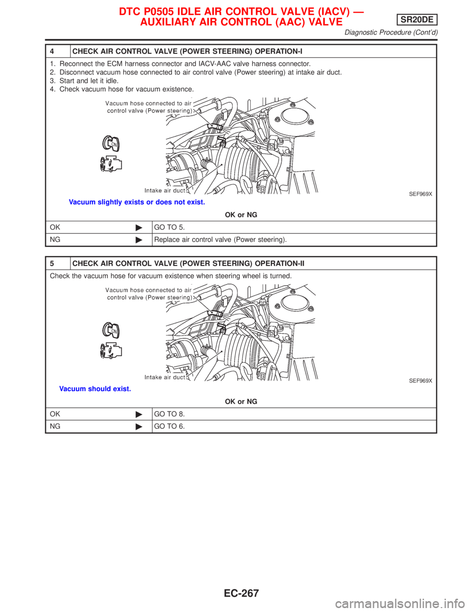
4 CHECK AIR CONTROL VALVE (POWER STEERING) OPERATION-I
1. Reconnect the ECM harness connector and IACV-AAC valve harness connector.
2. Disconnect vacuum hose connected to air control valve (Power steering) at intake air duct.
3. Start and let it idle.
4. Check vacuum hose for vacuum existence.
SEF969X
Vacuum slightly exists or does not exist.
OK or NG
OK©GO TO 5.
NG©Replace air control valve (Power steering).
5 CHECK AIR CONTROL VALVE (POWER STEERING) OPERATION-II
Check the vacuum hose for vacuum existence when steering wheel is turned.
SEF969X
Vacuum should exist.
OK or NG
OK©GO TO 8.
NG©GO TO 6.
DTC P0505 IDLE AIR CONTROL VALVE (IACV) Ð
AUXILIARY AIR CONTROL (AAC) VALVESR20DE
Diagnostic Procedure (Cont'd)
EC-267