1999 NISSAN PRIMERA power steering
[x] Cancel search: power steeringPage 788 of 2267
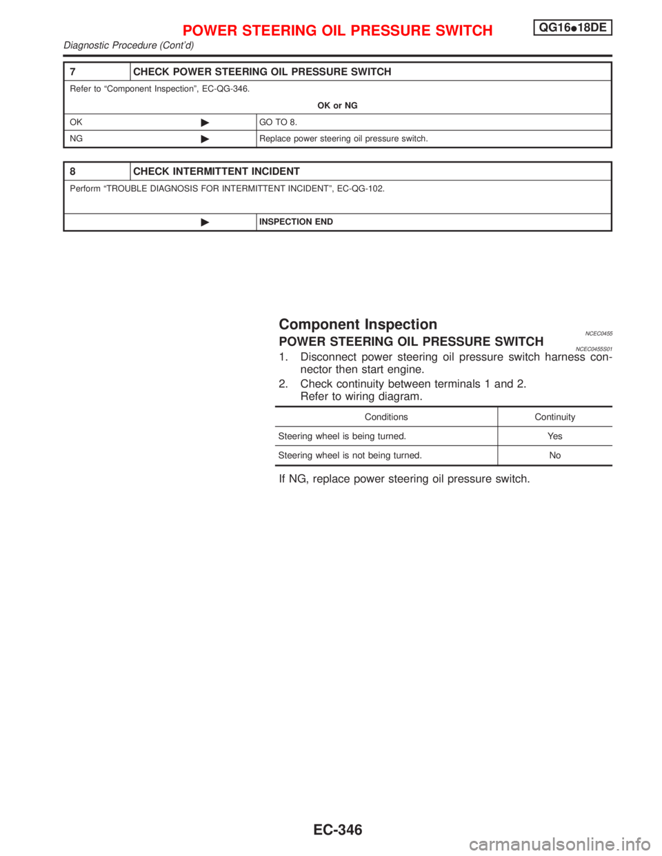
7 CHECK POWER STEERING OIL PRESSURE SWITCH
Refer to ªComponent Inspectionº, EC-QG-346.
OK or NG
OK©GO TO 8.
NG©Replace power steering oil pressure switch.
8 CHECK INTERMITTENT INCIDENT
Perform ªTROUBLE DIAGNOSIS FOR INTERMITTENT INCIDENTº, EC-QG-102.
©INSPECTION END
Component InspectionNCEC0455POWER STEERING OIL PRESSURE SWITCHNCEC0455S011. Disconnect power steering oil pressure switch harness con-
nector then start engine.
2. Check continuity between terminals 1 and 2.
Refer to wiring diagram.
Conditions Continuity
Steering wheel is being turned. Yes
Steering wheel is not being turned. No
If NG, replace power steering oil pressure switch.
POWER STEERING OIL PRESSURE SWITCHQG16I18DE
Diagnostic Procedure (Cont'd)
EC-346
Page 805 of 2267
CONSULT-II Reference Value in Data Monitor
Mode ........................................................................306
ECM Terminals and Reference Value .....................306
Wiring Diagram ........................................................308
Diagnostic Procedure ..............................................309
Component Inspection .............................................310
START SIGNAL...........................................................312
CONSULT-II Reference Value in Data Monitor
Mode ........................................................................312
ECM Terminals and Reference Value .....................312
Wiring Diagram ........................................................313
Diagnostic Procedure ..............................................314
FUEL PUMP.................................................................316
System Description ..................................................316
Component Description ...........................................316
CONSULT-II Reference Value in Data Monitor
Mode ........................................................................316
ECM Terminals and Reference Value .....................316
Wiring Diagram ........................................................317
Diagnostic Procedure ..............................................318
Component Inspection .............................................320
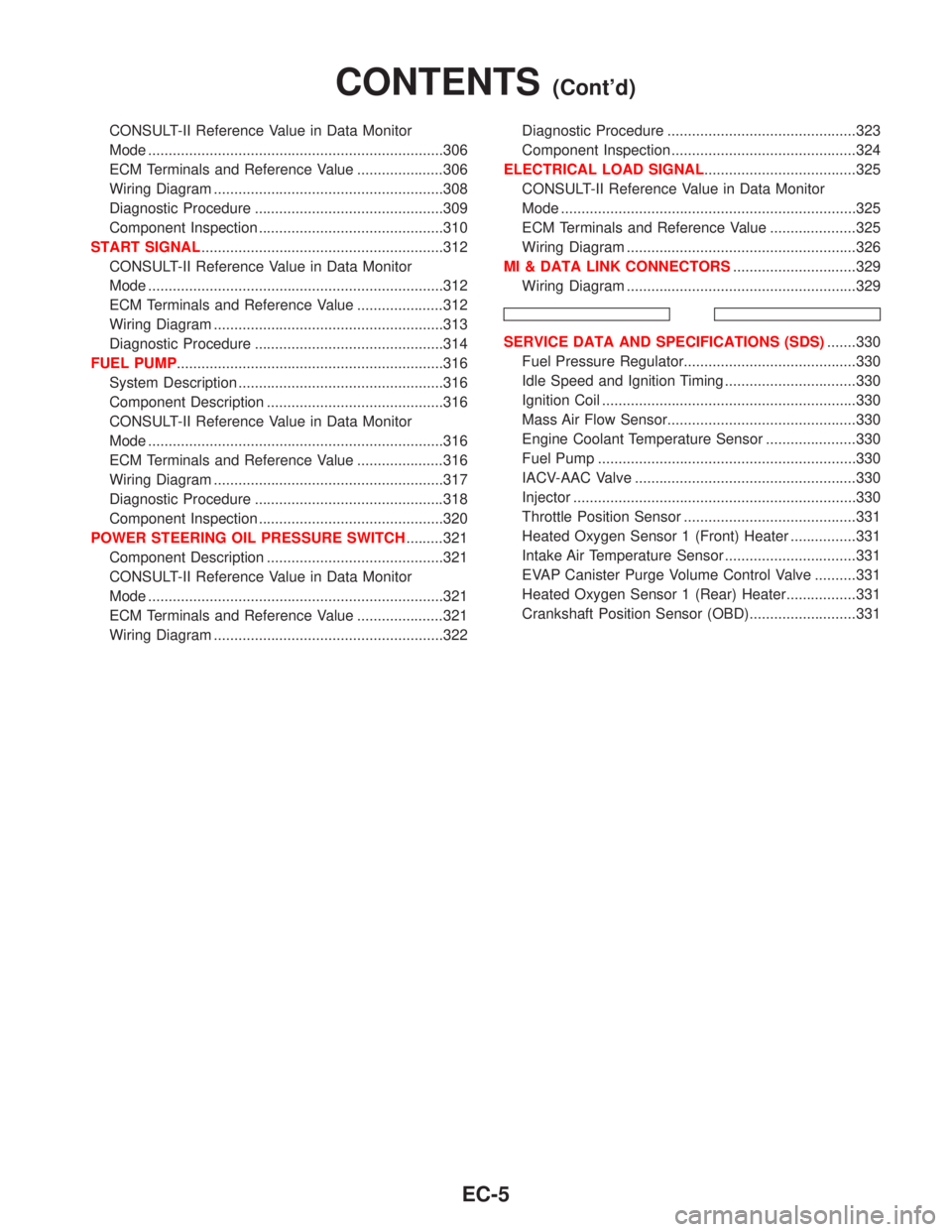
POWER STEERING OIL PRESSURE SWITCH.........321
Component Description ...........................................321
CONSULT-II Reference Value in Data Monitor
Mode ........................................................................321
ECM Terminals and Reference Value .....................321
Wiring Diagram ........................................................322Diagnostic Procedure ..............................................323
Component Inspection .............................................324
ELECTRICAL LOAD SIGNAL.....................................325
CONSULT-II Reference Value in Data Monitor
Mode ........................................................................325
ECM Terminals and Reference Value .....................325
Wiring Diagram ........................................................326
MI & DATA LINK CONNECTORS..............................329
Wiring Diagram ........................................................329
SERVICE DATA AND SPECIFICATIONS (SDS).......330
Fuel Pressure Regulator..........................................330
Idle Speed and Ignition Timing ................................330
Ignition Coil ..............................................................330
Mass Air Flow Sensor..............................................330
Engine Coolant Temperature Sensor ......................330
Fuel Pump ...............................................................330
IACV-AAC Valve ......................................................330
Injector .....................................................................330
Throttle Position Sensor ..........................................331
Heated Oxygen Sensor 1 (Front) Heater ................331
Intake Air Temperature Sensor ................................331
EVAP Canister Purge Volume Control Valve ..........331
Heated Oxygen Sensor 1 (Rear) Heater.................331
Crankshaft Position Sensor (OBD)..........................331
CONTENTS(Cont'd)
EC-5
Page 815 of 2267
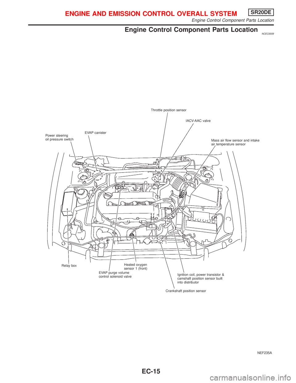
Engine Control Component Parts LocationNCEC0009
NEF235A Throttle position sensor
IACV-AAC valve
Mass air flow sensor and intake
air temperature sensor
Ignition coil, power transistor &
camshaft position sensor built
into distributor
Crankshaft position sensor Relay box
EVAP purge volume
control solenoid valveHeated oxygen
sensor 1 (front) EVAP canister
Power steering
oil pressure switch
ENGINE AND EMISSION CONTROL OVERALL SYSTEMSR20DE
Engine Control Component Parts Location
EC-15
Page 817 of 2267
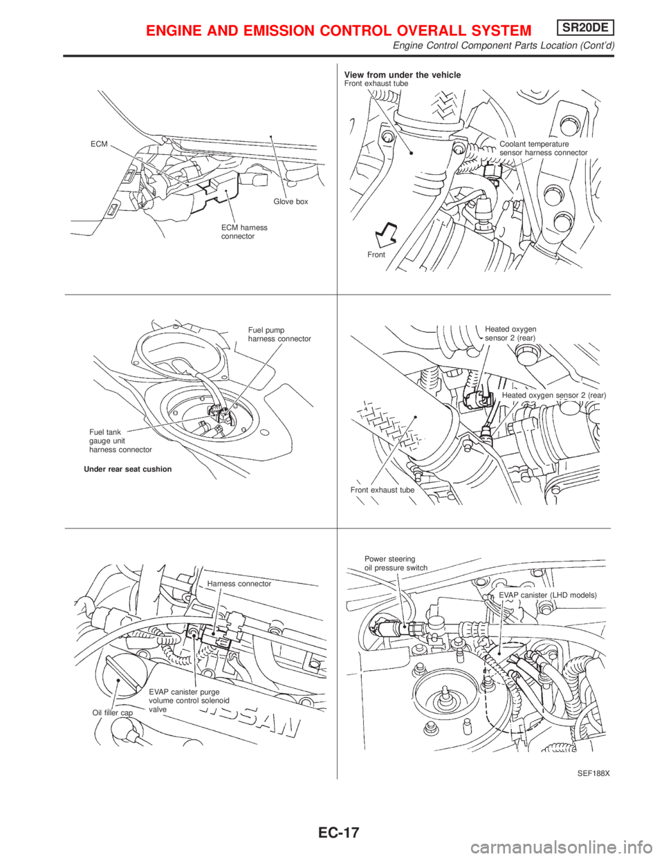
SEF188X ECM
ECM harness
connectorGlove box
View from under the vehicleFront exhaust tube
Coolant temperature
sensor harness connector
Front
Fuel pump
harness connector
Fuel tank
gauge unit
harness connector
Under rear seat cushion
Front exhaust tubeHeated oxygen
sensor 2 (rear)
Heated oxygen sensor 2 (rear)
Harness connector
EVAP canister purge
volume control solenoid
valve
Oil filler capPower steering
oil pressure switch
EVAP canister (LHD models)
ENGINE AND EMISSION CONTROL OVERALL SYSTEMSR20DE
Engine Control Component Parts Location (Cont'd)
EC-17
Page 821 of 2267
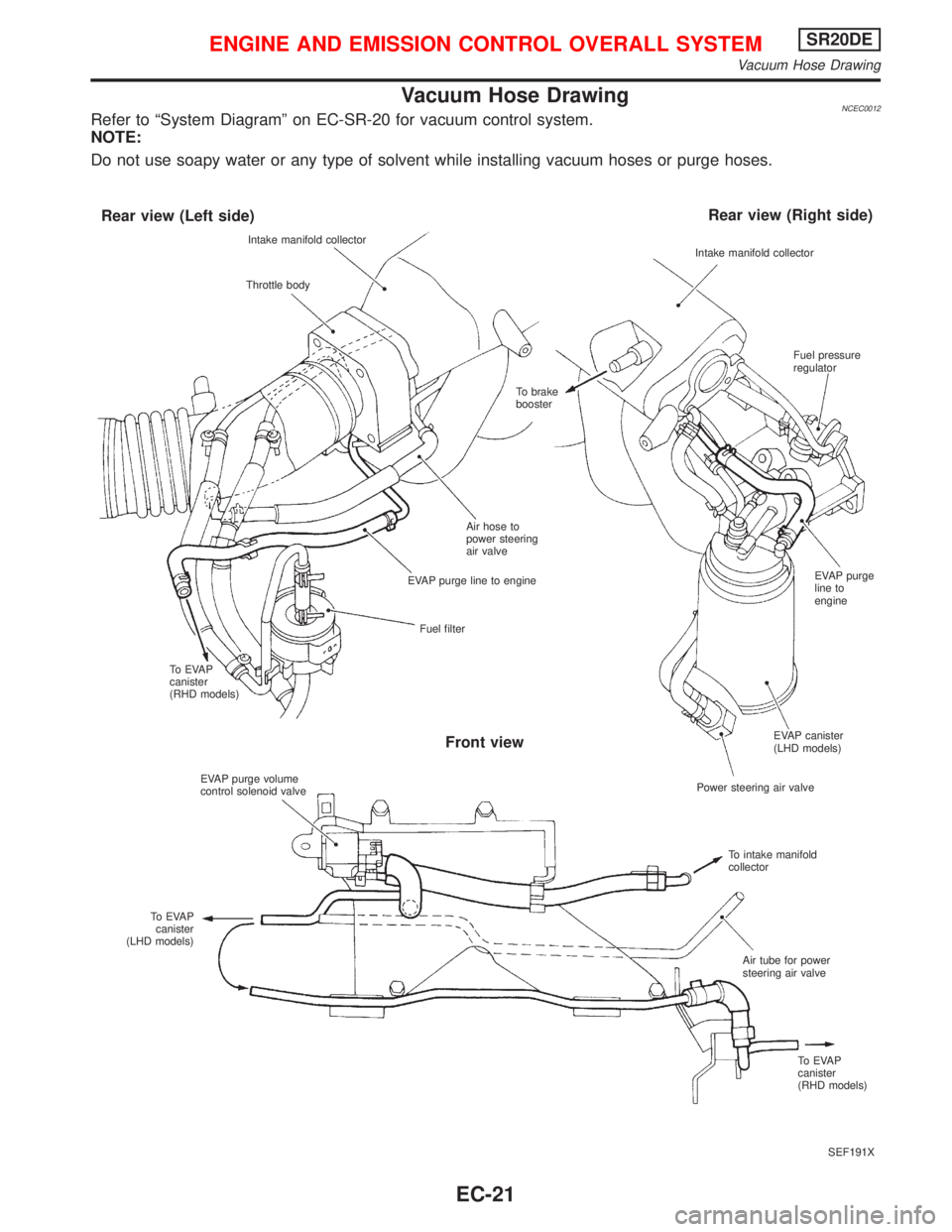
Vacuum Hose DrawingNCEC0012Refer to ªSystem Diagramº on EC-SR-20 for vacuum control system.
NOTE:
Do not use soapy water or any type of solvent while installing vacuum hoses or purge hoses.
SEF191X Intake manifold collector
Throttle body
Rear view (Left side)Rear view (Right side)
Intake manifold collector
Fuel pressure
regulator
To brake
booster
Air hose to
power steering
air valve
EVAP purge line to engine
Fuel filter
To EVAP
canister
(RHD models)
EVAP purge volume
control solenoid valve
To EVAP
canister
(LHD models)
Front view
EVAP purge
line to
engine
EVAP canister
(LHD models)
Power steering air valve
To intake manifold
collector
Air tube for power
steering air valve
To EVAP
canister
(RHD models)
ENGINE AND EMISSION CONTROL OVERALL SYSTEMSR20DE
Vacuum Hose Drawing
EC-21
Page 822 of 2267
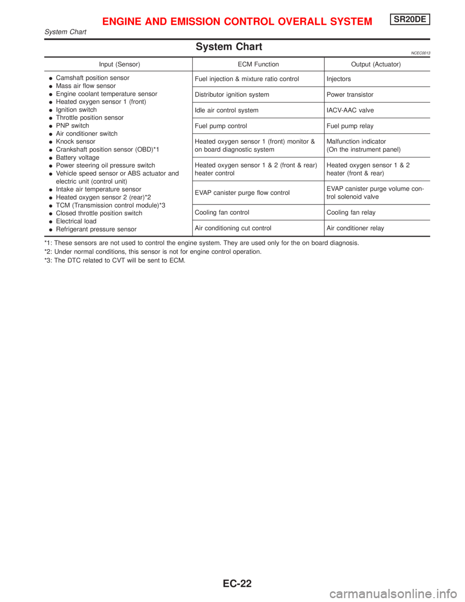
System ChartNCEC0013
Input (Sensor) ECM Function Output (Actuator)
ICamshaft position sensor
IMass air flow sensor
IEngine coolant temperature sensor
IHeated oxygen sensor 1 (front)
IIgnition switch
IThrottle position sensor
IPNP switch
IAir conditioner switch
IKnock sensor
ICrankshaft position sensor (OBD)*1
IBattery voltage
IPower steering oil pressure switch
IVehicle speed sensor or ABS actuator and
electric unit (control unit)
IIntake air temperature sensor
IHeated oxygen sensor 2 (rear)*2
ITCM (Transmission control module)*3
IClosed throttle position switch
IElectrical load
IRefrigerant pressure sensorFuel injection & mixture ratio control Injectors
Distributor ignition system Power transistor
Idle air control system IACV-AAC valve
Fuel pump control Fuel pump relay
Heated oxygen sensor 1 (front) monitor &
on board diagnostic systemMalfunction indicator
(On the instrument panel)
Heated oxygen sensor1&2(front & rear)
heater controlHeated oxygen sensor1&2
heater (front & rear)
EVAP canister purge flow controlEVAP canister purge volume con-
trol solenoid valve
Cooling fan control Cooling fan relay
Air conditioning cut control Air conditioner relay
*1: These sensors are not used to control the engine system. They are used only for the on board diagnosis.
*2: Under normal conditions, this sensor is not for engine control operation.
*3: The DTC related to CVT will be sent to ECM.
ENGINE AND EMISSION CONTROL OVERALL SYSTEMSR20DE
System Chart
EC-22
Page 823 of 2267
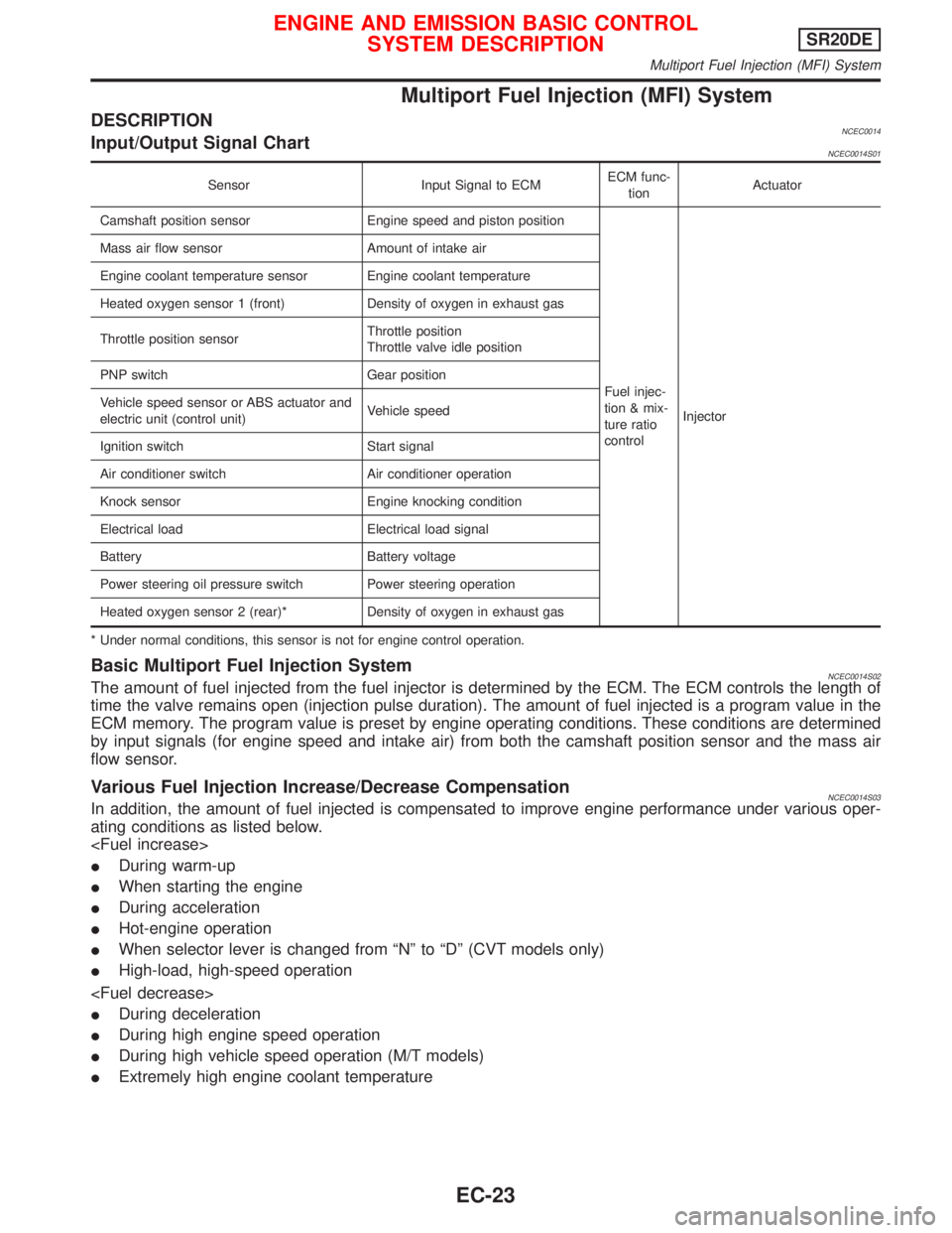
Multiport Fuel Injection (MFI) System
DESCRIPTIONNCEC0014Input/Output Signal ChartNCEC0014S01
Sensor Input Signal to ECMECM func-
tionActuator
Camshaft position sensor Engine speed and piston position
Fuel injec-
tion & mix-
ture ratio
controlInjector Mass air flow sensor Amount of intake air
Engine coolant temperature sensor Engine coolant temperature
Heated oxygen sensor 1 (front) Density of oxygen in exhaust gas
Throttle position sensorThrottle position
Throttle valve idle position
PNP switch Gear position
Vehicle speed sensor or ABS actuator and
electric unit (control unit)Vehicle speed
Ignition switch Start signal
Air conditioner switch Air conditioner operation
Knock sensor Engine knocking condition
Electrical load Electrical load signal
Battery Battery voltage
Power steering oil pressure switch Power steering operation
Heated oxygen sensor 2 (rear)* Density of oxygen in exhaust gas
* Under normal conditions, this sensor is not for engine control operation.
Basic Multiport Fuel Injection SystemNCEC0014S02The amount of fuel injected from the fuel injector is determined by the ECM. The ECM controls the length of
time the valve remains open (injection pulse duration). The amount of fuel injected is a program value in the
ECM memory. The program value is preset by engine operating conditions. These conditions are determined
by input signals (for engine speed and intake air) from both the camshaft position sensor and the mass air
flow sensor.
Various Fuel Injection Increase/Decrease CompensationNCEC0014S03In addition, the amount of fuel injected is compensated to improve engine performance under various oper-
ating conditions as listed below.
IDuring warm-up
IWhen starting the engine
IDuring acceleration
IHot-engine operation
IWhen selector lever is changed from ªNº to ªDº (CVT models only)
IHigh-load, high-speed operation
IDuring deceleration
IDuring high engine speed operation
IDuring high vehicle speed operation (M/T models)
IExtremely high engine coolant temperature
ENGINE AND EMISSION BASIC CONTROL
SYSTEM DESCRIPTIONSR20DE
Multiport Fuel Injection (MFI) System
EC-23
Page 826 of 2267
System DescriptionNCEC0015S02
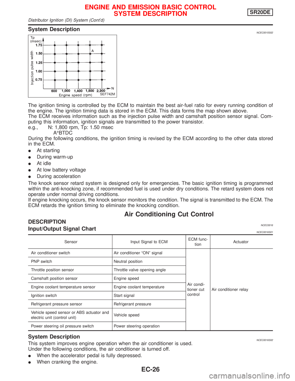
The ignition timing is controlled by the ECM to maintain the best air-fuel ratio for every running condition of
the engine. The ignition timing data is stored in the ECM. This data forms the map shown above.
The ECM receives information such as the injection pulse width and camshaft position sensor signal. Com-
puting this information, ignition signals are transmitted to the power transistor.
e.g., N: 1,800 rpm, Tp: 1.50 msec
AÉBTDC
During the following conditions, the ignition timing is revised by the ECM according to the other data stored
in the ECM.
IAt starting
IDuring warm-up
IAt idle
IAt low battery voltage
IDuring acceleration
The knock sensor retard system is designed only for emergencies. The basic ignition timing is programmed
within the anti-knocking zone, if recommended fuel is used under dry conditions. The retard system does not
operate under normal driving conditions.
If engine knocking occurs, the knock sensor monitors the condition. The signal is transmitted to the ECM. The
ECM retards the ignition timing to eliminate the knocking condition.
Air Conditioning Cut Control
DESCRIPTIONNCEC0016Input/Output Signal ChartNCEC0016S01
Sensor Input Signal to ECMECM func-
tionActuator
Air conditioner switch Air conditioner ªONº signal
Air condi-
tioner cut
controlAir conditioner relay PNP switch Neutral position
Throttle position sensor Throttle valve opening angle
Camshaft position sensor Engine speed
Engine coolant temperature sensor Engine coolant temperature
Ignition switch Start signal
Refrigerant pressure sensor Refrigerant pressure
Vehicle speed sensor or ABS actuator and
electric unit (control unit)Vehicle speed
Power steering oil pressure switch Power steering operation
System DescriptionNCEC0016S02This system improves engine operation when the air conditioner is used.
Under the following conditions, the air conditioner is turned off.
IWhen the accelerator pedal is fully depressed.
IWhen cranking the engine.
SEF742M
ENGINE AND EMISSION BASIC CONTROL
SYSTEM DESCRIPTIONSR20DE
Distributor Ignition (DI) System (Cont'd)
EC-26