1999 NISSAN PRIMERA differential
[x] Cancel search: differentialPage 1728 of 2267
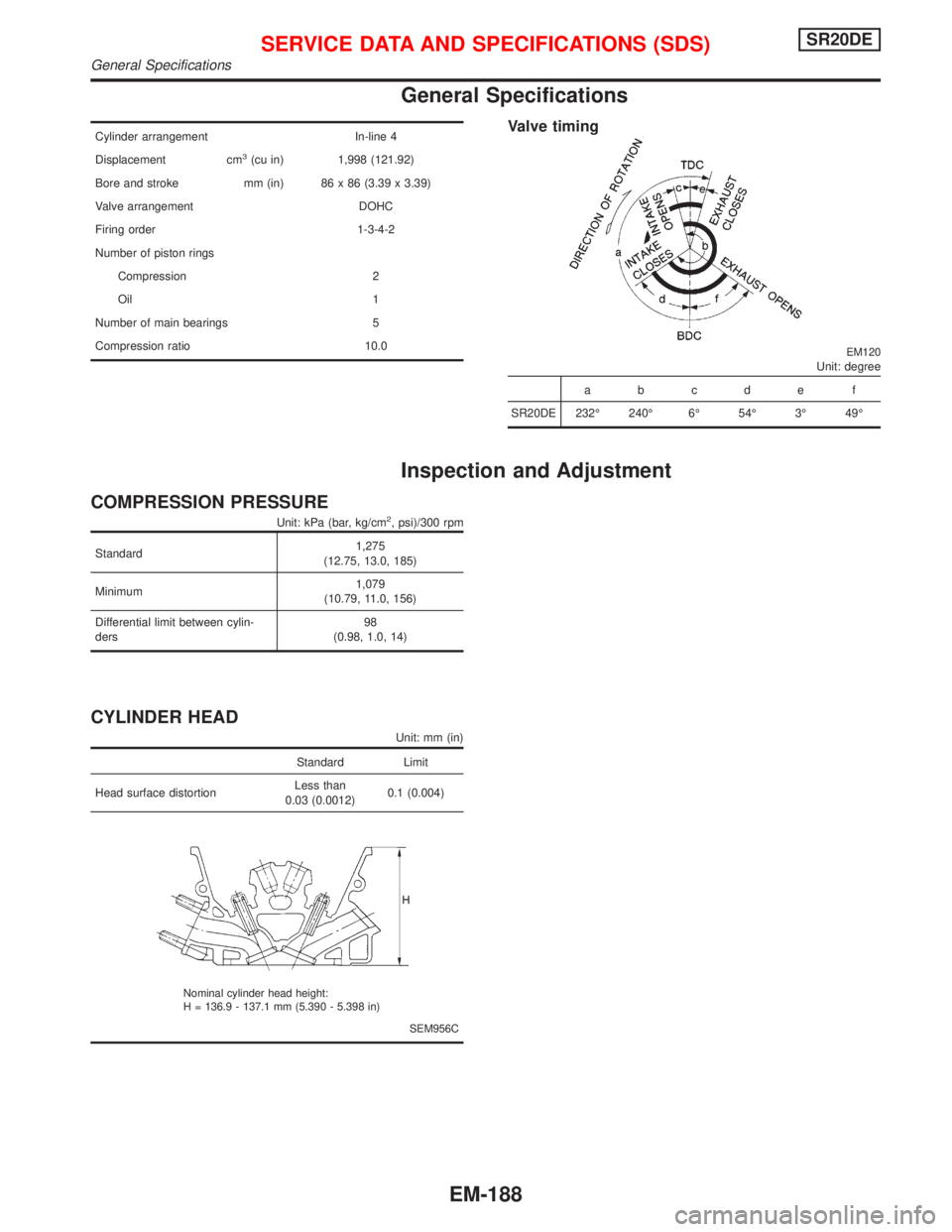
General Specifications
Cylinder arrangement In-line 4
Displacement cm
3(cu in) 1,998 (121.92)
Bore and stroke mm (in) 86 x 86 (3.39 x 3.39)
Valve arrangement DOHC
Firing order 1-3-4-2
Number of piston rings
Compression 2
Oil 1
Number of main bearings 5
Compression ratio 10.0
Valve timing
EM120Unit: degree
abcde f
SR20DE 232É 240É 6É 54É 3É 49É
Inspection and Adjustment
COMPRESSION PRESSURE
Unit: kPa (bar, kg/cm2, psi)/300 rpm
Standard1,275
(12.75, 13.0, 185)
Minimum1,079
(10.79, 11.0, 156)
Differential limit between cylin-
ders98
(0.98, 1.0, 14)
CYLINDER HEAD
Unit: mm (in)
Standard Limit
Head surface distortionLess than
0.03 (0.0012)0.1 (0.004)
SEM956C Nominal cylinder head height:
H = 136.9 - 137.1 mm (5.390 - 5.398 in)
SERVICE DATA AND SPECIFICATIONS (SDS)SR20DE
General Specifications
EM-188
Page 1744 of 2267
Precautions
lWhen installing each rubber part, final tightening must
be carried out under unladen condition* with tires on
ground.
*: Fuel, radiator coolant and engine oil full. Spare tire,
jack, hand tools and mats in designated positions.
lWhen removing each suspension part, check wheel
alignment and adjust if necessary.
lUse Tool when removing or installing brake tubes.
lAlways torque brake lines when installing.
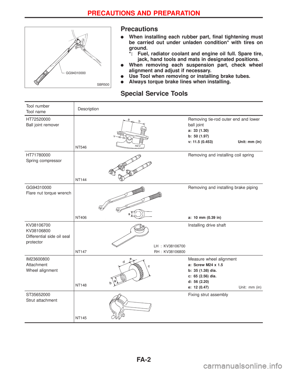
Special Service Tools
Tool number
Tool nameDescription
HT72520000
Ball joint remover
NT546
Removing tie-rod outer end and lower
ball joint
a: 33 (1.30)
b: 50 (1.97)
v: 11.5 (0.453) Unit: mm (in)
HT71780000
Spring compressor
NT144
Removing and installing coil spring
GG94310000
Flare nut torque wrench
NT406
Removing and installing brake piping
a: 10 mm (0.39 in)
KV38106700
KV38106800
Differential side oil seal
protector
LH : KV38106700
RH : KV38106800 NT147
Installing drive shaft
IM23600800
Attachment
Wheel alignment
NT148
Measure wheel alignment
a: Screw M24 x 1.5
b: 35 (1.38) dia.
c: 65 (2.56) dia.
d: 56 (2.20)
e: 12 (0.47)Unit: mm (in)
ST35652000
Strut attachment
NT145
Fixing strut assembly
SBR500 GG94310000
PRECAUTIONS AND PREPARATION
FA-2
Page 1758 of 2267
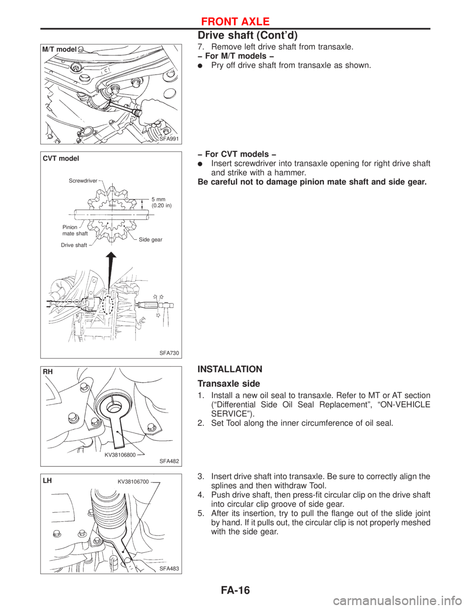
7. Remove left drive shaft from transaxle.
þ For M/T models þ
lPry off drive shaft from transaxle as shown.
þ For CVT models þ
lInsert screwdriver into transaxle opening for right drive shaft
and strike with a hammer.
Be careful not to damage pinion mate shaft and side gear.
INSTALLATION
Transaxle side
1. Install a new oil seal to transaxle. Refer to MT or AT section
(ªDifferential Side Oil Seal Replacementº, ªON-VEHICLE
SERVICEº).
2. Set Tool along the inner circumference of oil seal.
3. Insert drive shaft into transaxle. Be sure to correctly align the
splines and then withdraw Tool.
4. Push drive shaft, then press-fit circular clip on the drive shaft
into circular clip groove of side gear.
5. After its insertion, try to pull the flange out of the slide joint
by hand. If it pulls out, the circular clip is not properly meshed
with the side gear.
.
.M/T model
SFA991
SFA730 Screwdriver
Pinion
mate shaft
Drive shaft5mm
(0.20 in)
Side gear
CVT model
SFA482
RH
KV38106800
SFA483
LHKV38106700
FRONT AXLE
Drive shaft (Cont'd)
FA-16
Page 1847 of 2267
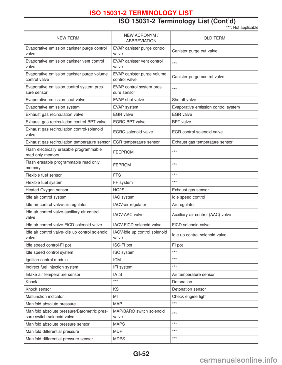
***: Not applicable
NEW TERMNEW ACRONYM /
ABBREVIATIONOLD TERM
Evaporative emission canister purge control
valveEVAP canister purge control
valveCanister purge cut valve
Evaporative emission canister vent control
valveEVAP canister vent control
valve***
Evaporative emission canister purge volume
control valveEVAP canister purge volume
control valveCanister purge control valve
Evaporative emission control system pres-
sure sensorEVAP control system pres-
sure sensor***
Evaporative emission shut valve EVAP shut valve Shutoff valve
Evaporative emission system EVAP system Evaporative emission control system
Exhaust gas recirculation valve EGR valve EGR valve
Exhaust gas recirculation control-BPT valve EGRC-BPT valve BPT valve
Exhaust gas recirculation control-solenoid
valveEGRC-solenoid valve EGR control solenoid valve
Exhaust gas recirculation temperature sensor EGR temperature sensor Exhaust gas temperature sensor
Flash electrically erasable programmable
read only memoryFEEPROM ***
Flash erasable programmable read only
memoryFEPROM ***
Flexible fuel sensor FFS ***
Flexible fuel system FF system ***
Heated Oxygen sensor HO2S Exhaust gas sensor
Idle air control system IAC system Idle speed control
Idle air control valve-air regulator IACV-air regulator Air regulator
Idle air control valve-auxiliary air control
valveIACV-AAC valve Auxiliary air control (AAC) valve
Idle air control valve-FICD solenoid valve IACV-FICD solenoid valve FICD solenoid valve
Idle air control valve-idle up control solenoid
valveIACV-idle up control solenoid
valveIdle up control solenoid valve
Idle speed control-FI pot ISC-FI pot FI pot
Idle speed control system ISC system ***
Ignition control module ICM ***
Indirect fuel injection system IFI system ***
Intake air temperature sensor IATS Air temperature sensor
Knock *** Detonation
Knock sensor KS Detonation sensor
Malfunction indicator MI Check engine light
Manifold absolute pressure MAP ***
Manifold absolute pressure/Barometric pres-
sure switch solenoid valveMAP/BARO switch solenoid
valve***
Manifold absolute pressure sensor MAPS ***
Manifold differential pressure MDP ***
Manifold differential pressure sensor MDPS ***
ISO 15031-2 TERMINOLOGY LIST
ISO 15031-2 Terminology List (Cont'd)
GI-52
Page 2021 of 2267
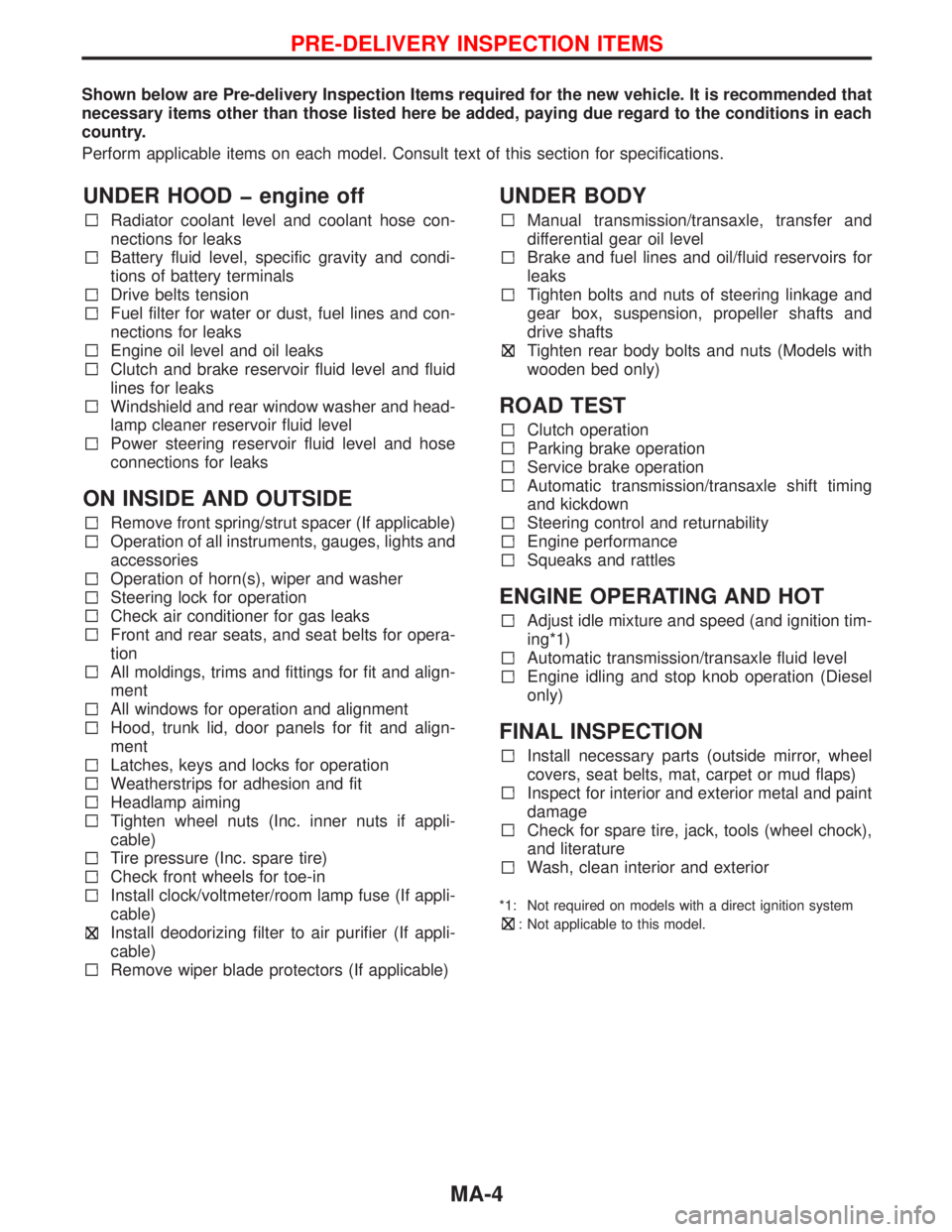
Shown below are Pre-delivery Inspection Items required for the new vehicle. It is recommended that
necessary items other than those listed here be added, paying due regard to the conditions in each
country.
Perform applicable items on each model. Consult text of this section for specifications.
UNDER HOOD engine off
Radiator coolant level and coolant hose con-
nections for leaks
Battery fluid level, specific gravity and condi-
tions of battery terminals
Drive belts tension
Fuel filter for water or dust, fuel lines and con-
nections for leaks
Engine oil level and oil leaks
Clutch and brake reservoir fluid level and fluid
lines for leaks
Windshield and rear window washer and head-
lamp cleaner reservoir fluid level
Power steering reservoir fluid level and hose
connections for leaks
ON INSIDE AND OUTSIDE
Remove front spring/strut spacer (If applicable)
Operation of all instruments, gauges, lights and
accessories
Operation of horn(s), wiper and washer
Steering lock for operation
Check air conditioner for gas leaks
Front and rear seats, and seat belts for opera-
tion
All moldings, trims and fittings for fit and align-
ment
All windows for operation and alignment
Hood, trunk lid, door panels for fit and align-
ment
Latches, keys and locks for operation
Weatherstrips for adhesion and fit
Headlamp aiming
Tighten wheel nuts (Inc. inner nuts if appli-
cable)
Tire pressure (Inc. spare tire)
Check front wheels for toe-in
Install clock/voltmeter/room lamp fuse (If appli-
cable)
Install deodorizing filter to air purifier (If appli-
cable)
Remove wiper blade protectors (If applicable)
UNDER BODY
Manual transmission/transaxle, transfer and
differential gear oil level
Brake and fuel lines and oil/fluid reservoirs for
leaks
Tighten bolts and nuts of steering linkage and
gear box, suspension, propeller shafts and
drive shafts
Tighten rear body bolts and nuts (Models with
wooden bed only)
ROAD TEST
Clutch operation
Parking brake operation
Service brake operation
Automatic transmission/transaxle shift timing
and kickdown
Steering control and returnability
Engine performance
Squeaks and rattles
ENGINE OPERATING AND HOT
Adjust idle mixture and speed (and ignition tim-
ing*1)
Automatic transmission/transaxle fluid level
Engine idling and stop knob operation (Diesel
only)
FINAL INSPECTION
Install necessary parts (outside mirror, wheel
covers, seat belts, mat, carpet or mud flaps)
Inspect for interior and exterior metal and paint
damage
Check for spare tire, jack, tools (wheel chock),
and literature
Wash, clean interior and exterior
*1: Not required on models with a direct ignition system
: Not applicable to this model.
PRE-DELIVERY INSPECTION ITEMS
MA-4
Page 2078 of 2267
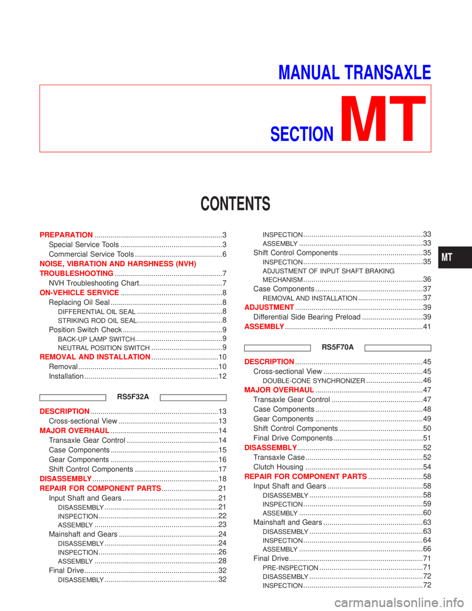
MANUAL TRANSAXLE
SECTION
MT
CONTENTS
PREPARATION...............................................................3
Special Service Tools ..................................................3
Commercial Service Tools ...........................................6
NOISE, VIBRATION AND HARSHNESS (NVH)
TROUBLESHOOTING.....................................................7
NVH Troubleshooting Chart.........................................7
ON-VEHICLE SERVICE..................................................8
Replacing Oil Seal .......................................................8
DIFFERENTIAL OIL SEAL..........................................8
STRIKING ROD OIL SEAL..........................................8
Position Switch Check .................................................9
BACK-UP LAMP SWITCH...........................................9
NEUTRAL POSITION SWITCH...................................9
REMOVAL AND INSTALLATION.................................10
Removal .....................................................................10
Installation ..................................................................12
RS5F32A
DESCRIPTION...............................................................13
Cross-sectional View .................................................13
MAJOR OVERHAUL.....................................................14
Transaxle Gear Control .............................................14
Case Components .....................................................15
Gear Components .....................................................16
Shift Control Components .........................................17
DISASSEMBLY..............................................................18
REPAIR FOR COMPONENT PARTS............................21
Input Shaft and Gears ...............................................21
DISASSEMBLY........................................................21
INSPECTION...........................................................22
ASSEMBLY.............................................................23
Mainshaft and Gears .................................................24
DISASSEMBLY........................................................24
INSPECTION...........................................................26
ASSEMBLY.............................................................28
Final Drive..................................................................32
DISASSEMBLY........................................................32
INSPECTION...........................................................33
ASSEMBLY.............................................................33
Shift Control Components .........................................35
INSPECTION...........................................................35
ADJUSTMENT OF INPUT SHAFT BRAKING
MECHANISM
...........................................................36
Case Components .....................................................37
REMOVAL AND INSTALLATION................................37
ADJUSTMENT...............................................................39
Differential Side Bearing Preload ..............................39
ASSEMBLY....................................................................41
RS5F70A
DESCRIPTION...............................................................45
Cross-sectional View .................................................45
DOUBLE-CONE SYNCHRONIZER............................46
MAJOR OVERHAUL.....................................................47
Transaxle Gear Control .............................................47
Case Components .....................................................48
Gear Components .....................................................49
Shift Control Components .........................................50
Final Drive Components ............................................51
DISASSEMBLY..............................................................52
Transaxle Case ..........................................................52
Clutch Housing ..........................................................54
REPAIR FOR COMPONENT PARTS...........................58
Input Shaft and Gears ...............................................58
DISASSEMBLY........................................................58
INSPECTION...........................................................59
ASSEMBLY.............................................................60
Mainshaft and Gears .................................................63
DISASSEMBLY........................................................63
INSPECTION...........................................................64
ASSEMBLY.............................................................66
Final Drive..................................................................71
PRE-INSPECTION...................................................71
DISASSEMBLY........................................................72
INSPECTION...........................................................72
MT
Page 2079 of 2267
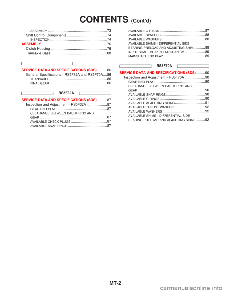
ASSEMBLY.............................................................73
Shift Control Components .........................................74
INSPECTION...........................................................74
ASSEMBLY....................................................................76
Clutch Housing ..........................................................76
Transaxle Case ..........................................................80
SERVICE DATA AND SPECIFICATIONS (SDS)..........86
General Specifications - RS5F32A and RS5F70A ....86
TRANSAXLE...........................................................86
FINAL GEAR...........................................................86
RS5F32A
SERVICE DATA AND SPECIFICATIONS (SDS)..........87
Inspection and Adjustment - RS5F32A .....................87
GEAR END PLAY....................................................87
CLEARANCE BETWEEN BAULK RING AND
GEAR
.....................................................................87
AVAILABLE CHECK PLUGS.....................................87
AVAILABLE SNAP RINGS........................................87
AVAILABLE C-RINGS...............................................87
AVAILABLE SPACERS.............................................88
AVAILABLE WASHERS............................................88
AVAILABLE SHIMS - DIFFERENTIAL SIDE
BEARING PRELOAD AND ADJUSTING SHIM
............88
INPUT SHAFT BRAKING MECHANISM.....................89
MAINSHAFT END PLAY...........................................89
RS5F70A
SERVICE DATA AND SPECIFICATIONS (SDS).........90
Inspection and Adjustment - RS5F70A .....................90
GEAR END PLAY....................................................90
CLEARANCE BETWEEN BAULK RING AND
GEAR
.....................................................................90
AVAILABLE SNAP RINGS........................................90
AVAILABLE C-RINGS..............................................90
AVAILABLE ADJUSTING SHIMS...............................91
AVAILABLE THRUST WASHER................................92
AVAILABLE WASHERS............................................92
AVAILABLE SHIMS - DIFFERENTIAL SIDE
BEARING PRELOAD AND ADJUSTING SHIM
...........92
CONTENTS(Cont'd)
MT-2
Page 2080 of 2267
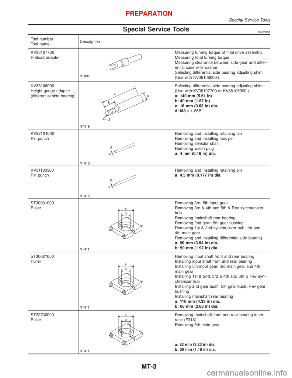
Special Service ToolsNCMT0001
Tool number
Tool nameDescription
KV38107700
Preload adapter
NT087
Measuring turning torque of final drive assembly
Measuring total turning torque
Measuring clearance between side gear and differ-
ential case with washer
Selecting differential side bearing adjusting shim
(Use with KV38106000.)
KV38106000
Height gauge adapter
(differential side bearing)
NT418
Selecting differential side bearing adjusting shim
(Use with KV38107700 or KV38105900.)
a: 140 mm (5.51 in)
b: 40 mm (1.57 in)
c: 16 mm (0.63 in) dia.
d: M8´1.25P
KV32101000
Pin punch
NT410
Removing and installing retaining pin
Removing and installing lock pin
Removing selector shaft
Removing welch plug
a: 4 mm (0.16 in) dia.
KV31100300
Pin punch
NT410
Removing and installing retaining pin
a: 4.5 mm (0.177 in) dia.
ST30031000
Puller
NT411
Removing 3rd, 5th input gear
Removing 3rd & 4th and 5th & Rev synchronizer
hub
Removing mainshaft rear bearing
Removing 2nd gear, 5th gear bushing
Removing 1st & 2nd synchronizer hub, 1st and
4th main gear
Removing and installing differential side bearing
a: 90 mm (3.54 in) dia.
b: 50 mm (1.97 in) dia.
ST30021000
Puller
NT411
Removing input shaft front and rear bearing
Installing input shaft front and rear bearing
Installing 5th input gear, 3rd main gear and 4th
main gear
Installing 1st & 2nd, 3rd & 4th and 5th & Rev syn-
chronizer hub
Installing 2nd gear bush, 5th gear bush, Rev gear
bushing
Installing mainshaft rear bearing
a: 110 mm (4.33 in) dia.
b: 68 mm (2.68 in) dia.
ST22730000
Puller
NT411
Removing mainshaft front and rear bearing inner
race (F31A)
Removing 5th main gear
a: 82 mm (3.23 in) dia.
b: 30 mm (1.18 in) dia.
PREPARATION
Special Service Tools
MT-3