Page 2149 of 2267
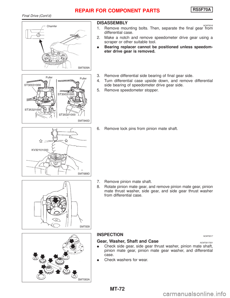
DISASSEMBLYNCMT00161. Remove mounting bolts. Then, separate the final gear from
differential case.
2. Make a notch and remove speedometer drive gear using a
scraper or other suitable tool.
IBearing replacer cannot be positioned unless speedom-
eter drive gear is removed.
3. Remove differential side bearing of final gear side.
4. Turn differential case upside down, and remove differential
side bearing of speedometer drive gear side.
5. Remove speedometer stopper.
6. Remove lock pins from pinion mate shaft.
7. Remove pinion mate shaft.
8. Rotate pinion mate gear, and remove pinion mate gear, pinion
mate thrust washer, side gear, and side gear thrust washer
from differential case.
INSPECTIONNCMT0017
Gear, Washer, Shaft and CaseNCMT0017S01
ICheck side gear, side gear thrust washer, pinion mate shaft,
pinion mate gear, pinion mate gear washer, and differential
case.
ICheck washers for wear.
SMT609A Chamfer
SMT840D Puller
Puller
SMT689D
SMT839
SMT083A
REPAIR FOR COMPONENT PARTSRS5F70A
Final Drive (Cont'd)
MT-72
Page 2150 of 2267
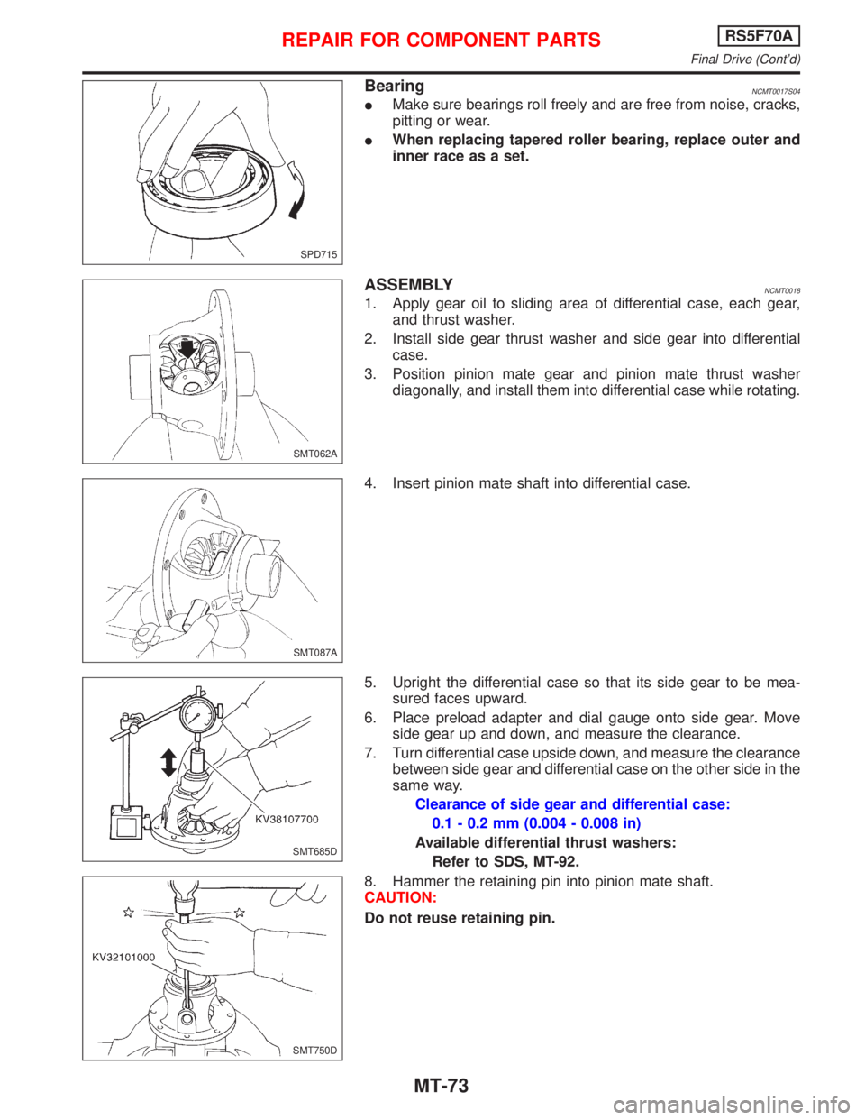
BearingNCMT0017S04
IMake sure bearings roll freely and are free from noise, cracks,
pitting or wear.
IWhen replacing tapered roller bearing, replace outer and
inner race as a set.
ASSEMBLYNCMT0018
1. Apply gear oil to sliding area of differential case, each gear,
and thrust washer.
2. Install side gear thrust washer and side gear into differential
case.
3. Position pinion mate gear and pinion mate thrust washer
diagonally, and install them into differential case while rotating.
4. Insert pinion mate shaft into differential case.
5. Upright the differential case so that its side gear to be mea-
sured faces upward.
6. Place preload adapter and dial gauge onto side gear. Move
side gear up and down, and measure the clearance.
7. Turn differential case upside down, and measure the clearance
between side gear and differential case on the other side in the
same way.
Clearance of side gear and differential case:
0.1 - 0.2 mm (0.004 - 0.008 in)
Available differential thrust washers:
Refer to SDS, MT-92.
8. Hammer the retaining pin into pinion mate shaft.
CAUTION:
Do not reuse retaining pin.
SPD715
SMT062A
SMT087A
SMT685D
SMT750D
REPAIR FOR COMPONENT PARTSRS5F70A
Final Drive (Cont'd)
MT-73
Page 2151 of 2267
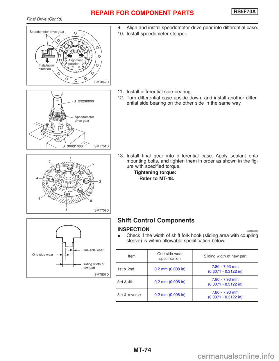
9. Align and install speedometer drive gear into differential case.
10. Install speedometer stopper.
11. Install differential side bearing.
12. Turn differential case upside down, and install another differ-
ential side bearing on the other side in the same way.
13. Install final gear into differential case. Apply sealant onto
mounting bolts, and tighten them in order as shown in the fig-
ure with specified torque.
Tightening torque:
Refer to MT-48.
Shift Control Components
INSPECTIONNCMT0019
ICheck if the width of shift fork hook (sliding area with coupling
sleeve) is within allowable specification below.
ItemOne-side wear
specificationSliding width of new part
1st & 2nd0.2 mm (0.008 in)7.80 - 7.93 mm
(0.3071 - 0.3122 in)
3rd & 4th0.2 mm (0.008 in)7.80 - 7.93 mm
(0.3071 - 0.3122 in)
5th & reverse0.2 mm (0.008 in)7.80 - 7.93 mm
(0.3071 - 0.3122 in)
SMT842D Speedometer drive gear
Installation
directionAlignment
position
SMT751D Speedometer
drive gear
SMT752D
SMT801D One-side wear
Sliding width of
new part One-side wear
REPAIR FOR COMPONENT PARTSRS5F70A
Final Drive (Cont'd)
MT-74
Page 2153 of 2267
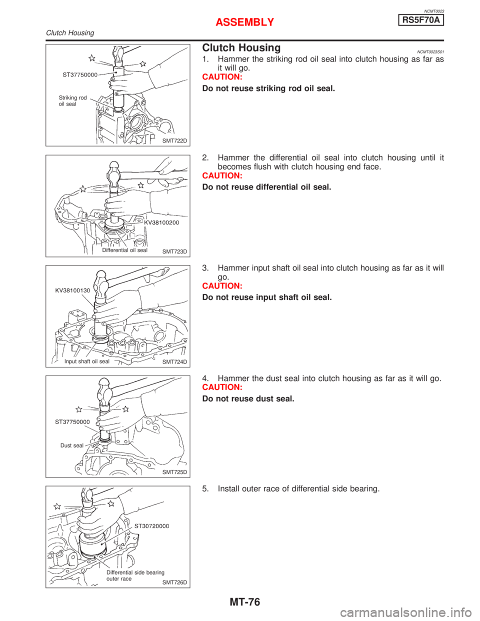
NCMT0023
Clutch HousingNCMT0023S01
1. Hammer the striking rod oil seal into clutch housing as far as
it will go.
CAUTION:
Do not reuse striking rod oil seal.
2. Hammer the differential oil seal into clutch housing until it
becomes flush with clutch housing end face.
CAUTION:
Do not reuse differential oil seal.
3. Hammer input shaft oil seal into clutch housing as far as it will
go.
CAUTION:
Do not reuse input shaft oil seal.
4. Hammer the dust seal into clutch housing as far as it will go.
CAUTION:
Do not reuse dust seal.
5. Install outer race of differential side bearing.
SMT722D Striking rod
oil seal
SMT723D Differential oil seal
SMT724D Input shaft oil seal
SMT725D Dust seal
SMT726D Differential side bearing
outer race
ASSEMBLYRS5F70A
Clutch Housing
MT-76
Page 2156 of 2267
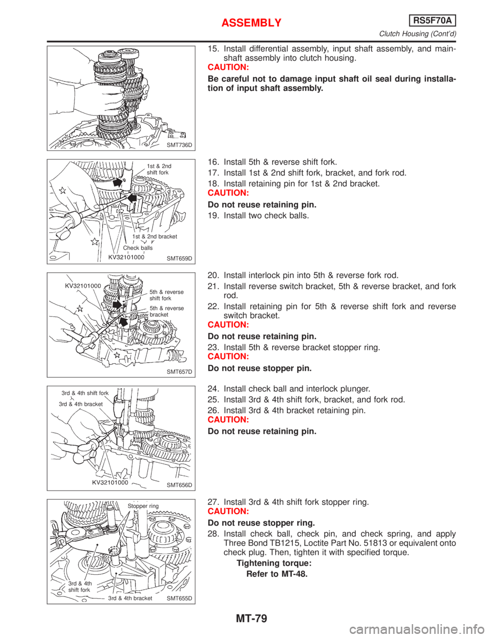
15. Install differential assembly, input shaft assembly, and main-
shaft assembly into clutch housing.
CAUTION:
Be careful not to damage input shaft oil seal during installa-
tion of input shaft assembly.
16. Install 5th & reverse shift fork.
17. Install 1st & 2nd shift fork, bracket, and fork rod.
18. Install retaining pin for 1st & 2nd bracket.
CAUTION:
Do not reuse retaining pin.
19. Install two check balls.
20. Install interlock pin into 5th & reverse fork rod.
21. Install reverse switch bracket, 5th & reverse bracket, and fork
rod.
22. Install retaining pin for 5th & reverse shift fork and reverse
switch bracket.
CAUTION:
Do not reuse retaining pin.
23. Install 5th & reverse bracket stopper ring.
CAUTION:
Do not reuse stopper pin.
24. Install check ball and interlock plunger.
25. Install 3rd & 4th shift fork, bracket, and fork rod.
26. Install 3rd & 4th bracket retaining pin.
CAUTION:
Do not reuse retaining pin.
27. Install 3rd & 4th shift fork stopper ring.
CAUTION:
Do not reuse stopper ring.
28. Install check ball, check pin, and check spring, and apply
Three Bond TB1215, Loctite Part No. 51813 or equivalent onto
check plug. Then, tighten it with specified torque.
Tightening torque:
Refer to MT-48.
SMT736D
SMT659D 1st & 2nd
shift fork
1st & 2nd bracket
Check balls
SMT657D 5th & reverse
shift fork
5th & reverse
bracket
SMT656D 3rd & 4th shift fork
3rd & 4th bracket
SMT655D Stopper ring
3rd & 4th
shift fork.3rd & 4th bracket
ASSEMBLYRS5F70A
Clutch Housing (Cont'd)
MT-79
Page 2157 of 2267
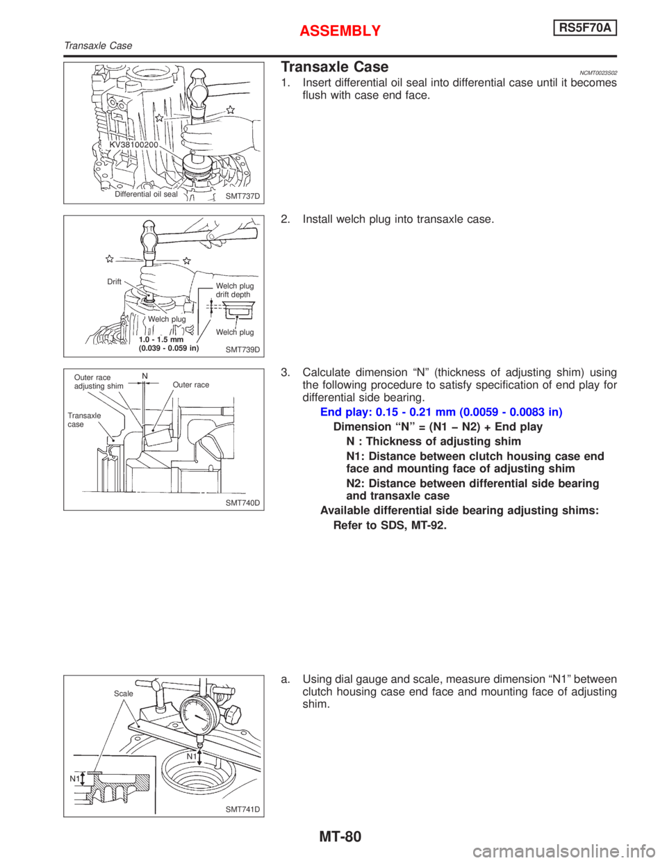
Transaxle CaseNCMT0023S02
1. Insert differential oil seal into differential case until it becomes
flush with case end face.
2. Install welch plug into transaxle case.
3. Calculate dimension ªNº (thickness of adjusting shim) using
the following procedure to satisfy specification of end play for
differential side bearing.
End play: 0.15 - 0.21 mm (0.0059 - 0.0083 in)
Dimension ªNº = (N1 þ N2) + End play
N : Thickness of adjusting shim
N1: Distance between clutch housing case end
face and mounting face of adjusting shim
N2: Distance between differential side bearing
and transaxle case
Available differential side bearing adjusting shims:
Refer to SDS, MT-92.
a. Using dial gauge and scale, measure dimension ªN1º between
clutch housing case end face and mounting face of adjusting
shim.
SMT737D Differential oil seal
SMT739D Welch plug
drift depth
Welch plug Welch plug
1.0 - 1.5 mm
(0.039 - 0.059 in) Drift
SMT740D Outer race
adjusting shim
Transaxle
caseOuter race
SMT741D Scale
ASSEMBLYRS5F70A
Transaxle Case
MT-80
Page 2158 of 2267
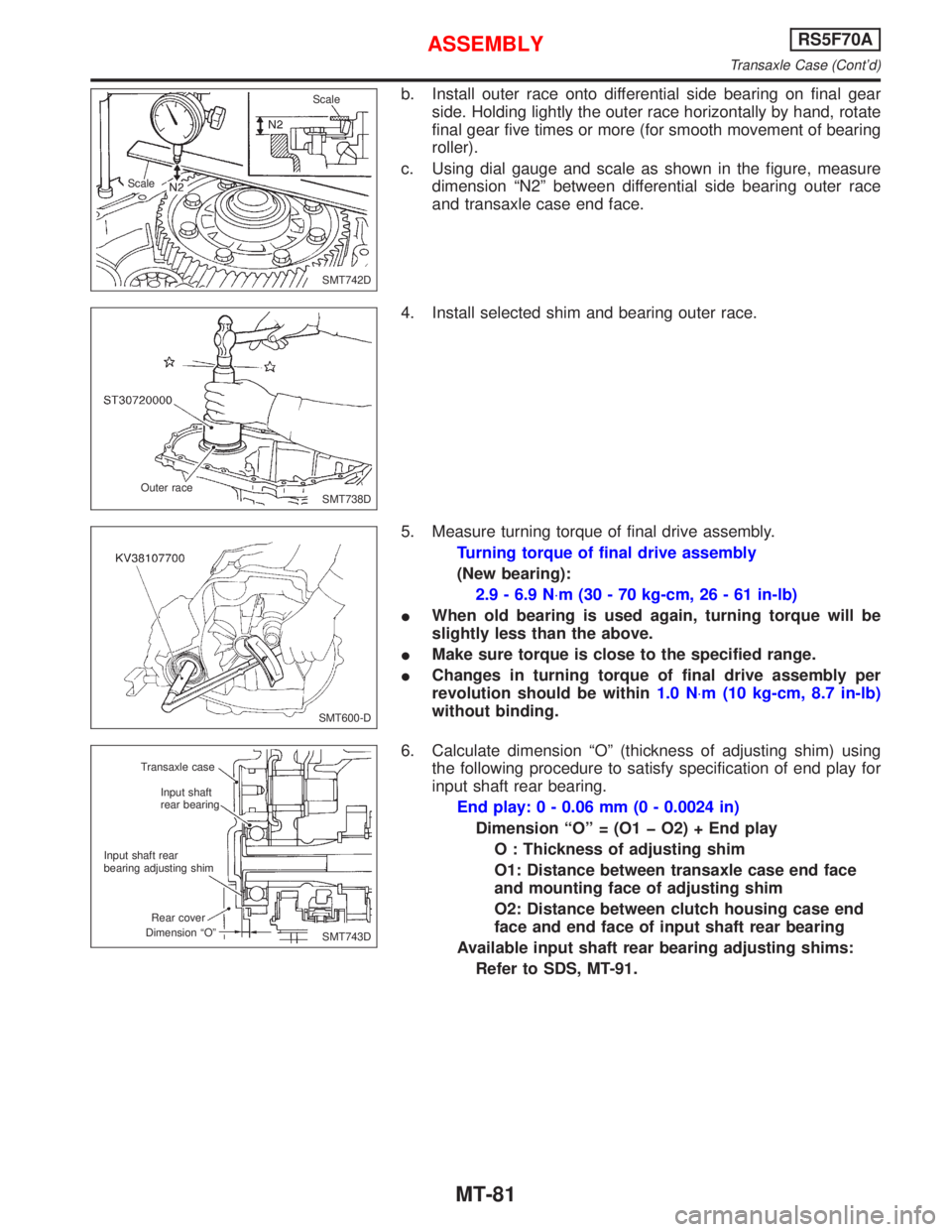
b. Install outer race onto differential side bearing on final gear
side. Holding lightly the outer race horizontally by hand, rotate
final gear five times or more (for smooth movement of bearing
roller).
c. Using dial gauge and scale as shown in the figure, measure
dimension ªN2º between differential side bearing outer race
and transaxle case end face.
4. Install selected shim and bearing outer race.
5. Measure turning torque of final drive assembly.
Turning torque of final drive assembly
(New bearing):
2.9 - 6.9 N×m (30 - 70 kg-cm, 26 - 61 in-lb)
IWhen old bearing is used again, turning torque will be
slightly less than the above.
IMake sure torque is close to the specified range.
IChanges in turning torque of final drive assembly per
revolution should be within1.0 N×m (10 kg-cm, 8.7 in-lb)
without binding.
6. Calculate dimension ªOº (thickness of adjusting shim) using
the following procedure to satisfy specification of end play for
input shaft rear bearing.
End play: 0 - 0.06 mm (0 - 0.0024 in)
Dimension ªOº = (O1 þ O2) + End play
O : Thickness of adjusting shim
O1: Distance between transaxle case end face
and mounting face of adjusting shim
O2: Distance between clutch housing case end
face and end face of input shaft rear bearing
Available input shaft rear bearing adjusting shims:
Refer to SDS, MT-91.
SMT742D ScaleScale
SMT738D Outer race
SMT600-D
SMT743D Transaxle case
Input shaft
rear bearing
Input shaft rear
bearing adjusting shim
Rear cover
Dimension ªOº
ASSEMBLYRS5F70A
Transaxle Case (Cont'd)
MT-81
Page 2165 of 2267
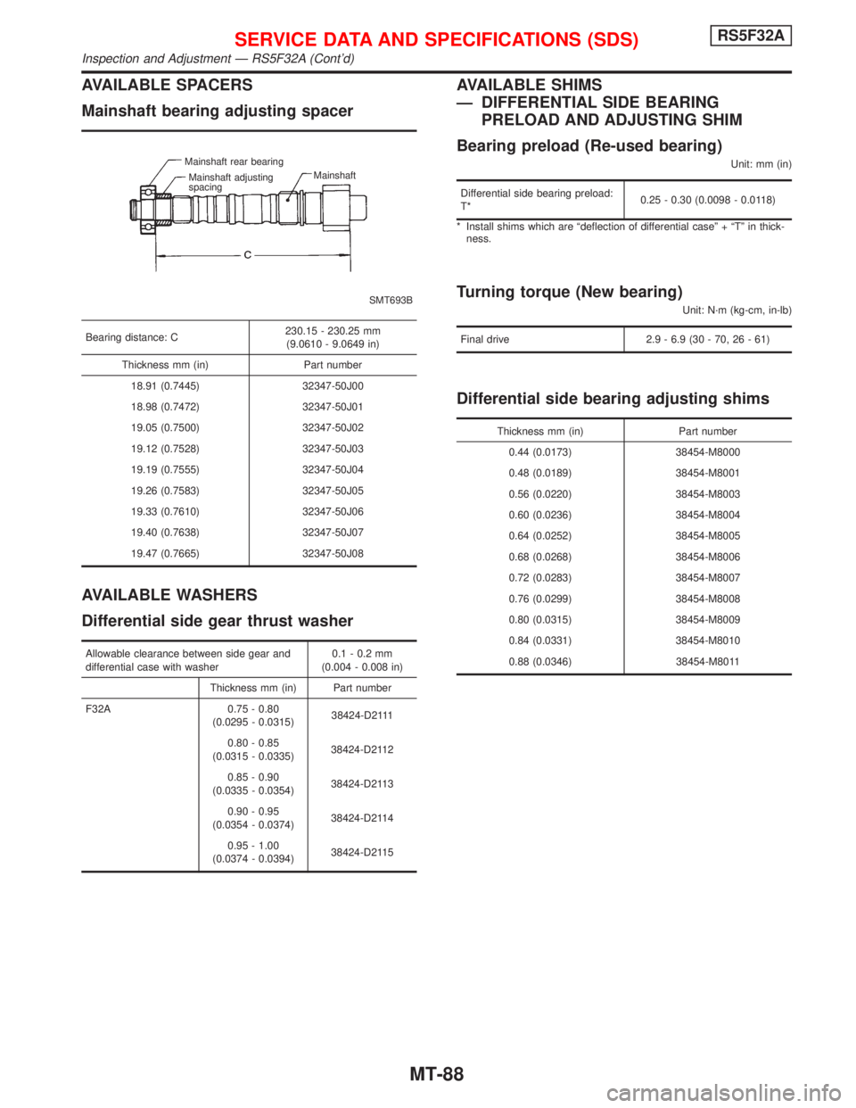
AVAILABLE SPACERS
Mainshaft bearing adjusting spacer
SMT693B Mainshaft rear bearing
Mainshaft adjusting
spacingMainshaft
Bearing distance: C230.15 - 230.25 mm
(9.0610 - 9.0649 in)
Thickness mm (in) Part number
18.91 (0.7445) 32347-50J00
18.98 (0.7472) 32347-50J01
19.05 (0.7500) 32347-50J02
19.12 (0.7528) 32347-50J03
19.19 (0.7555) 32347-50J04
19.26 (0.7583) 32347-50J05
19.33 (0.7610) 32347-50J06
19.40 (0.7638) 32347-50J07
19.47 (0.7665) 32347-50J08
AVAILABLE WASHERS
Differential side gear thrust washer
Allowable clearance between side gear and
differential case with washer0.1 - 0.2 mm
(0.004 - 0.008 in)
Thickness mm (in) Part number
F32A 0.75 - 0.80
(0.0295 - 0.0315)38424-D2111
0.80 - 0.85
(0.0315 - 0.0335)38424-D2112
0.85 - 0.90
(0.0335 - 0.0354)38424-D2113
0.90 - 0.95
(0.0354 - 0.0374)38424-D2114
0.95 - 1.00
(0.0374 - 0.0394)38424-D2115
AVAILABLE SHIMS
Ð DIFFERENTIAL SIDE BEARING
PRELOAD AND ADJUSTING SHIM
Bearing preload (Re-used bearing)
Unit: mm (in)
Differential side bearing preload:
T*0.25 - 0.30 (0.0098 - 0.0118)
* Install shims which are ªdeflection of differential caseº + ªTº in thick-
ness.
Turning torque (New bearing)
Unit: N´m (kg-cm, in-lb)
Final drive 2.9 - 6.9 (30 - 70, 26 - 61)
Differential side bearing adjusting shims
Thickness mm (in) Part number
0.44 (0.0173) 38454-M8000
0.48 (0.0189) 38454-M8001
0.56 (0.0220) 38454-M8003
0.60 (0.0236) 38454-M8004
0.64 (0.0252) 38454-M8005
0.68 (0.0268) 38454-M8006
0.72 (0.0283) 38454-M8007
0.76 (0.0299) 38454-M8008
0.80 (0.0315) 38454-M8009
0.84 (0.0331) 38454-M8010
0.88 (0.0346) 38454-M8011
SERVICE DATA AND SPECIFICATIONS (SDS)RS5F32A
Inspection and Adjustment Ð RS5F32A (Cont'd)
MT-88