Page 523 of 666

Introduction
The Automatic Temperature Control (ATC) system provides automatic regulation of the vehicles interior
temperature. The operator selects ªset temperatureº, on which the regulation is based, regardless of the
outside temperature changes. This is done by utilizing a microcomputer, also referred to as the automatic
amplifier, which receives input signals from several sensors. The automatic amplifier uses these input sig-
nals (including the set temperature) to automatically control the ATC system's outlet air volume, air tem-
perature and air distribution.
Features
Air mix door control
The air mix door is automatically controlled so that in-vehicle temperature will reach, and be maintained at
the operator selected ªset temperatureº. For a given set temperature, the air mix door position will depend
on: Ambient temperature, in-vehicle temperature, amount of sunload, and intake air temperature.
Fan speed control
Blower speed is automatically controlled based on temperature setting, ambient temperature, in-vehicle
temperature, intake air temperature, amount of sunload and air mix door position.
With FAN switch set to ªAUTOº, the blower motor starts to gradually increase air flow volume.
When engine coolant temperature is low, the blower motor operation is delayed to prevent cool air from
flowing.
Intake door control
The intake door position will be determined by: Ambient temperature, in-vehicle temperature, and whether
the compressor is on or off.
Outlet door control
The outlet door position will be determined by: Ambient temperature, in-vehicle temperature, intake air
temperature, and amount of sunload.
Magnet clutch control
The compressor operation (ON-OFF) is automatically controlled by the ambient sensor to prevent compres-
sor damage in very cold ambient temperatures.
Self-diagnostic system
The self-diagnostic system consists of five steps. Each step can be accessed by pushing the switches on
the automatic amplifier.
Memory function
With ignition switch turned OFF, the auto amplifier stores in memory the set temperature and inputs of vari-
ous switches. When the ignition switch is turned ON, the system begins operation with the information stored
in memory. The system, then immediately compensates for the actual operating conditions.
DESCRIPTIONAUTO
HA-2023
Page 524 of 666
Overview of Control System
The control system consists of input sensors, switches, the auto-
matic amplifier (microcomputer) and outputs. The relationship of
these components is shown in the diagram below:
Control Operation
RHA467H
RHA468H
DESCRIPTIONAUTO
HA-2024
Page 533 of 666

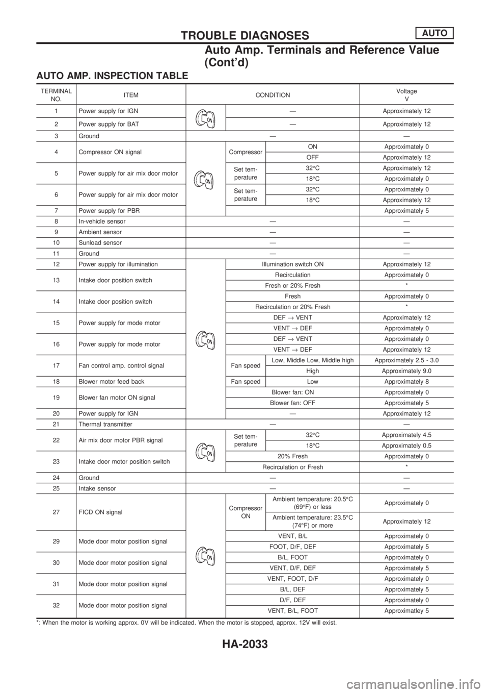
AUTO AMP. INSPECTION TABLE
TERMINAL
NO.ITEM CONDITIONVoltage
V
1 Power supply for IGN
Ð Approximately 12
2 Power supply for BAT Ð Approximately 12
3 Ground Ð Ð
4 Compressor ON signal
CompressorON Approximately 0
OFF Approximately 12
5 Power supply for air mix door motorSet tem-
perature32ÉC Approximately 12
18ÉC Approximately 0
6 Power supply for air mix door motorSet tem-
perature32ÉC Approximately 0
18ÉC Approximately 12
7 Power supply for PBRApproximately 5
8 In-vehicle sensor Ð Ð
9 Ambient sensor Ð Ð
10 Sunload sensor Ð Ð
11 Ground Ð Ð
12 Power supply for illumination
Illumination switch ON Approximately 12
13 Intake door position switchRecirculation Approximately 0
Fresh or 20% Fresh *
14 Intake door position switchFresh Approximately 0
Recirculation or 20% Fresh *
15 Power supply for mode motorDEF®VENT Approximately 12
VENT®DEF Approximately 0
16 Power supply for mode motorDEF®VENT Approximately 0
VENT®DEF Approximately 12
17 Fan control amp. control signal Fan speedLow, Middle Low, Middle high Approximately 2.5 - 3.0
High Approximately 9.0
18 Blower motor feed back Fan speed Low Approximately 8
19 Blower fan motor ON signalBlower fan: ON Approximately 0
Blower fan: OFF Approximately 5
20 Power supply for IGN Ð Approximately 12
21 Thermal transmitter Ð Ð
22 Air mix door motor PBR signal
Set tem-
perature32ÉC Approximately 4.5
18ÉC Approximately 0.5
23 Intake door motor position switch20% Fresh Approximately 0
Recirculation or Fresh *
24 Ground Ð Ð
25 Intake sensor Ð Ð
27 FICD ON signal
Compressor
ONAmbient temperature: 20.5ÉC
(69ÉF) or lessApproximately 0
Ambient temperature: 23.5ÉC
(74ÉF) or moreApproximately 12
29 Mode door motor position signalVENT, B/L Approximately 0
FOOT, D/F, DEF Approximately 5
30 Mode door motor position signalB/L, FOOT Approximately 0
VENT, D/F, DEF Approximately 5
31 Mode door motor position signalVENT, FOOT, D/F Approximately 0
B/L, DEF Approximately 5
32 Mode door motor position signalD/F, DEF Approximately 0
VENT, B/L, FOOT Approximatley 5
*: When the motor is working approx. 0V will be indicated. When the motor is stopped, approx. 12V will exist.
TROUBLE DIAGNOSESAUTO
Auto Amp. Terminals and Reference Value
(Cont'd)
HA-2033
Page 534 of 666

Self-diagnosis
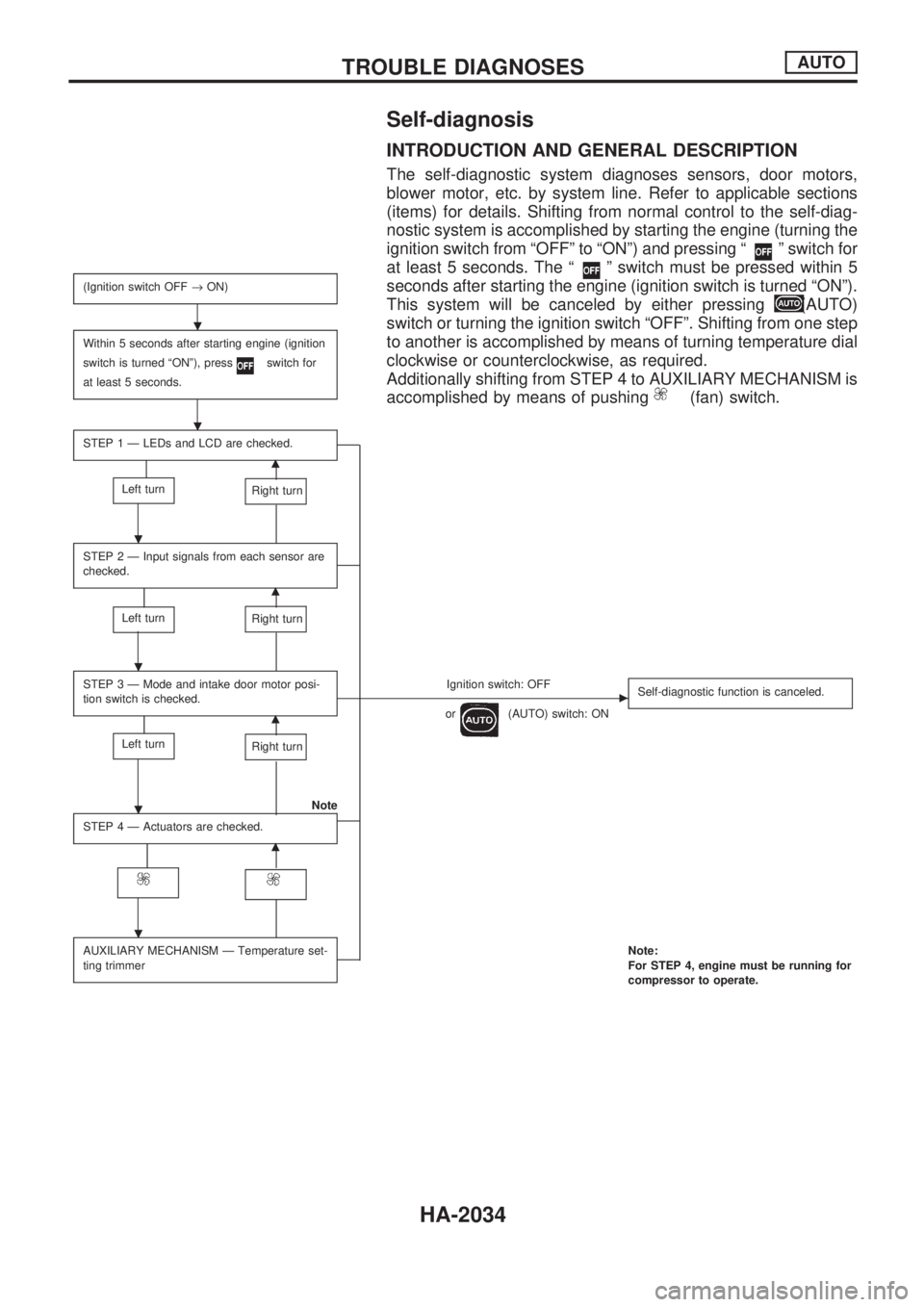
INTRODUCTION AND GENERAL DESCRIPTION
The self-diagnostic system diagnoses sensors, door motors,
blower motor, etc. by system line. Refer to applicable sections
(items) for details. Shifting from normal control to the self-diag-
nostic system is accomplished by starting the engine (turning the
ignition switch from ªOFFº to ªONº) and pressing ª
º switch for
at least 5 seconds. The ª
º switch must be pressed within 5
seconds after starting the engine (ignition switch is turned ªONº).
This system will be canceled by either pressing
(AUTO)
switch or turning the ignition switch ªOFFº. Shifting from one step
to another is accomplished by means of turning temperature dial
clockwise or counterclockwise, as required.
Additionally shifting from STEP 4 to AUXILIARY MECHANISM is
accomplished by means of pushing
(fan) switch.
(Ignition switch OFF®ON)
Within 5 seconds after starting engine (ignition
switch is turned ªONº), press
switch for
at least 5 seconds.
STEP 1 Ð LEDs and LCD are checked.
m
Left turnRight turn
STEP 2 Ð Input signals from each sensor are
checked.
m
Left turnRight turn
STEP 3 Ð Mode and intake door motor posi-
tion switch is checked.Ignition switch: OFFc
or(AUTO) switch: ONSelf-diagnostic function is canceled.m
Left turnRight turn
Note
STEP 4 Ð Actuators are checked.
m
AUXILIARY MECHANISM Ð Temperature set-
ting trimmerNote:
For STEP 4, engine must be running for
compressor to operate.
.
.
.
.
.
.
TROUBLE DIAGNOSESAUTO
HA-2034
Page 536 of 666
VA
STEP 2 - SENSOR CIRCUITS ARE
CHECKED FOR OPEN OR SHORT
CIRCUIT.
Does code No.
appear on the dis-
play?
YesNo
.
Turn temperature
dial clockwise.Refer to the following chart for malfunctioning code
No.
(If two or more sensors malfunction, corresponding
code Nos. blink respectively two times.)
*1: Conduct self-diagnosis STEP 2 under sunshine.
When conducting indoors, aim a light (more than
60W) at sunload sensor, otherwise Code No.
will indicate despite that sunload sensor is func-
tioning properly.
VB
(Go to next page.)
Code No.Malfunctioning sensor
(including circuits)Reference
page
Ambient sensor HA-2080A/C LED
In-vehicle sensor HA-2082A/C LED
Sunload sensor*1 HA-2084A/C LED
Air mix door motor PBR HA-2055A/C LED
RHA970DA
RHA528G
RHA501A
.
.
.
TROUBLE DIAGNOSESAUTO
Self-diagnosis (Cont'd)
HA-2036
Page 545 of 666

A/C System
TROUBLE DIAGNOSIS PROCEDURE FOR A/C SYSTEM
SYMPTOM:
lA/C system does not come on.
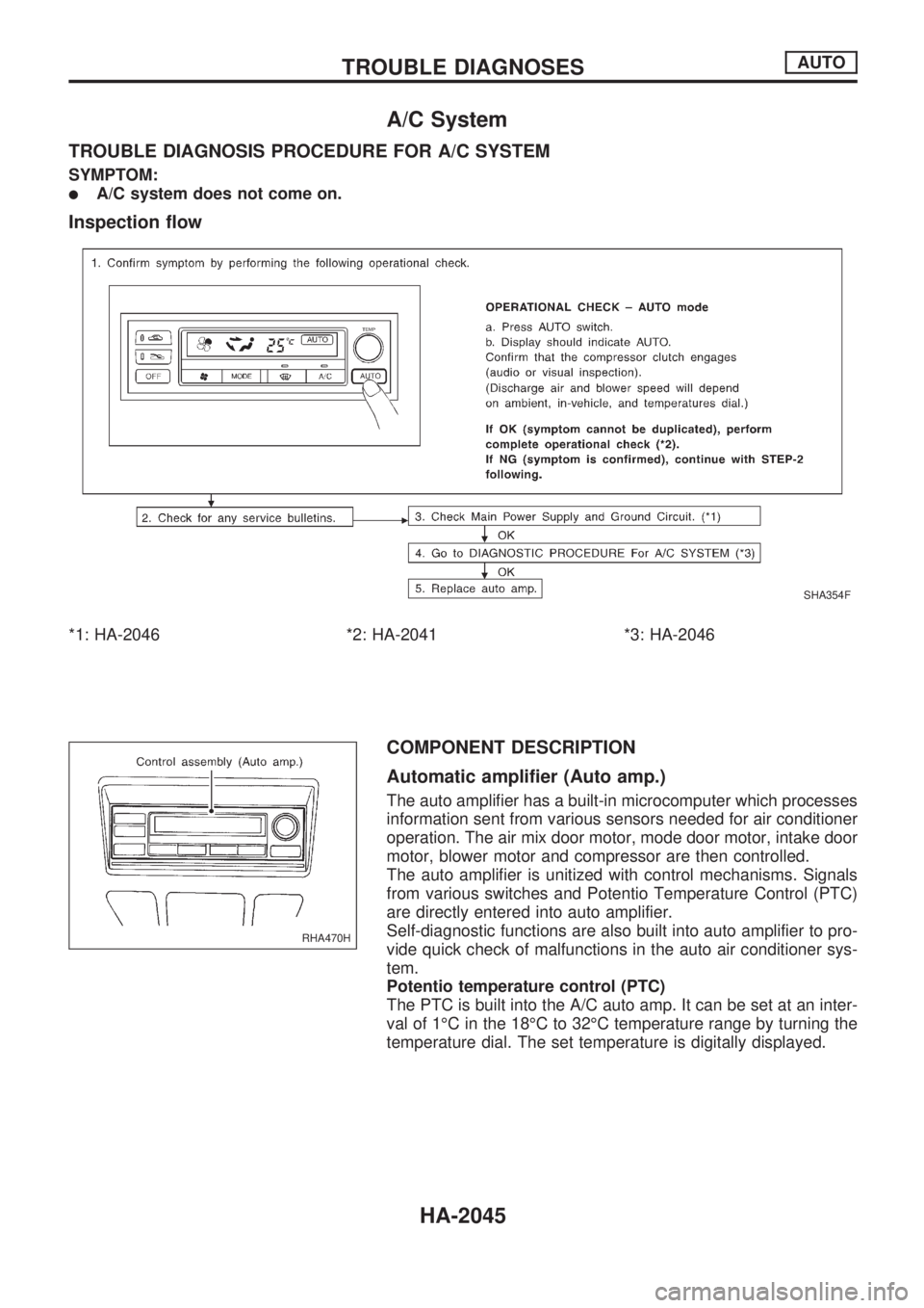
Inspection flow
*1: HA-2046 *2: HA-2041 *3: HA-2046
COMPONENT DESCRIPTION
Automatic amplifier (Auto amp.)
The auto amplifier has a built-in microcomputer which processes
information sent from various sensors needed for air conditioner
operation. The air mix door motor, mode door motor, intake door
motor, blower motor and compressor are then controlled.
The auto amplifier is unitized with control mechanisms. Signals
from various switches and Potentio Temperature Control (PTC)
are directly entered into auto amplifier.
Self-diagnostic functions are also built into auto amplifier to pro-
vide quick check of malfunctions in the auto air conditioner sys-
tem.
Potentio temperature control (PTC)
The PTC is built into the A/C auto amp. It can be set at an inter-
val of 1ÉC in the 18ÉC to 32ÉC temperature range by turning the
temperature dial. The set temperature is digitally displayed.
SHA354F
RHA470H
TROUBLE DIAGNOSESAUTO
HA-2045
Page 548 of 666
SYSTEM DESCRIPTION
Component parts
Mode door control system components are:
1) Auto amplifier
2) Mode door motor
3) In-vehicle sensor4) Ambient sensor
5) Sunload sensor
6) Intake sensor
System operation
The auto amplifier computes the air outlet conditions according to the ambient temperature and the in-ve-
hicle temperature. The computed outlet conditions are then corrected for sunload to determine air outlet
through which air is discharged into the passenger compartment.
Mode door control specification
COMPONENT DESCRIPTION
The mode door motor is attached to the heater unit. It rotates so
that air is discharged from the outlet set by the auto amplifier.
Motor rotation is conveyed to a link which activates the mode
door.
RHA471H
RHA384H
RHA472H
TROUBLE DIAGNOSESAUTO
Mode Door Motor (Cont'd)
HA-2048
Page 553 of 666
SYSTEM DESCRIPTION
Component parts
Air mix door control system components are:
1) Auto amplifier
2) Air mix door motor (PBR)
3) In-vehicle sensor4) Ambient sensor
5) Sunload sensor
6) Intake sensor
System operation
Temperature set by Potentio Temperature Control (PTC) is compensated through setting temperature cor-
rection circuit to determine target temperature.
Auto amplifier will operate air mix door motor to set air conditioning system in HOT or COLD position,
depending upon relationship between conditions (target temperature, sunload, in-vehicle temperature and
ambient temperature) and conditions (air mix door position and intake air temperature).
When target temperature is set at 18ÉC (65ÉF) or 32ÉC (85ÉF), air mix door opening position is fixed in full
cold position or full hot position.
Air mix door control specification
RHA482H
RHA457H
TROUBLE DIAGNOSESAUTO
Air Mix Door Motor (Cont'd)
HA-2053