Page 145 of 666

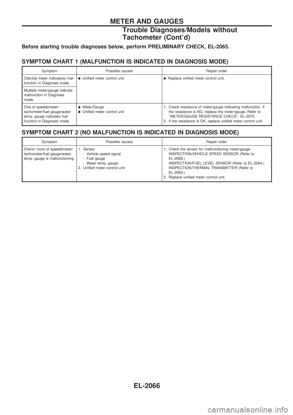
Before starting trouble diagnoses below, perform PRELIMINARY CHECK, EL-2065.
SYMPTOM CHART 1 (MALFUNCTION IS INDICATED IN DIAGNOSIS MODE)
Symptom Possible causes Repair order
Odo/trip meter indicate(s) mal-
function in Diagnosis mode.
lUnified meter control unitlReplace unified meter control unit.
Multiple meter/gauge indicate
malfunction in Diagnosis
mode.
One of speedometer/
tachometer/fuel gauge/water
temp. gauge indicates mal-
function in Diagnosis mode.
lMeter/GaugelUnified meter control unit1. Check resistance of meter/gauge indicating malfunction. If
the resistance is NG, replace the meter/gauge. Refer to
``METER/GAUGE RESISTANCE CHECK'', EL-2070.
2. If the resistance is OK, replace unified meter control unit.
SYMPTOM CHART 2 (NO MALFUNCTION IS INDICATED IN DIAGNOSIS MODE)
Symptom Possible causes Repair order
One/or more of speedometer/
tachometer/fuel gauge/water
temp. gauge is malfunctioning.1. Sensor
- Vehicle speed signal
- Fuel gauge
- Water temp. gauge
2. Unified meter control unit1. Check the sensor for malfunctioning meter/gauge.
INSPECTION/VEHICLE SPEED SENSOR (Refer to
EL-2068.)
INSPECTION/FUEL LEVEL SENSOR (Refer to EL-2064.)
INSPECTION/THERMAL TRANSMITTER (Refer to
EL-2069.)
2. Replace unified meter control unit.
METER AND GAUGES
Trouble Diagnoses/Models without
Tachometer (Cont'd)
EL-2066
Page 147 of 666
INSPECTION/VEHICLE SPEED SENSOR
CHECK VEHICLE SPEED SENSOR
OUTPUT.
1. Remove vehicle speed sensor from
transmission.
2. Check voltage between combination
meter terminals
V24andV37while
quickly turning speed sensor pinion.
Voltage: Approx. 0.5V
NG
cOK
Vehicle speed sensor is
OK.
CHECK VEHICLE SPEED SENSOR.
Check resistance between vehicle speed
sensor terminals
V1andV2.
Resistance: Approx. 250W
OK
cNG
Replace vehicle speed
sensor.
Check harness or connector between
speedometer and vehicle speed sensor.SEL430W
SEL118V
.
.
METER AND GAUGES
Trouble Diagnoses/Models without
Tachometer (Cont'd)
EL-2068
Page 148 of 666

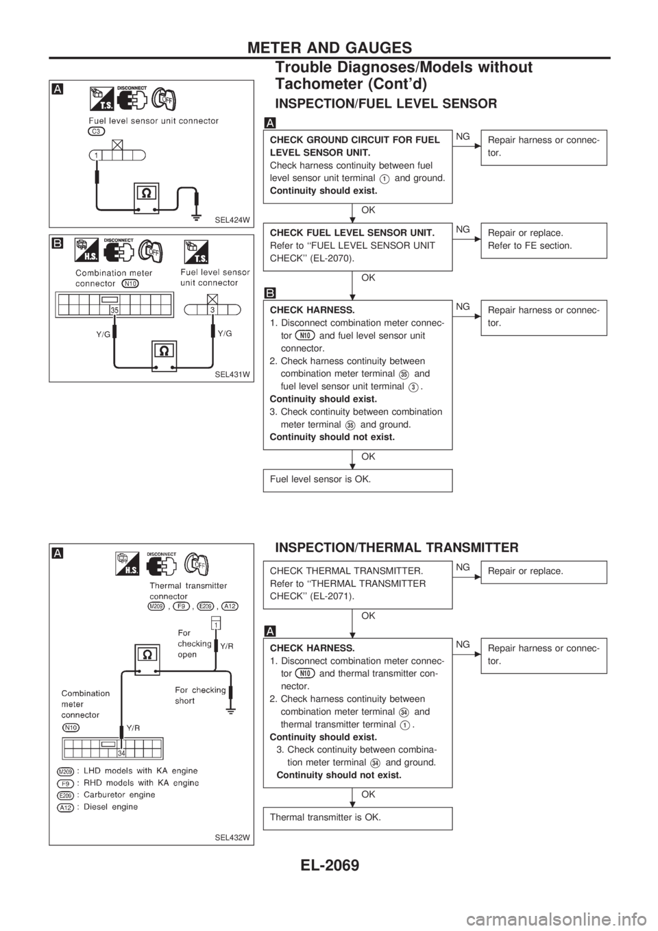
INSPECTION/FUEL LEVEL SENSOR
CHECK GROUND CIRCUIT FOR FUEL
LEVEL SENSOR UNIT.
Check harness continuity between fuel
level sensor unit terminal
V1and ground.
Continuity should exist.
OK
cNG
Repair harness or connec-
tor.
CHECK FUEL LEVEL SENSOR UNIT.
Refer to ``FUEL LEVEL SENSOR UNIT
CHECK'' (EL-2070).
OK
cNG
Repair or replace.
Refer to FE section.
CHECK HARNESS.
1. Disconnect combination meter connec-
tor
N10and fuel level sensor unit
connector.
2. Check harness continuity between
combination meter terminal
V35and
fuel level sensor unit terminal
V3.
Continuity should exist.
3. Check continuity between combination
meter terminal
V35and ground.
Continuity should not exist.
OK
cNG
Repair harness or connec-
tor.
Fuel level sensor is OK.
INSPECTION/THERMAL TRANSMITTER
CHECK THERMAL TRANSMITTER.
Refer to ``THERMAL TRANSMITTER
CHECK'' (EL-2071).
OK
cNG
Repair or replace.
CHECK HARNESS.
1. Disconnect combination meter connec-
tor
N10and thermal transmitter con-
nector.
2. Check harness continuity between
combination meter terminal
V34and
thermal transmitter terminal
V1.
Continuity should exist.
3. Check continuity between combina-
tion meter terminal
V34and ground.
Continuity should not exist.
OK
cNG
Repair harness or connec-
tor.
Thermal transmitter is OK.
SEL424W
SEL431W
SEL432W
.
.
.
.
.
METER AND GAUGES
Trouble Diagnoses/Models without
Tachometer (Cont'd)
EL-2069
Page 149 of 666
Electrical Components Inspection
METER/GAUGE RESISTANCE CHECK
1. Disconnect FPC connector (Combination meter with tachom-
eter). Refer to EL-2059.
2. Check resistance between terminals (the points of installa-
tion screws) of meter/gauge after removing meter/gauge.
Screws
Resistance
W
Tachometer Fuel/Temp. gauge
A - C A - C Approx. 140 - Approx. 260
B - D B - C Approx. 230 - Approx. 310
FUEL LEVEL SENSOR UNIT CHECK
lFor removal, refer to FE section.
Check the resistance between terminals
V1andV3.
Ohmmeter Float position mm (in)
Resistance
value
W (+) (þ)60!(13-1/4
Imp gal) tank80!(17-5/8
Imp gal) tank
V3V1
*1 Full 253 (9.96) 77 (3.03) Approx. 4 - 6
*2 1/2 130 (5.12) 191 (7.52) 27 - 35
*3 Empty 27 (1.06) 299 (11.77) 78 - 85
*1 and *3: When float rod is in contact with stopper.
SEL638W
SEL433W
GEL256
METER AND GAUGES
EL-2070
Page 150 of 666
THERMAL TRANSMITTER CHECK
Check the resistance between the terminals of thermal transmit-
ter and body ground.
Water temperature Resistance
60ÉC (140ÉF) Approx. 167 - 211W
100ÉC (212ÉF) Approx. 47 - 53W
VEHICLE SPEED SENSOR SIGNAL CHECK
1. Remove vehicle speed sensor from transmission.
2. Turn vehicle speed sensor pinion quickly and measure volt-
age between terminals
VaandVb.
MEL424F
SEL378PA
METER AND GAUGES
Electrical Components Inspection (Cont'd)
EL-2071
Page 162 of 666
Electrical Components Inspection
FUEL WARNING LAMP SENSOR CHECK
lIt will take a short time for the bulb to light.
GEL257
WARNING LAMPS
EL-2083
Page 208 of 666

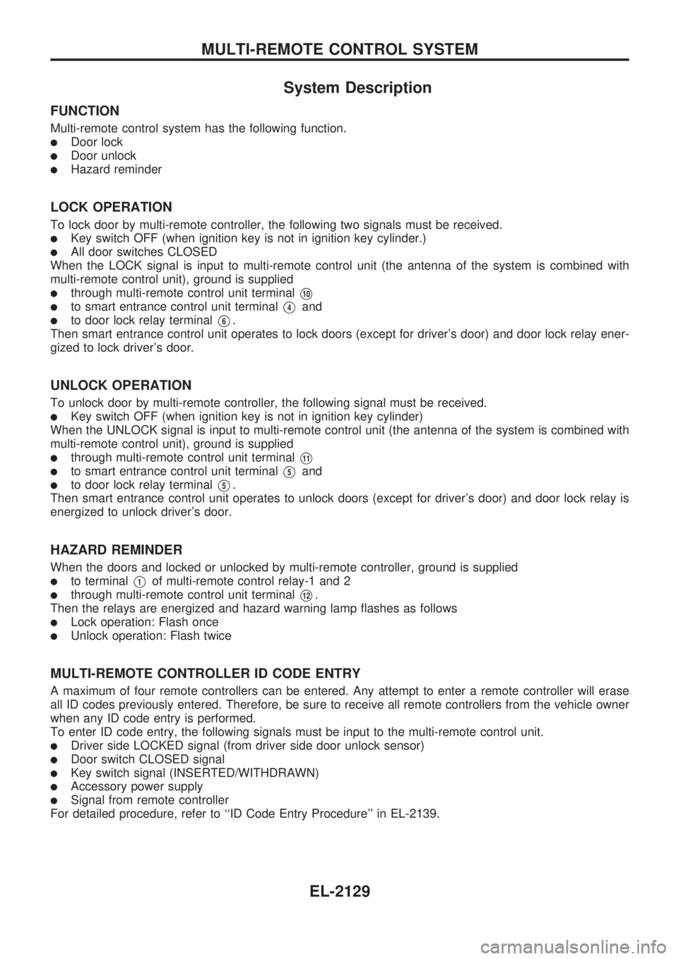
System Description
FUNCTION
Multi-remote control system has the following function.
lDoor lock
lDoor unlock
lHazard reminder
LOCK OPERATION
To lock door by multi-remote controller, the following two signals must be received.
lKey switch OFF (when ignition key is not in ignition key cylinder.)
lAll door switches CLOSED
When the LOCK signal is input to multi-remote control unit (the antenna of the system is combined with
multi-remote control unit), ground is supplied
lthrough multi-remote control unit terminalV10
lto smart entrance control unit terminalV4and
lto door lock relay terminalV6.
Then smart entrance control unit operates to lock doors (except for driver's door) and door lock relay ener-
gized to lock driver's door.
UNLOCK OPERATION
To unlock door by multi-remote controller, the following signal must be received.
lKey switch OFF (when ignition key is not in ignition key cylinder)
When the UNLOCK signal is input to multi-remote control unit (the antenna of the system is combined with
multi-remote control unit), ground is supplied
lthrough multi-remote control unit terminalV11
lto smart entrance control unit terminalV5and
lto door lock relay terminalV5.
Then smart entrance control unit operates to unlock doors (except for driver's door) and door lock relay is
energized to unlock driver's door.
HAZARD REMINDER
When the doors and locked or unlocked by multi-remote controller, ground is supplied
lto terminalV1of multi-remote control relay-1 and 2
lthrough multi-remote control unit terminalV12.
Then the relays are energized and hazard warning lamp flashes as follows
lLock operation: Flash once
lUnlock operation: Flash twice
MULTI-REMOTE CONTROLLER ID CODE ENTRY
A maximum of four remote controllers can be entered. Any attempt to enter a remote controller will erase
all ID codes previously entered. Therefore, be sure to receive all remote controllers from the vehicle owner
when any ID code entry is performed.
To enter ID code entry, the following signals must be input to the multi-remote control unit.
lDriver side LOCKED signal (from driver side door unlock sensor)
lDoor switch CLOSED signal
lKey switch signal (INSERTED/WITHDRAWN)
lAccessory power supply
lSignal from remote controller
For detailed procedure, refer to ``ID Code Entry Procedure'' in EL-2139.
MULTI-REMOTE CONTROL SYSTEM
EL-2129
Page 214 of 666

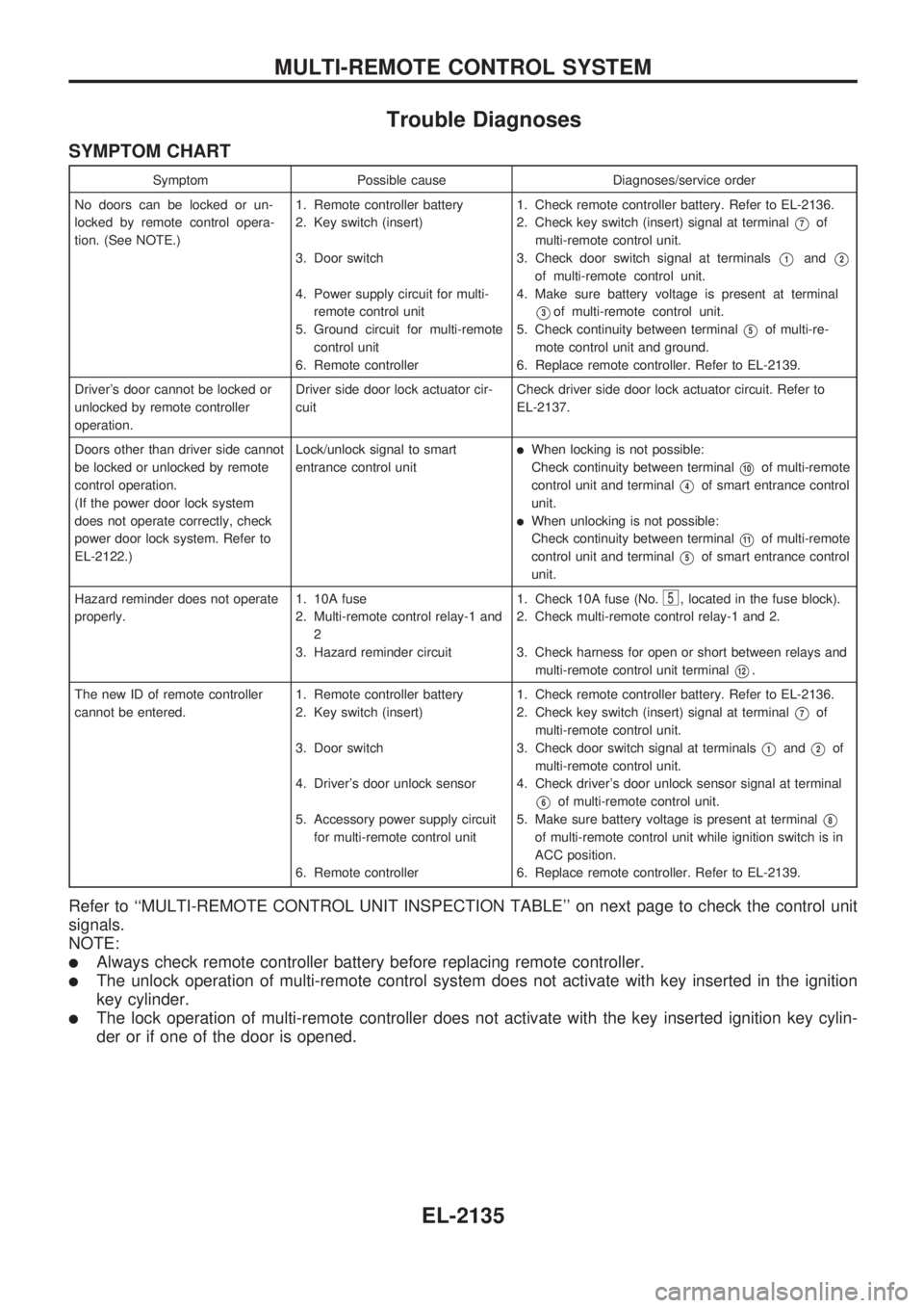
Trouble Diagnoses
SYMPTOM CHART
Symptom Possible cause Diagnoses/service order
No doors can be locked or un-
locked by remote control opera-
tion. (See NOTE.)1. Remote controller battery
2. Key switch (insert)
3. Door switch
4. Power supply circuit for multi-
remote control unit
5. Ground circuit for multi-remote
control unit
6. Remote controller1. Check remote controller battery. Refer to EL-2136.
2. Check key switch (insert) signal at terminal
V7of
multi-remote control unit.
3. Check door switch signal at terminals
V1andV2
of multi-remote control unit.
4. Make sure battery voltage is present at terminal
V3of multi-remote control unit.
5. Check continuity between terminal
V5of multi-re-
mote control unit and ground.
6. Replace remote controller. Refer to EL-2139.
Driver's door cannot be locked or
unlocked by remote controller
operation.Driver side door lock actuator cir-
cuitCheck driver side door lock actuator circuit. Refer to
EL-2137.
Doors other than driver side cannot
be locked or unlocked by remote
control operation.
(If the power door lock system
does not operate correctly, check
power door lock system. Refer to
EL-2122.)Lock/unlock signal to smart
entrance control unit
lWhen locking is not possible:
Check continuity between terminal
V10of multi-remote
control unit and terminal
V4of smart entrance control
unit.
lWhen unlocking is not possible:
Check continuity between terminal
V11of multi-remote
control unit and terminal
V5of smart entrance control
unit.
Hazard reminder does not operate
properly.1. 10A fuse
2. Multi-remote control relay-1 and
2
3. Hazard reminder circuit1. Check 10A fuse (No.
5, located in the fuse block).
2. Check multi-remote control relay-1 and 2.
3. Check harness for open or short between relays and
multi-remote control unit terminal
V12.
The new ID of remote controller
cannot be entered.1. Remote controller battery
2. Key switch (insert)
3. Door switch
4. Driver's door unlock sensor
5. Accessory power supply circuit
for multi-remote control unit
6. Remote controller1. Check remote controller battery. Refer to EL-2136.
2. Check key switch (insert) signal at terminal
V7of
multi-remote control unit.
3. Check door switch signal at terminals
V1andV2of
multi-remote control unit.
4. Check driver's door unlock sensor signal at terminal
V6of multi-remote control unit.
5. Make sure battery voltage is present at terminal
V8
of multi-remote control unit while ignition switch is in
ACC position.
6. Replace remote controller. Refer to EL-2139.
Refer to ``MULTI-REMOTE CONTROL UNIT INSPECTION TABLE'' on next page to check the control unit
signals.
NOTE:
lAlways check remote controller battery before replacing remote controller.
lThe unlock operation of multi-remote control system does not activate with key inserted in the ignition
key cylinder.
lThe lock operation of multi-remote controller does not activate with the key inserted ignition key cylin-
der or if one of the door is opened.
MULTI-REMOTE CONTROL SYSTEM
EL-2135