Page 52 of 666
Camshaft Position Sensor (CMPS)
HEC634
TROUBLE DIAGNOSIS FOR
ªCAMSHAFT POSI SENº (DTC 11)KA24E
EC-2007
Page 53 of 666
Mass Air Flow Sensor (MAFS)
HEC635
TROUBLE DIAGNOSIS FOR
ªMASS AIR FLOW SENº (DTC 12)KA24E
EC-2008
Page 54 of 666
Vehicle Speed Sensor (VSS)
HEC636
TROUBLE DIAGNOSIS FOR NON-DETECTABLE ITEMSKA24E
EC-2009
Page 55 of 666
Heated Oxygen Sensor (HO2S)
Ð LHD Models Ð
HEC637
TROUBLE DIAGNOSIS FOR NON-DETECTABLE ITEMSKA24E
EC-2010
Page 82 of 666

Supplemental Restraint System (SRS) ``AIR
BAG'' and ``SEAT BELT PRE-TENSIONER''
The Supplemental Restraint System such as ``AIR BAG'' and ``SEAT BELT PRE-TENSIONER'' used along
with a seat belt, helps to reduce the risk or severity of injury to the driver and front passenger in a frontal
collision. The SRS system composition which is available to NISSAN MODEL D22 is as follows (The com-
position varies according to the destination and optional equipment.):
Driver air bag module (located in the center of the steering wheel), front passenger air bag module (located
on the instrument panel on passenger side), seat belt pre-tensioner, a diagnosis sensor unit, warning lamp,
wiring harness and spiral cable.
Information necessary to service the system safely is included in theRS sectionof this Service Manual.
WARNING:
lTo avoid rendering the SRS inoperative, which could increase the risk of personal injury or death
in the event of a collision which would result in air bag inflation, all maintenance must be per-
formed by an authorized NISSAN dealer.
lImproper maintenance, including incorrect removal and installation of the SRS, can lead to per-
sonal injury caused by unintentional activation of the system. For removal of Spiral Cable and
Air Bag Module, see the RS section.
lDo not use electrical test equipment on any circuit related to the SRS unless instructed to in this
Service Manual. Spiral Cable and wiring harnesses (except ``SEAT BELT PRE-TENSIONER'')
covered with yellow insulation either just before the harness connectors or for the complete har-
ness are related to the SRS.
PRECAUTIONS
EL-2003
Page 140 of 666

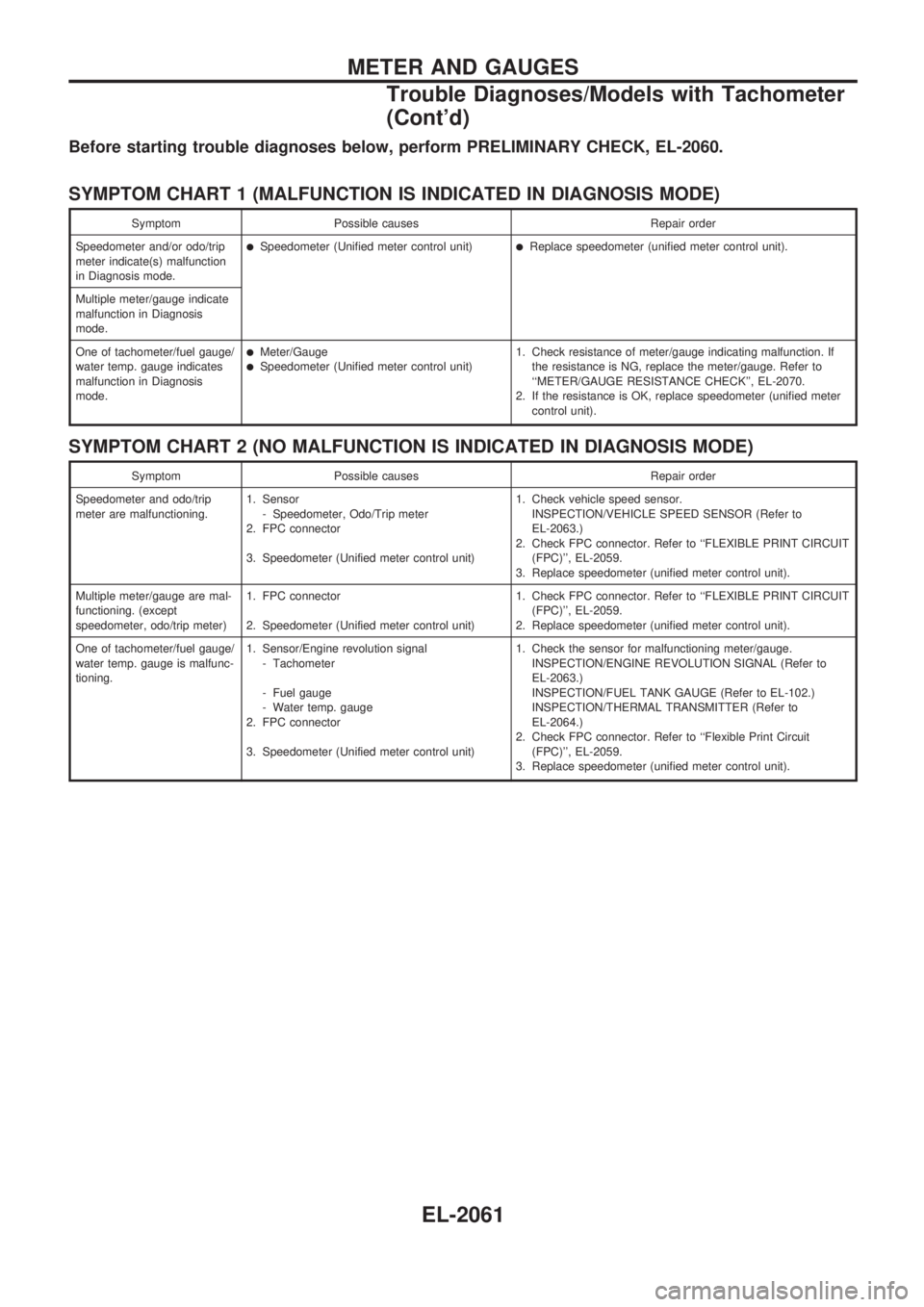
Before starting trouble diagnoses below, perform PRELIMINARY CHECK, EL-2060.
SYMPTOM CHART 1 (MALFUNCTION IS INDICATED IN DIAGNOSIS MODE)
Symptom Possible causes Repair order
Speedometer and/or odo/trip
meter indicate(s) malfunction
in Diagnosis mode.
lSpeedometer (Unified meter control unit)lReplace speedometer (unified meter control unit).
Multiple meter/gauge indicate
malfunction in Diagnosis
mode.
One of tachometer/fuel gauge/
water temp. gauge indicates
malfunction in Diagnosis
mode.
lMeter/GaugelSpeedometer (Unified meter control unit)1. Check resistance of meter/gauge indicating malfunction. If
the resistance is NG, replace the meter/gauge. Refer to
``METER/GAUGE RESISTANCE CHECK'', EL-2070.
2. If the resistance is OK, replace speedometer (unified meter
control unit).
SYMPTOM CHART 2 (NO MALFUNCTION IS INDICATED IN DIAGNOSIS MODE)
Symptom Possible causes Repair order
Speedometer and odo/trip
meter are malfunctioning.1. Sensor
- Speedometer, Odo/Trip meter
2. FPC connector
3. Speedometer (Unified meter control unit)1. Check vehicle speed sensor.
INSPECTION/VEHICLE SPEED SENSOR (Refer to
EL-2063.)
2. Check FPC connector. Refer to ``FLEXIBLE PRINT CIRCUIT
(FPC)'', EL-2059.
3. Replace speedometer (unified meter control unit).
Multiple meter/gauge are mal-
functioning. (except
speedometer, odo/trip meter)1. FPC connector
2. Speedometer (Unified meter control unit)1. Check FPC connector. Refer to ``FLEXIBLE PRINT CIRCUIT
(FPC)'', EL-2059.
2. Replace speedometer (unified meter control unit).
One of tachometer/fuel gauge/
water temp. gauge is malfunc-
tioning.1. Sensor/Engine revolution signal
- Tachometer
- Fuel gauge
- Water temp. gauge
2. FPC connector
3. Speedometer (Unified meter control unit)1. Check the sensor for malfunctioning meter/gauge.
INSPECTION/ENGINE REVOLUTION SIGNAL (Refer to
EL-2063.)
INSPECTION/FUEL TANK GAUGE (Refer to EL-102.)
INSPECTION/THERMAL TRANSMITTER (Refer to
EL-2064.)
2. Check FPC connector. Refer to ``Flexible Print Circuit
(FPC)'', EL-2059.
3. Replace speedometer (unified meter control unit).
METER AND GAUGES
Trouble Diagnoses/Models with Tachometer
(Cont'd)
EL-2061
Page 142 of 666

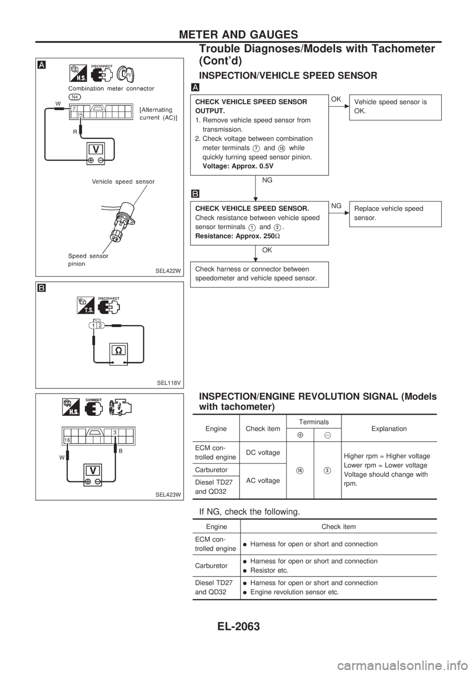
INSPECTION/VEHICLE SPEED SENSOR
CHECK VEHICLE SPEED SENSOR
OUTPUT.
1. Remove vehicle speed sensor from
transmission.
2. Check voltage between combination
meter terminals
V7andV15while
quickly turning speed sensor pinion.
Voltage: Approx. 0.5V
NG
cOK
Vehicle speed sensor is
OK.
CHECK VEHICLE SPEED SENSOR.
Check resistance between vehicle speed
sensor terminals
V1andV2.
Resistance: Approx. 250W
OK
cNG
Replace vehicle speed
sensor.
Check harness or connector between
speedometer and vehicle speed sensor.
INSPECTION/ENGINE REVOLUTION SIGNAL (Models
with tachometer)
Engine Check itemTerminals
ExplanationÅ@
ECM con-
trolled engineDC voltage
V16V3
Higher rpm = Higher voltage
Lower rpm = Lower voltage
Voltage should change with
rpm. Carburetor
AC voltage
Diesel TD27
and QD32
If NG, check the following.
Engine Check item
ECM con-
trolled engine
lHarness for open or short and connection
Carburetor
lHarness for open or short and connection
lResistor etc.
Diesel TD27
and QD32
lHarness for open or short and connection
lEngine revolution sensor etc.
SEL422W
SEL118V
SEL423W
.
.
METER AND GAUGES
Trouble Diagnoses/Models with Tachometer
(Cont'd)
EL-2063
Page 143 of 666

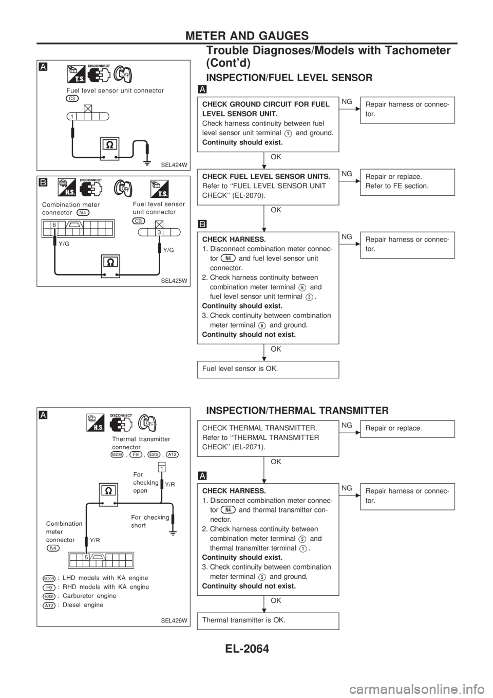
INSPECTION/FUEL LEVEL SENSOR
CHECK GROUND CIRCUIT FOR FUEL
LEVEL SENSOR UNIT.
Check harness continuity between fuel
level sensor unit terminal
V1and ground.
Continuity should exist.
OK
cNG
Repair harness or connec-
tor.
CHECK FUEL LEVEL SENSOR UNITS.
Refer to ``FUEL LEVEL SENSOR UNIT
CHECK'' (EL-2070).
OK
cNG
Repair or replace.
Refer to FE section.
CHECK HARNESS.
1. Disconnect combination meter connec-
tor
N4and fuel level sensor unit
connector.
2. Check harness continuity between
combination meter terminal
V6and
fuel level sensor unit terminal
V3.
Continuity should exist.
3. Check continuity between combination
meter terminal
V6and ground.
Continuity should not exist.
OK
cNG
Repair harness or connec-
tor.
Fuel level sensor is OK.
INSPECTION/THERMAL TRANSMITTER
CHECK THERMAL TRANSMITTER.
Refer to ``THERMAL TRANSMITTER
CHECK'' (EL-2071).
OK
cNG
Repair or replace.
CHECK HARNESS.
1. Disconnect combination meter connec-
tor
N4and thermal transmitter con-
nector.
2. Check harness continuity between
combination meter terminal
V5and
thermal transmitter terminal
V1.
Continuity should exist.
3. Check continuity between combination
meter terminal
V5and ground.
Continuity should not exist.
OK
cNG
Repair harness or connec-
tor.
Thermal transmitter is OK.
SEL424W
SEL425W
SEL426W
.
.
.
.
.
METER AND GAUGES
Trouble Diagnoses/Models with Tachometer
(Cont'd)
EL-2064