1999 NISSAN PICK-UP sensor
[x] Cancel search: sensorPage 3 of 666
BRAKESYSTEM
SECTION
BR
MODIFICATION NOTICE:
lWiring Diagrams have been changed.
lService data and specifications (SDS) has been changed.
CONTENTS
TROUBLE DIAGNOSES ..................................... 2002
Component Parts and Harness Connector
Location............................................................ 2002
Schematic/2WD Models................................... 2003
Wiring Diagram - ABS -/2WD LHD Models ..... 2004
Wiring Diagram - ABS -/2WD RHD Models .... 2007
Schematic/4WD Models................................... 2010
Wiring Diagram - ABS -/4WD LHD Models ..... 2011
Wiring Diagram - ABS -/4WD RHD Models .... 2015
TROUBLE DIAGNOSES FOR
SELF-DIAGNOSTIC ITEMS ................................ 2019
Diagnostic Procedure 1 (Wheel sensor or
rotor)................................................................. 2019
Diagnostic Procedure 2 (ABS actuator
solenoid valve and solenoid valve relay)......... 2021 Diagnostic Procedure 3 (Motor relay o
rmotor).............................................................. 2023
Diagnostic Procedure 4 (Low voltage) ............ 2025
Diagnostic Procedure 5 (G sensor) ................. 2026
Diagnostic Procedure 6 (Control unit) ............. 2027
TROUBLE DIAGNOSES FOR SYMPTOMS ....... 2028
Diagnostic Procedure 12 (Warning lamp does
not come on when ignition switch is turned
ON.).................................................................. 2028
Diagnostic Procedure 13 (Warning lamp stays
on when ignition switch is turned ON.)............ 2030
SERVICE DATA AND SPECIFICATIONS
(SDS) .................................................................... 2031
General Specifications ..................................... 2031
BR
Page 21 of 666
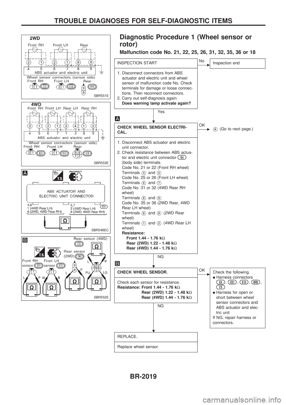
Diagnostic Procedure 1 (Wheel sensor or
rotor)
Malfunction code No. 21, 22, 25, 26, 31, 32, 35, 36 or 18
INSPECTION START
-------------------------------------------------------------------------------------------------------------------------------------------------------------------------------------------------------------------------------------------------------------------------------------------------------------
1. Disconnect connectors from ABS
actuator and electric unit and wheel
sensor of malfunction code No. Check
terminals for damage or loose connec-
tions. Then reconnect connectors.
2. Carry out self-diagnosis again.
Does warning lamp activate again?
Yes
cNo
Inspection end
CHECK WHEEL SENSOR ELECTRI-
CAL.
-------------------------------------------------------------------------------------------------------------------------------------------------------------------------------------------------------------------------------------------------------------------------------------------------------------
1. Disconnect ABS actuator and electric
unit connector.
2. Check resistance between ABS actua-
tor and electric unit connector
E4
(body side) terminals.
Code No. 21 or 22 (Front RH wheel)
Terminals
V4andV5
Code No. 25 or 26 (Front LH wheel)
Terminals
V6andV7
Code No. 31 or 32 (4WD Rear RH
wheel)
Terminals
V8andV9
Code No. 35 or 36 (2WD Rear, 4WD
Rear LH wheel)
Terminals
V8andV9(2WD Rear
wheel)
Terminals
V1andV2(4WD Rear LH
wheel)
Resistance:
Front 1.44 - 1.76 kW
Rear (2WD) 1.22 - 1.48 kW
Rear (4WD) 1.44 - 1.76 kW
NG
cOKVA(Go to next page.)
CHECK WHEEL SENSOR.
-------------------------------------------------------------------------------------------------------------------------------------------------------------------------------------------------------------------------------------------------------------------------------------------------------------
Check each sensor for resistance.
Resistance: Front 1.44 - 1.76 kW
Rear (2WD) 1.22 - 1.48 kW
Rear (4WD) 1.44 - 1.76 kW
NG
cOK
Check the following.
lHarness connectorsE4,E31,E15,BR5,C5
lHarness for open or
short between wheel
sensor connectors and
ABS actuator and elec-
tric unit
If NG, repair harness or
connectors.
REPLACE.
-------------------------------------------------------------------------------------------------------------------------------------------------------------------------------------------------------------------------------------------------------------------------------------------------------------
Replace wheel sensor.
SBR551E
SBR553E
SBR048EC
SBR552E
.
.
.
TROUBLE DIAGNOSES FOR SELF-DIAGNOSTIC ITEMS
BR-2019
Page 22 of 666
VA
Note
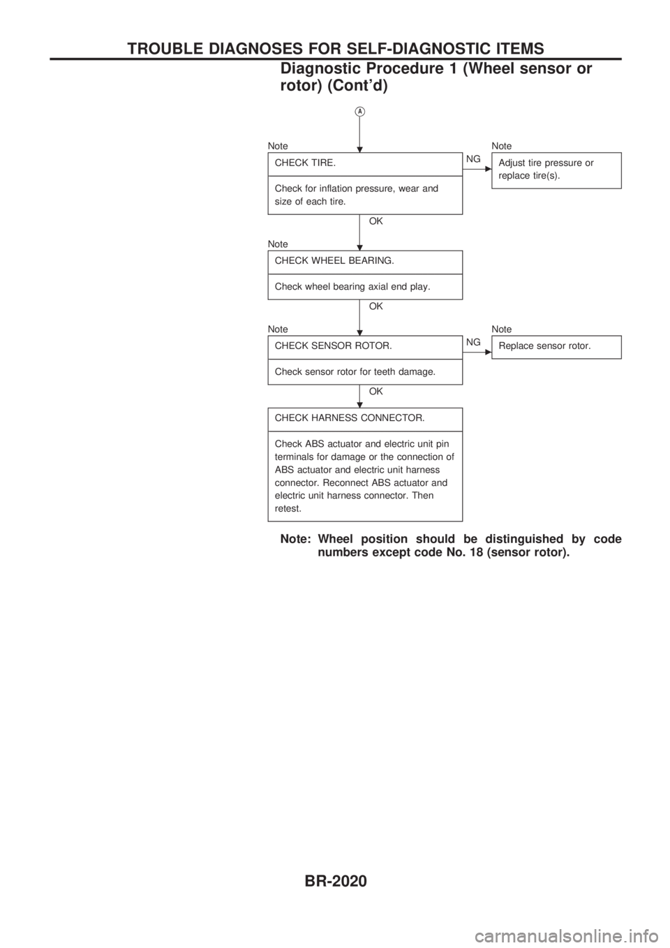
CHECK TIRE.
-------------------------------------------------------------------------------------------------------------------------------------------------------------------------------------------------------------------------------------------------------------------------------------------------------------
Check for inflation pressure, wear and
size of each tire.
OK
cNGNote
Adjust tire pressure or
replace tire(s).
Note
CHECK WHEEL BEARING.
-------------------------------------------------------------------------------------------------------------------------------------------------------------------------------------------------------------------------------------------------------------------------------------------------------------
Check wheel bearing axial end play.
OK
Note
CHECK SENSOR ROTOR.
-------------------------------------------------------------------------------------------------------------------------------------------------------------------------------------------------------------------------------------------------------------------------------------------------------------
Check sensor rotor for teeth damage.
OK
cNGNote
Replace sensor rotor.
CHECK HARNESS CONNECTOR.
-------------------------------------------------------------------------------------------------------------------------------------------------------------------------------------------------------------------------------------------------------------------------------------------------------------
Check ABS actuator and electric unit pin
terminals for damage or the connection of
ABS actuator and electric unit harness
connector. Reconnect ABS actuator and
electric unit harness connector. Then
retest.
Note: Wheel position should be distinguished by code
numbers except code No. 18 (sensor rotor).
.
.
.
.
TROUBLE DIAGNOSES FOR SELF-DIAGNOSTIC ITEMS
Diagnostic Procedure 1 (Wheel sensor or
rotor) (Cont'd)
BR-2020
Page 28 of 666

Diagnostic Procedure 5 (G sensor)
Malfunction code No. 17
CHECK G SENSOR POWER SUPPLY
CIRCUIT.
-------------------------------------------------------------------------------------------------------------------------------------------------------------------------------------------------------------------------------------------------------------------------------------------------------------
Check 10A fuse
18. For fuse layout, refer
to POWER SUPPLY ROUTING in EL sec-
tion.
OK
cNG
Replace fuse.
CHECK CONNECTOR.
-------------------------------------------------------------------------------------------------------------------------------------------------------------------------------------------------------------------------------------------------------------------------------------------------------------
1. Disconnect ABS actuator and electric
unit connector. Check terminals for
damage or loose connection. Then
reconnect connector.
2. Carry out self-diagnosis again.
Does warning lamp activate again?
Yes
cNo
Inspection end
CHECK G SENSOR.
-------------------------------------------------------------------------------------------------------------------------------------------------------------------------------------------------------------------------------------------------------------------------------------------------------------
Refer to G SENSOR in Electrical Compo-
nents Inspection, BR-2027.
OK
cNG
Replace G sensor.
CHECK G SENSOR POWER SUPPLY
CIRCUIT.
-------------------------------------------------------------------------------------------------------------------------------------------------------------------------------------------------------------------------------------------------------------------------------------------------------------
1. Disconnect G sensor connector.
2. Check voltage between G sensor con-
nector
M101,M102(body side) terminal
V2,V15and ground.
Battery voltage should exist.
OK
cNG
Check the following.
lHarness connectors
M101,M102,E4
lHarness for open or short
between G sensor and
ABS actuator and electric
unit
If NG, repair harness or
connectors.
CHECK G SENSOR GROUND.
-------------------------------------------------------------------------------------------------------------------------------------------------------------------------------------------------------------------------------------------------------------------------------------------------------------
1. Disconnect ABS actuator and electric
unit connector and G sensor connec-
tors.
2. Check continuity between ABS actuator
and electric unit connector
E4(body
side) terminals
V10,V20and G sensor
connectors
M101,M102(body side) ter-
minals
V10,V20.
Continuity should exist.
OK
cNG
Check the following.
lHarness connectors
M101,M102,E4
lHarness for open or short
between G sensor and
ABS actuator and electric
unit
If NG, repair harness or
connectors.
CHECK HARNESS CONNECTOR.
-------------------------------------------------------------------------------------------------------------------------------------------------------------------------------------------------------------------------------------------------------------------------------------------------------------
Check ABS actuator and electric unit pin
terminals for damage or the connection of
ABS actuator and electric unit harness
connector. Reconnect ABS actuator and
electric unit harness connector. Then
retest.
SBR059EA
SBR060E
SBR061E
.
.
.
.
.
TROUBLE DIAGNOSES FOR SELF-DIAGNOSTIC ITEMS
BR-2026
Page 29 of 666
ELECTRICAL COMPONENTS INSPECTION
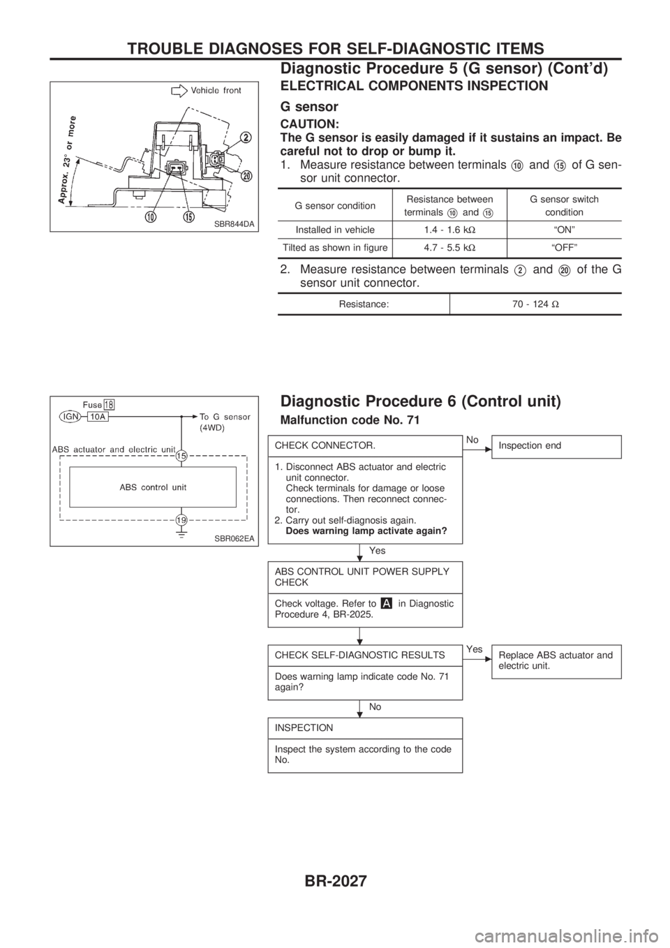
G sensor
CAUTION:
The G sensor is easily damaged if it sustains an impact. Be
careful not to drop or bump it.
1. Measure resistance between terminals
V10andV15of G sen-
sor unit connector.
G sensor conditionResistance between
terminalsV10andV15
G sensor switch
condition
Installed in vehicle 1.4 - 1.6 kWªONº
Tilted as shown in figure 4.7 - 5.5 kWªOFFº
2. Measure resistance between terminalsV2andV20of the G
sensor unit connector.
Resistance: 70 - 124W
Diagnostic Procedure 6 (Control unit)
Malfunction code No. 71
CHECK CONNECTOR.
-------------------------------------------------------------------------------------------------------------------------------------------------------------------------------------------------------------------------------------------------------------------------------------------------------------
1. Disconnect ABS actuator and electric
unit connector.
Check terminals for damage or loose
connections. Then reconnect connec-
tor.
2. Carry out self-diagnosis again.
Does warning lamp activate again?
Yes
cNo
Inspection end
ABS CONTROL UNIT POWER SUPPLY
CHECK
-------------------------------------------------------------------------------------------------------------------------------------------------------------------------------------------------------------------------------------------------------------------------------------------------------------
Check voltage. Refer to
in Diagnostic
Procedure 4, BR-2025.
CHECK SELF-DIAGNOSTIC RESULTS
-------------------------------------------------------------------------------------------------------------------------------------------------------------------------------------------------------------------------------------------------------------------------------------------------------------
Does warning lamp indicate code No. 71
again?
No
cYes
Replace ABS actuator and
electric unit.
INSPECTION
-------------------------------------------------------------------------------------------------------------------------------------------------------------------------------------------------------------------------------------------------------------------------------------------------------------
Inspect the system according to the code
No.
SBR844DA
SBR062EA
.
.
.
TROUBLE DIAGNOSES FOR SELF-DIAGNOSTIC ITEMS
Diagnostic Procedure 5 (G sensor) (Cont'd)
BR-2027
Page 35 of 666
Supplemental Restraint System (SRS) ``AIR
BAG'' and ``SEAT BELT PRE-TENSIONER''
The Supplemental Restraint System such as ªAIR BAGº and ªSEAT BELT PRE-TENSIONERº used along
with a seat belt, helps to reduce the risk or severity of injury to the driver and front passenger in a frontal
collision. The SRS system composition which is available to NISSAN MODEL D22 is as follows (The com-
position varies according to the destination and optional equipment.):
Driver air bag module (located in the center of the steering wheel), front passenger air bag module (located
on the instrument panel on passenger side), seat belt pre-tensioner, a diagnosis sensor unit, warning lamp,
wiring harness and spiral cable.
Information necessary to service the system safely is included in theRS sectionof this Service Manual.
WARNING:
lTo avoid rendering the SRS inoperative, which could increase the risk of personal injury or death
in the event of a collision which would result in air bag inflation, all maintenance must be per-
formed by an authorized NISSAN dealer.
lImproper maintenance, including incorrect removal and installation of the SRS, can lead to per-
sonal injury caused by unintentional activation of the system. For removal of Spiral Cable and
Air Bag Module, see the RS section.
lDo not use electrical test equipment on any circuit related to the SRS unless instructed to in this
Service Manual. Spiral Cable and wiring harnesses (except ªSEAT BELT PRE-TENSIONERº) cov-
ered with yellow insulation either just before the harness connectors or for the complete harness
are related to the SRS.
PRECAUTIONS
BT-2002
Page 46 of 666
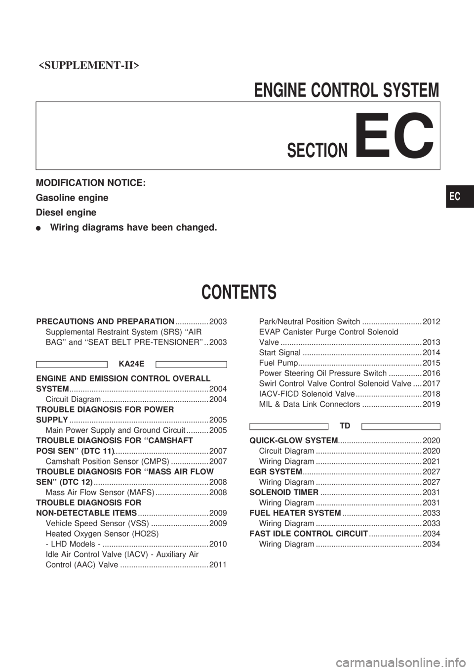
ENGINECONTROLSYSTEM
SECTION
EC
MODIFICATION NOTICE:
Gasoline engine
Diesel engine
lWiring diagrams have been changed.
CONTENTS
PRECAUTIONS AND PREPARATION ............... 2003
Supplemental Restraint System (SRS) ``AIR
BAG'' and ``SEAT BELT PRE-TENSIONER'' .. 2003
KA24E
ENGINE AND EMISSION CONTROL OVERALL
SYSTEM............................................................... 2004
Circuit Diagram ................................................ 2004
TROUBLE DIAGNOSIS FOR POWER
SUPPLY ............................................................... 2005
Main Power Supply and Ground Circuit .......... 2005
TROUBLE DIAGNOSIS FOR ``CAMSHAFT
POSI SEN'' (DTC 11) ........................................... 2007
Camshaft Position Sensor (CMPS) ................. 2007
TROUBLE DIAGNOSIS FOR ``MASS AIR FLOW
SEN'' (DTC 12) .................................................... 2008
Mass Air Flow Sensor (MAFS) ........................ 2008
TROUBLE DIAGNOSIS FOR
NON-DETECTABLE ITEMS ................................ 2009
Vehicle Speed Sensor (VSS) .......................... 2009
Heated Oxygen Sensor (HO2S)
- LHD Models - ................................................ 2010
Idle Air Control Valve (IACV) - Auxiliary Air
Control (AAC) Valve ........................................ 2011 Park/Neutral Position Switch ........................... 2012
EVAP Canister Purge Control Solenoid
Valve ................................................................ 2013
Start Signal ...................................................... 2014
Fuel Pump........................................................ 2015
Power Steering Oil Pressure Switch ............... 2016
Swirl Control Valve Control Solenoid Valve .... 2017
IACV-FICD Solenoid Valve .............................. 2018
MIL & Data Link Connectors ........................... 2019
TD
QUICK-GLOW SYSTEM ...................................... 2020
Circuit Diagram ................................................ 2020
Wiring Diagram ................................................ 2021
EGR SYSTEM ...................................................... 2027
Wiring Diagram ................................................ 2027
SOLENOID TIMER .............................................. 2031
Wiring Diagram ................................................ 2031
FUEL HEATER SYSTEM .................................... 2033
Wiring Diagram ................................................ 2033
FAST IDLE CONTROL CIRCUIT ........................ 2034
Wiring Diagram ................................................ 2034
EC
Page 48 of 666
Supplemental Restraint System (SRS) ªAIR
BAGº and ªSEAT BELT PRE-TENSIONERº
The Supplemental Restraint System such as ªAIR BAGº and ªSEAT BELT PRE-TENSIONERº used along
with a seat belt, helps to reduce the risk or severity of injury to the driver and front passenger in a frontal
collision. The SRS system composition which is available to NISSAN MODEL D22 is as follows (The com-
position varies according to the destination and optional equipment.):
Driver air bag module (located in the center of the steering wheel), front passenger air bag module (located
on the instrument panel on passenger side), seat belt pre-tensioner, a diagnosis sensor unit, warning lamp,
wiring harness and spiral cable.
Information necessary to service the system safely is included in theRS sectionof this Service Manual.
WARNING:
lTo avoid rendering the SRS inoperative, which could increase the risk of personal injury or death
in the event of a collision which would result in air bag inflation, all maintenance must be per-
formed by an authorized NISSAN dealer.
lImproper maintenance, including incorrect removal and installation of the SRS, can lead to per-
sonal injury caused by unintentional activation of the system. For removal of Spiral Cable and
Air Bag Module, see the RS section.
lDo not use electrical test equipment on any circuit related to the SRS unless instructed to in this
Service Manual. Spiral Cable and wiring harnesses (except ªSEAT BELT PRE-TENSIONERº) cov-
ered with yellow insulation either just before the harness connectors or for the complete harness
are related to the SRS.
PRECAUTIONS AND PREPARATION
EC-2003