1999 NISSAN PICK-UP check oil
[x] Cancel search: check oilPage 438 of 666
Measurement of Compression Pressure
1. Warm up engine.
2. Turn ignition switch OFF.
3. Release fuel pressure.
Refer to EC section (ªFuel Pressure Releaseº, ªBASIC SER-
VICE PROCEDUREº).
4. Remove all spark plugs.
lClean area around the plug with compressed air before
removing the spark plug.
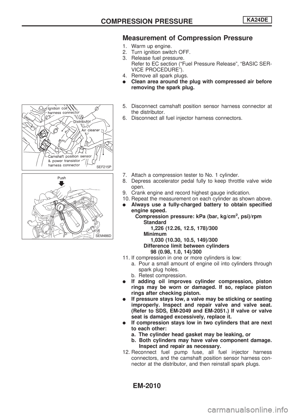
5. Disconnect camshaft position sensor harness connector at
the distributor.
6. Disconnect all fuel injector harness connectors.
7. Attach a compression tester to No. 1 cylinder.
8. Depress accelerator pedal fully to keep throttle valve wide
open.
9. Crank engine and record highest gauge indication.
10. Repeat the measurement on each cylinder as shown above.
lAlways use a fully-charged battery to obtain specified
engine speed.
Compression pressure: kPa (bar, kg/cm
2, psi)/rpm
Standard
1,226 (12.26, 12.5, 178)/300
Minimum
1,030 (10.30, 10.5, 149)/300
Difference limit between cylinders
98 (0.98, 1.0, 14)/300
11. If compression in one or more cylinders is low:
a. Pour a small amount of engine oil into cylinders through
spark plug holes.
b. Retest compression.
lIf adding oil improves cylinder compression, piston
rings may be worn or damaged. If so, replace piston
rings after checking piston.
lIf pressure stays low, a valve may be sticking or seating
improperly. Inspect and repair valve and valve seat.
(Refer to SDS, EM-2049 and EM-2051.) If valve or valve
seat is damaged excessively, replace it.
lIf compression stays low in two cylinders that are next
to each other:
a. The cylinder head gasket may be leaking, or
b. Both cylinders may have valve component damage.
Inspect and repair as necessary.
12. Reconnect fuel pump fuse, all fuel injector harness
connectors, and the camshaft position sensor harness con-
nector at the distributor, and then reinstall spark plugs.
SEF215P
SEM486D
COMPRESSION PRESSUREKA24DE
EM-2010
Page 445 of 666
8. Remove oil pan.
lRefer to ªRemovalº in ªOIL PANº (EM-2011).
9. Remove the oil pump and distributor drive shaft, then the oil
pickup strainer.
10. Remove the front cover.
CAUTION:
Be careful not to tear or damage the cylinder head gasket.
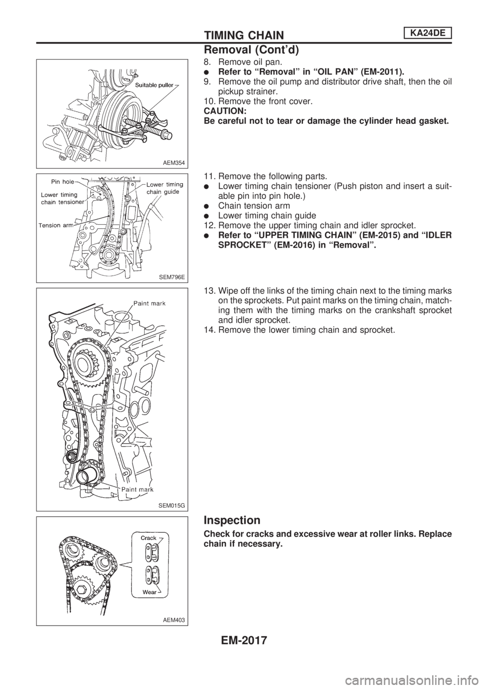
11. Remove the following parts.
lLower timing chain tensioner (Push piston and insert a suit-
able pin into pin hole.)
lChain tension arm
lLower timing chain guide
12. Remove the upper timing chain and idler sprocket.
lRefer to ªUPPER TIMING CHAINº (EM-2015) and ªIDLER
SPROCKETº (EM-2016) in ªRemovalº.
13. Wipe off the links of the timing chain next to the timing marks
on the sprockets. Put paint marks on the timing chain, match-
ing them with the timing marks on the crankshaft sprocket
and idler sprocket.
14. Remove the lower timing chain and sprocket.
Inspection
Check for cracks and excessive wear at roller links. Replace
chain if necessary.
AEM354
SEM796E
SEM015G
AEM403
TIMING CHAINKA24DE
Removal (Cont'd)
EM-2017
Page 454 of 666
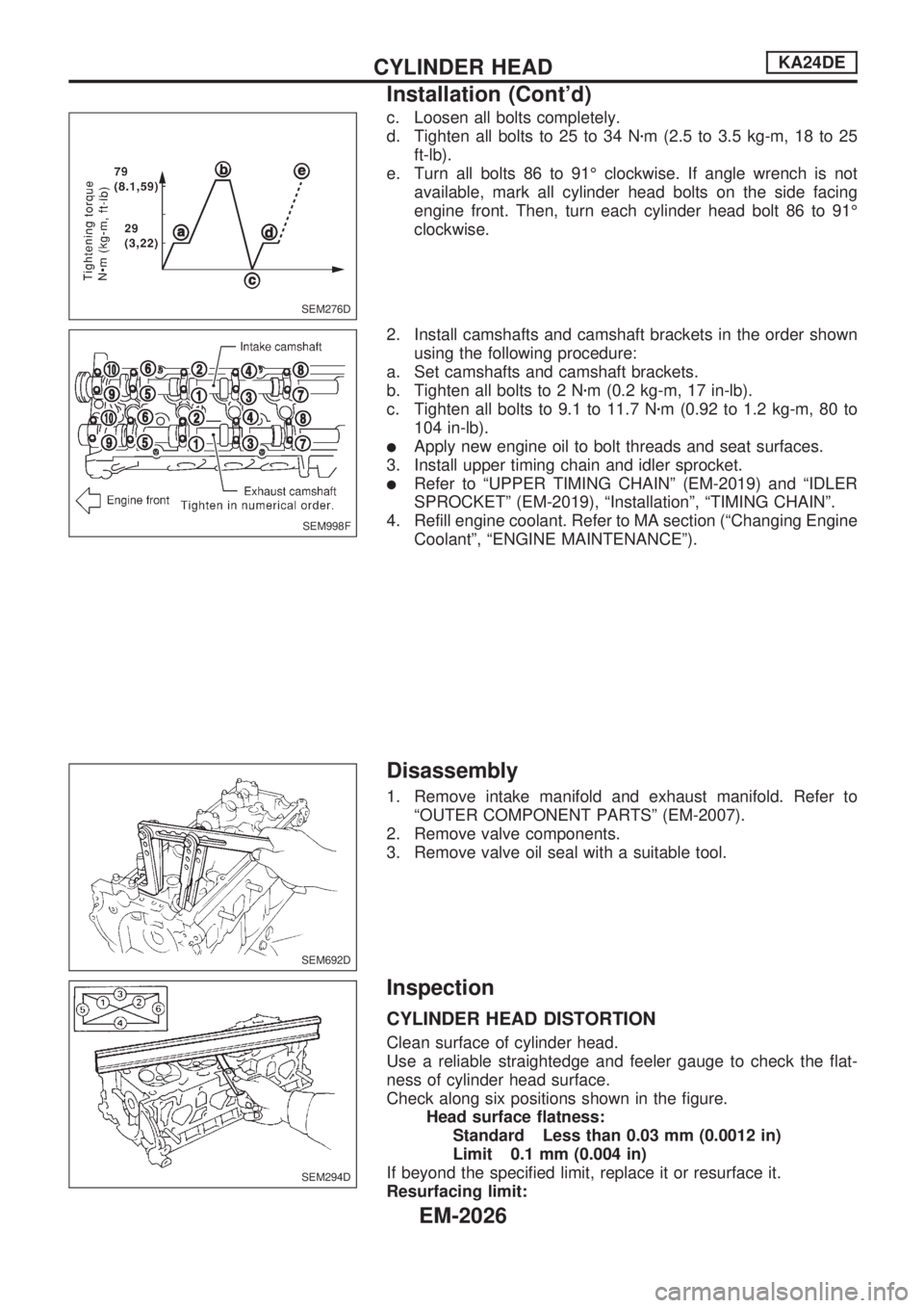
c. Loosen all bolts completely.
d. Tighten all bolts to 25 to 34 Nzm (2.5 to 3.5 kg-m, 18 to 25
ft-lb).
e. Turn all bolts 86 to 91É clockwise. If angle wrench is not
available, mark all cylinder head bolts on the side facing
engine front. Then, turn each cylinder head bolt 86 to 91É
clockwise.
2. Install camshafts and camshaft brackets in the order shown
using the following procedure:
a. Set camshafts and camshaft brackets.
b. Tighten all bolts to 2 Nzm (0.2 kg-m, 17 in-lb).
c. Tighten all bolts to 9.1 to 11.7 Nzm (0.92 to 1.2 kg-m, 80 to
104 in-lb).
lApply new engine oil to bolt threads and seat surfaces.
3. Install upper timing chain and idler sprocket.
lRefer to ªUPPER TIMING CHAINº (EM-2019) and ªIDLER
SPROCKETº (EM-2019), ªInstallationº, ªTIMING CHAINº.
4. Refill engine coolant. Refer to MA section (ªChanging Engine
Coolantº, ªENGINE MAINTENANCEº).
Disassembly
1. Remove intake manifold and exhaust manifold. Refer to
ªOUTER COMPONENT PARTSº (EM-2007).
2. Remove valve components.
3. Remove valve oil seal with a suitable tool.
Inspection
CYLINDER HEAD DISTORTION
Clean surface of cylinder head.
Use a reliable straightedge and feeler gauge to check the flat-
ness of cylinder head surface.
Check along six positions shown in the figure.
Head surface flatness:
Standard Less than 0.03 mm (0.0012 in)
Limit 0.1 mm (0.004 in)
If beyond the specified limit, replace it or resurface it.
Resurfacing limit:
SEM276D
SEM998F
SEM692D
SEM294D
CYLINDER HEADKA24DE
Installation (Cont'd)
EM-2026
Page 457 of 666
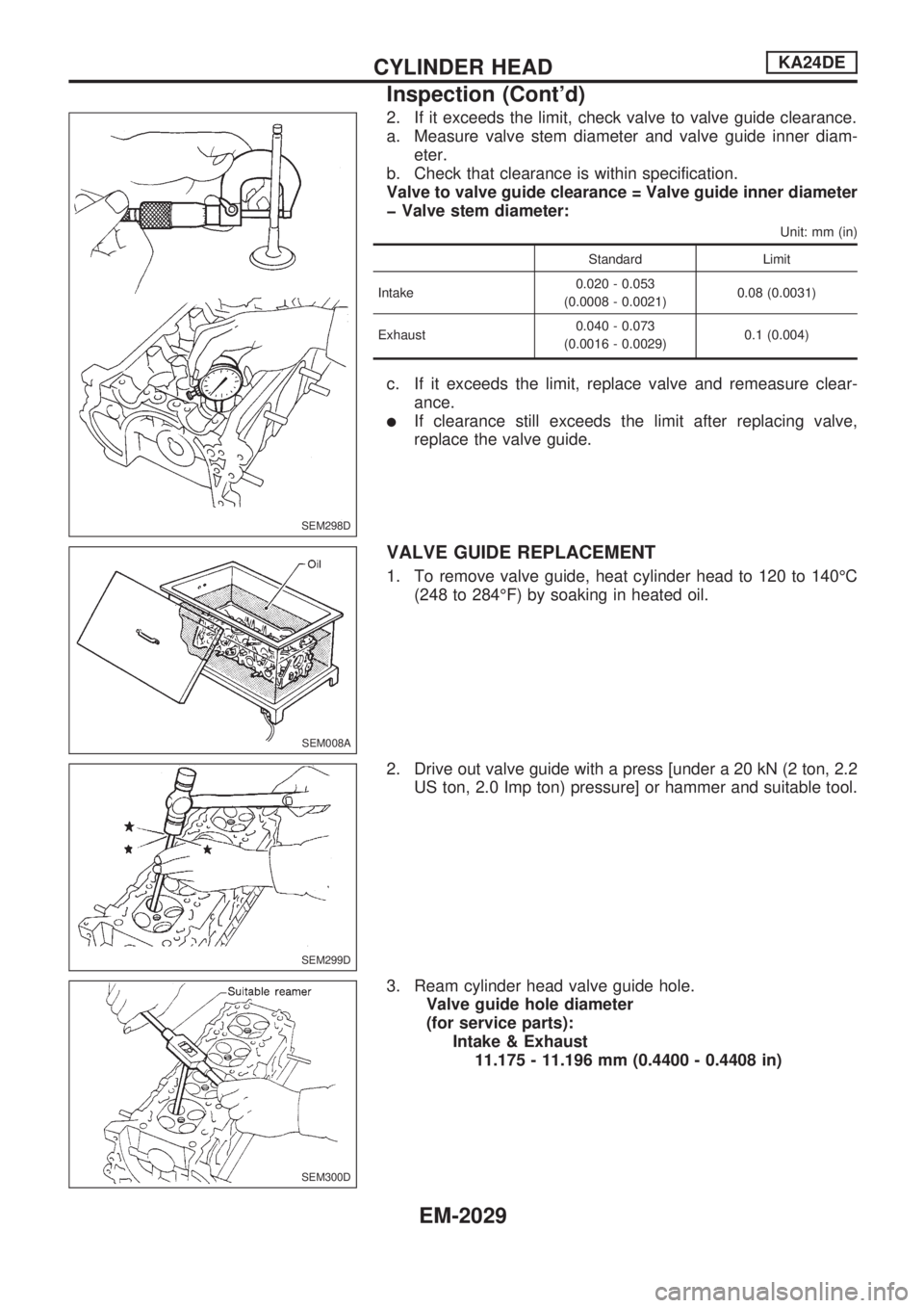
2. If it exceeds the limit, check valve to valve guide clearance.
a. Measure valve stem diameter and valve guide inner diam-
eter.
b. Check that clearance is within specification.
Valve to valve guide clearance = Valve guide inner diameter
þ Valve stem diameter:
Unit: mm (in)
Standard Limit
Intake0.020 - 0.053
(0.0008 - 0.0021)0.08 (0.0031)
Exhaust0.040 - 0.073
(0.0016 - 0.0029)0.1 (0.004)
c. If it exceeds the limit, replace valve and remeasure clear-
ance.
lIf clearance still exceeds the limit after replacing valve,
replace the valve guide.
VALVE GUIDE REPLACEMENT
1. To remove valve guide, heat cylinder head to 120 to 140ÉC
(248 to 284ÉF) by soaking in heated oil.
2. Drive out valve guide with a press [under a 20 kN (2 ton, 2.2
US ton, 2.0 Imp ton) pressure] or hammer and suitable tool.
3. Ream cylinder head valve guide hole.
Valve guide hole diameter
(for service parts):
Intake & Exhaust
11.175 - 11.196 mm (0.4400 - 0.4408 in)
SEM298D
SEM008A
SEM299D
SEM300D
CYLINDER HEADKA24DE
Inspection (Cont'd)
EM-2029
Page 460 of 666
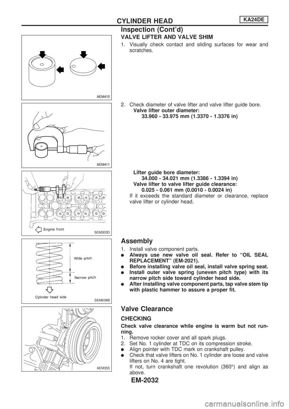
VALVE LIFTER AND VALVE SHIM
1. Visually check contact and sliding surfaces for wear and
scratches.
2. Check diameter of valve lifter and valve lifter guide bore.
Valve lifter outer diameter:
33.960 - 33.975 mm (1.3370 - 1.3376 in)
Lifter guide bore diameter:
34.000 - 34.021 mm (1.3386 - 1.3394 in)
Valve lifter to valve lifter guide clearance:
0.025 - 0.061 mm (0.0010 - 0.0024 in)
If it exceeds the standard diameter or clearance, replace
valve lifter or cylinder head.
Assembly
1. Install valve component parts.
lAlways use new valve oil seal. Refer to ªOIL SEAL
REPLACEMENTº (EM-2021).
lBefore installing valve oil seal, install valve spring seat.
lInstall outer valve spring (uneven pitch type) with its
narrow pitch side toward cylinder head side.
lAfter installing valve component parts, tap valve stem tip
with plastic hammer to assure a proper fit.
Valve Clearance
CHECKING
Check valve clearance while engine is warm but not run-
ning.
1. Remove rocker cover and all spark plugs.
2. Set No. 1 cylinder at TDC on its compression stroke.
lAlign pointer with TDC mark on crankshaft pulley.
lCheck that valve lifters on No. 1 cylinder are loose and valve
lifters on No. 4 are tight.
If not, turn crankshaft one revolution (360É) and align as
above.
AEM410
AEM411
SEM303D
SEM638B
AEM355
CYLINDER HEADKA24DE
Inspection (Cont'd)
EM-2032
Page 468 of 666
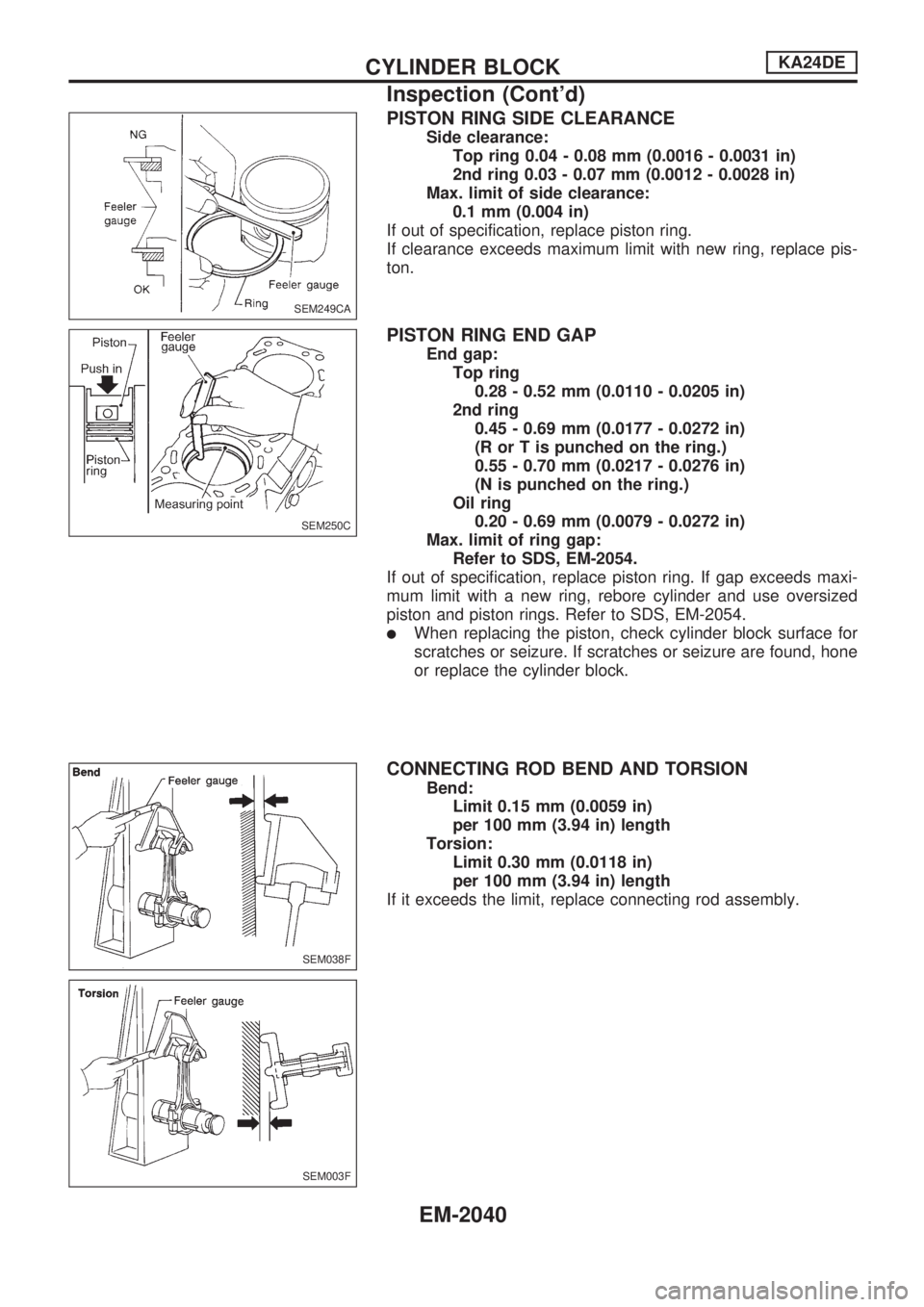
PISTON RING SIDE CLEARANCE
Side clearance:
Top ring 0.04 - 0.08 mm (0.0016 - 0.0031 in)
2nd ring 0.03 - 0.07 mm (0.0012 - 0.0028 in)
Max. limit of side clearance:
0.1 mm (0.004 in)
If out of specification, replace piston ring.
If clearance exceeds maximum limit with new ring, replace pis-
ton.
PISTON RING END GAP
End gap:
Top ring
0.28 - 0.52 mm (0.0110 - 0.0205 in)
2nd ring
0.45 - 0.69 mm (0.0177 - 0.0272 in)
(R or T is punched on the ring.)
0.55 - 0.70 mm (0.0217 - 0.0276 in)
(N is punched on the ring.)
Oil ring
0.20 - 0.69 mm (0.0079 - 0.0272 in)
Max. limit of ring gap:
Refer to SDS, EM-2054.
If out of specification, replace piston ring. If gap exceeds maxi-
mum limit with a new ring, rebore cylinder and use oversized
piston and piston rings. Refer to SDS, EM-2054.
lWhen replacing the piston, check cylinder block surface for
scratches or seizure. If scratches or seizure are found, hone
or replace the cylinder block.
CONNECTING ROD BEND AND TORSION
Bend:
Limit 0.15 mm (0.0059 in)
per 100 mm (3.94 in) length
Torsion:
Limit 0.30 mm (0.0118 in)
per 100 mm (3.94 in) length
If it exceeds the limit, replace connecting rod assembly.
SEM249CA
SEM250C
SEM038F
SEM003F
CYLINDER BLOCKKA24DE
Inspection (Cont'd)
EM-2040
Page 473 of 666
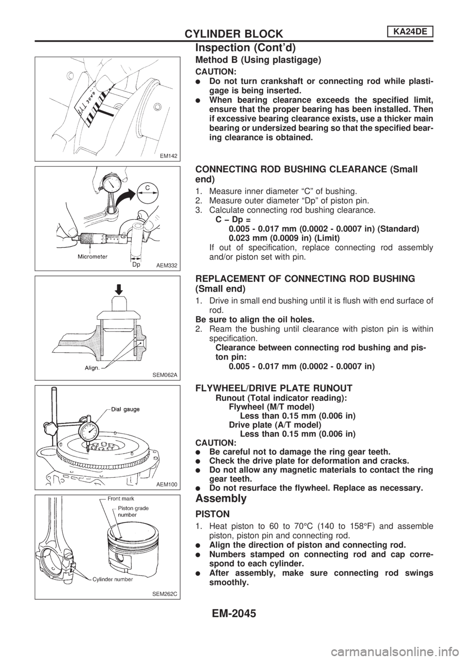
Method B (Using plastigage)
CAUTION:
lDo not turn crankshaft or connecting rod while plasti-
gage is being inserted.
lWhen bearing clearance exceeds the specified limit,
ensure that the proper bearing has been installed. Then
if excessive bearing clearance exists, use a thicker main
bearing or undersized bearing so that the specified bear-
ing clearance is obtained.
CONNECTING ROD BUSHING CLEARANCE (Small
end)
1. Measure inner diameter ªCº of bushing.
2. Measure outer diameter ªDpº of piston pin.
3. Calculate connecting rod bushing clearance.
CþDp=
0.005 - 0.017 mm (0.0002 - 0.0007 in) (Standard)
0.023 mm (0.0009 in) (Limit)
If out of specification, replace connecting rod assembly
and/or piston set with pin.
REPLACEMENT OF CONNECTING ROD BUSHING
(Small end)
1. Drive in small end bushing until it is flush with end surface of
rod.
Be sure to align the oil holes.
2. Ream the bushing until clearance with piston pin is within
specification.
Clearance between connecting rod bushing and pis-
ton pin:
0.005 - 0.017 mm (0.0002 - 0.0007 in)
FLYWHEEL/DRIVE PLATE RUNOUT
Runout (Total indicator reading):
Flywheel (M/T model)
Less than 0.15 mm (0.006 in)
Drive plate (A/T model)
Less than 0.15 mm (0.006 in)
CAUTION:
lBe careful not to damage the ring gear teeth.
lCheck the drive plate for deformation and cracks.
lDo not allow any magnetic materials to contact the ring
gear teeth.
lDo not resurface the flywheel. Replace as necessary.
Assembly
PISTON
1. Heat piston to 60 to 70ÉC (140 to 158ÉF) and assemble
piston, piston pin and connecting rod.
lAlign the direction of piston and connecting rod.
lNumbers stamped on connecting rod and cap corre-
spond to each cylinder.
lAfter assembly, make sure connecting rod swings
smoothly.
EM142
AEM332
SEM062A
AEM100
SEM262C
CYLINDER BLOCKKA24DE
Inspection (Cont'd)
EM-2045
Page 514 of 666
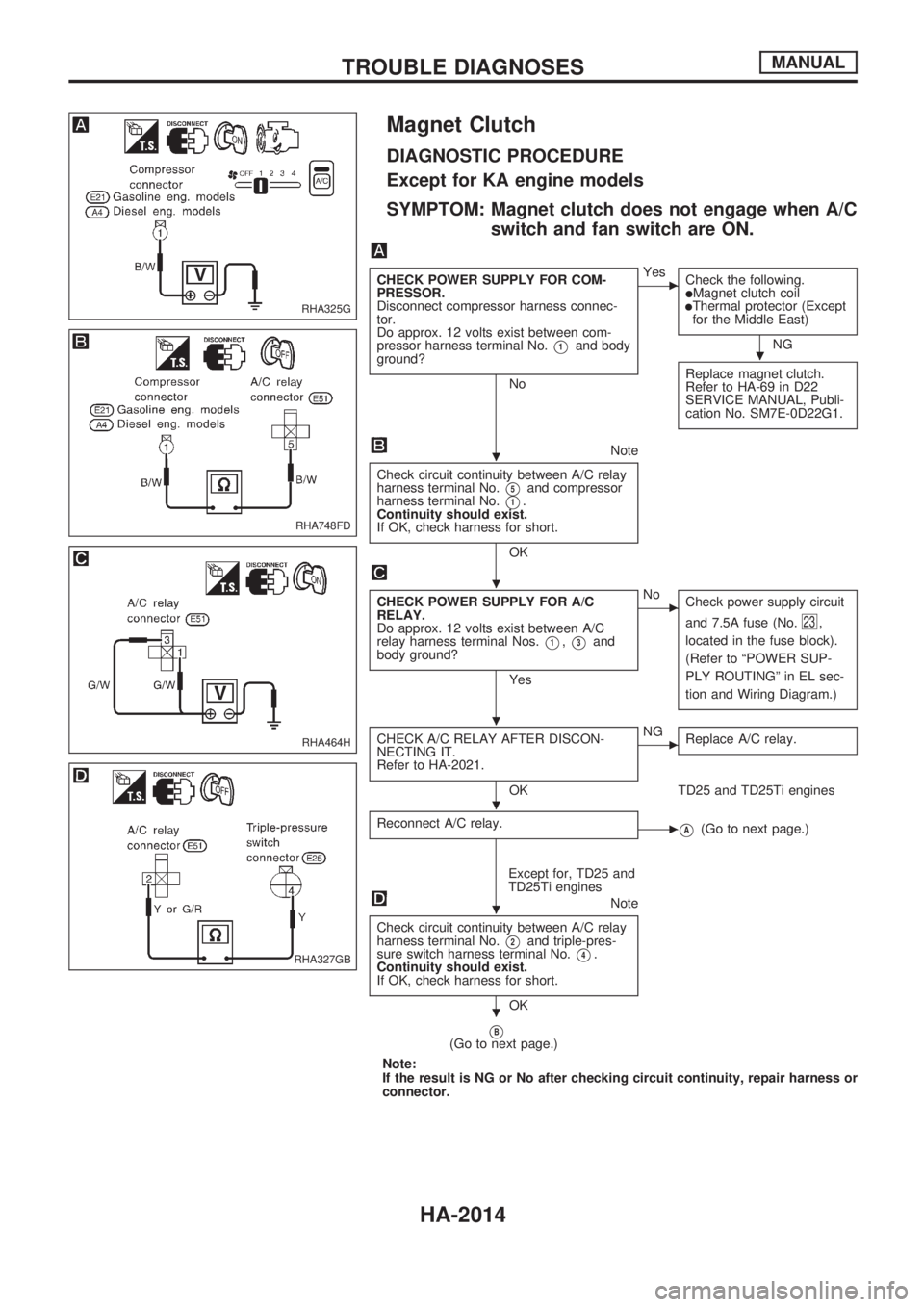
Magnet Clutch
DIAGNOSTIC PROCEDURE
Except for KA engine models
SYMPTOM: Magnet clutch does not engage when A/C
switch and fan switch are ON.
CHECK POWER SUPPLY FOR COM-
PRESSOR.
Disconnect compressor harness connec-
tor.
Do approx. 12 volts exist between com-
pressor harness terminal No.
V1and body
ground?
No
cYes
Check the following.
lMagnet clutch coillThermal protector (Except
for the Middle East)
NG
Replace magnet clutch.
Refer to HA-69 in D22
SERVICE MANUAL, Publi-
cation No. SM7E-0D22G1.
Note
Check circuit continuity between A/C relay
harness terminal No.
V5and compressor
harness terminal No.
V1.
Continuity should exist.
If OK, check harness for short.
OK
CHECK POWER SUPPLY FOR A/C
RELAY.
Do approx. 12 volts exist between A/C
relay harness terminal Nos.
V1,V3and
body ground?
Yes
cNo
Check power supply circuit
and 7.5A fuse (No.
23,
located in the fuse block).
(Refer to ªPOWER SUP-
PLY ROUTINGº in EL sec-
tion and Wiring Diagram.)
CHECK A/C RELAY AFTER DISCON-
NECTING IT.
Refer to HA-2021.
OK
cNG
Replace A/C relay.
TD25 and TD25Ti engines
Reconnect A/C relay.
cVA(Go to next page.)
Except for, TD25 and
TD25Ti engines
Note
Check circuit continuity between A/C relay
harness terminal No.
V2and triple-pres-
sure switch harness terminal No.
V4.
Continuity should exist.
If OK, check harness for short.
OK
VB(Go to next page.)
Note:
If the result is NG or No after checking circuit continuity, repair harness or
connector.
RHA325G
RHA748FD
RHA464H
RHA327GB
.
.
.
.
.
.
.
TROUBLE DIAGNOSESMANUAL
HA-2014