1999 NISSAN PICK-UP ECO mode
[x] Cancel search: ECO modePage 2 of 666
FOREWORD
This manual contains maintenance and repair procedures for NISSAN
PICKUP, model D22 series.
In order to assure your safety and the efficient functioning of the vehicle,
this manual should be read thoroughly. It is especially important that the
PRECAUTIONS in the GI section be completely understood before starting
any repair task.
All information in this manual is based on the latest product information
at the time of publication. The right is reserved to make changes in speci-
®cations and methods at any time without notice.
IMPORTANT SAFETY NOTICE
The proper performance of service is essential for both the safety of the
technician and the efficient functioning of the vehicle.
The service methods in this Service Manual are described in such a man-
ner that the service may be performed safely and accurately.
Service varies with the procedures used, the skills of the technician and the
tools and parts available. Accordingly, anyone using service procedures,
tools or parts which are not speci®cally recommended by NISSAN must
®rst completely satisfy himself that neither his safety nor the vehicle's
safety will be jeopardized by the service method selected.
NISSAN EUROPE S.A.S.
Service Engineering Section
Paris, France
Page 33 of 666
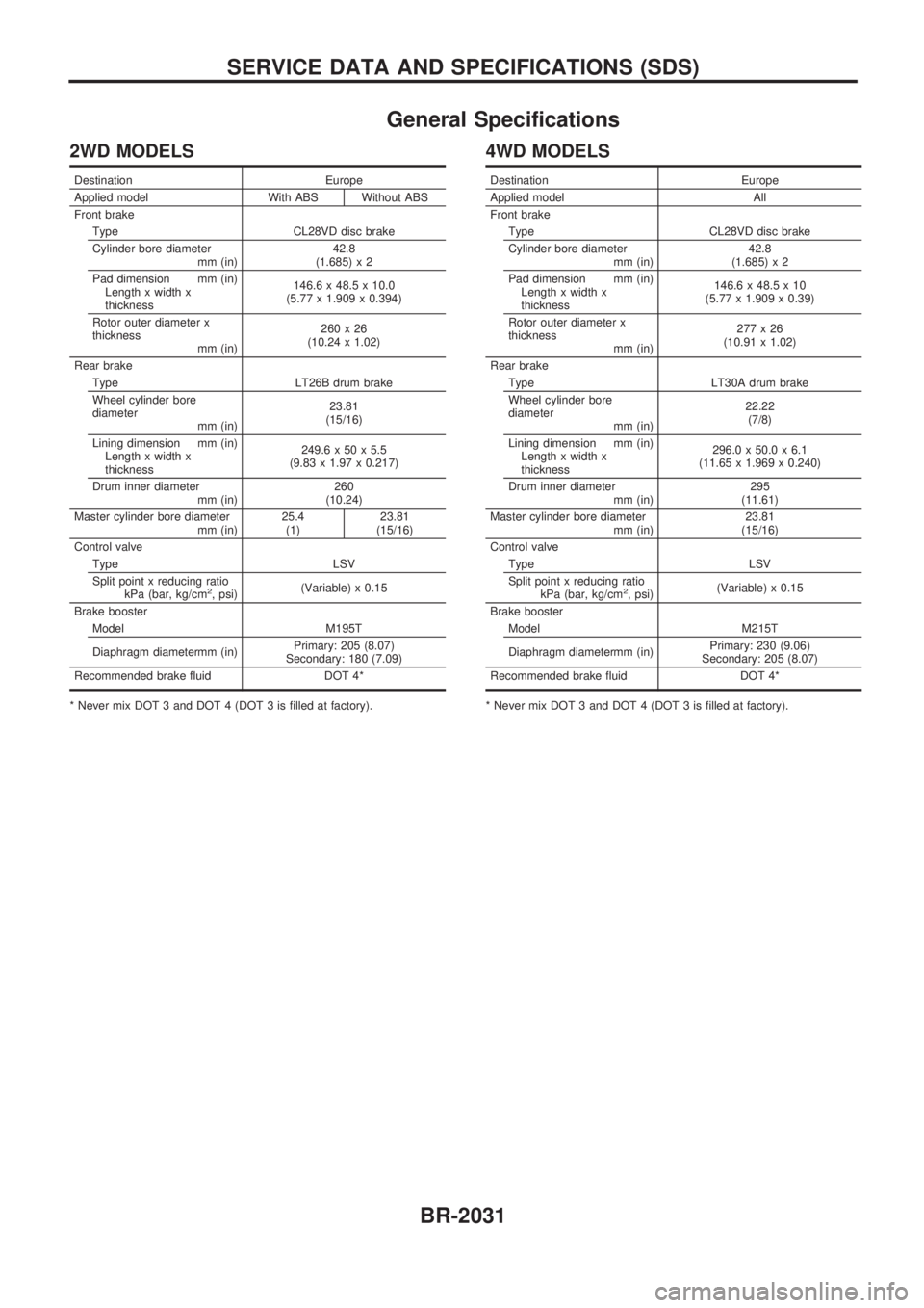
General Specifications
2WD MODELS
Destination Europe
Applied model With ABS Without ABS
Front brake
Type CL28VD disc brake
Cylinder bore diameter
mm (in)42.8
(1.685) x 2
Pad dimension mm (in)
Length x width x
thickness146.6 x 48.5 x 10.0
(5.77 x 1.909 x 0.394)
Rotor outer diameter x
thickness
mm (in)260x26
(10.24 x 1.02)
Rear brake
Type LT26B drum brake
Wheel cylinder bore
diameter
mm (in)23.81
(15/16)
Lining dimension mm (in)
Length x width x
thickness249.6 x 50 x 5.5
(9.83 x 1.97 x 0.217)
Drum inner diameter
mm (in)260
(10.24)
Master cylinder bore diameter
mm (in)25.4
(1)23.81
(15/16)
Control valve
Type LSV
Split point x reducing ratio
kPa (bar, kg/cm
2, psi)(Variable) x 0.15
Brake booster
Model M195T
Diaphragm diametermm (in)Primary: 205 (8.07)
Secondary: 180 (7.09)
Recommended brake fluid DOT 4*
* Never mix DOT 3 and DOT 4 (DOT 3 is filled at factory).
4WD MODELS
Destination Europe
Applied model All
Front brake
Type CL28VD disc brake
Cylinder bore diameter
mm (in)42.8
(1.685) x 2
Pad dimension mm (in)
Length x width x
thickness146.6 x 48.5 x 10
(5.77 x 1.909 x 0.39)
Rotor outer diameter x
thickness
mm (in)277x26
(10.91 x 1.02)
Rear brake
Type LT30A drum brake
Wheel cylinder bore
diameter
mm (in)22.22
(7/8)
Lining dimension mm (in)
Length x width x
thickness296.0 x 50.0 x 6.1
(11.65 x 1.969 x 0.240)
Drum inner diameter
mm (in)295
(11.61)
Master cylinder bore diameter
mm (in)23.81
(15/16)
Control valve
Type LSV
Split point x reducing ratio
kPa (bar, kg/cm
2, psi)(Variable) x 0.15
Brake booster
Model M215T
Diaphragm diametermm (in)Primary: 230 (9.06)
Secondary: 205 (8.07)
Recommended brake fluid DOT 4*
* Never mix DOT 3 and DOT 4 (DOT 3 is filled at factory).
SERVICE DATA AND SPECIFICATIONS (SDS)
BR-2031
Page 46 of 666
ENGINECONTROLSYSTEM
SECTION
EC
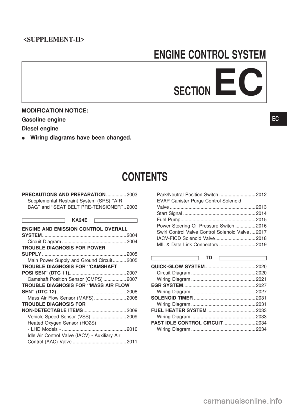
MODIFICATION NOTICE:
Gasoline engine
Diesel engine
lWiring diagrams have been changed.
CONTENTS
PRECAUTIONS AND PREPARATION ............... 2003
Supplemental Restraint System (SRS) ``AIR
BAG'' and ``SEAT BELT PRE-TENSIONER'' .. 2003
KA24E
ENGINE AND EMISSION CONTROL OVERALL
SYSTEM............................................................... 2004
Circuit Diagram ................................................ 2004
TROUBLE DIAGNOSIS FOR POWER
SUPPLY ............................................................... 2005
Main Power Supply and Ground Circuit .......... 2005
TROUBLE DIAGNOSIS FOR ``CAMSHAFT
POSI SEN'' (DTC 11) ........................................... 2007
Camshaft Position Sensor (CMPS) ................. 2007
TROUBLE DIAGNOSIS FOR ``MASS AIR FLOW
SEN'' (DTC 12) .................................................... 2008
Mass Air Flow Sensor (MAFS) ........................ 2008
TROUBLE DIAGNOSIS FOR
NON-DETECTABLE ITEMS ................................ 2009
Vehicle Speed Sensor (VSS) .......................... 2009
Heated Oxygen Sensor (HO2S)
- LHD Models - ................................................ 2010
Idle Air Control Valve (IACV) - Auxiliary Air
Control (AAC) Valve ........................................ 2011 Park/Neutral Position Switch ........................... 2012
EVAP Canister Purge Control Solenoid
Valve ................................................................ 2013
Start Signal ...................................................... 2014
Fuel Pump........................................................ 2015
Power Steering Oil Pressure Switch ............... 2016
Swirl Control Valve Control Solenoid Valve .... 2017
IACV-FICD Solenoid Valve .............................. 2018
MIL & Data Link Connectors ........................... 2019
TD
QUICK-GLOW SYSTEM ...................................... 2020
Circuit Diagram ................................................ 2020
Wiring Diagram ................................................ 2021
EGR SYSTEM ...................................................... 2027
Wiring Diagram ................................................ 2027
SOLENOID TIMER .............................................. 2031
Wiring Diagram ................................................ 2031
FUEL HEATER SYSTEM .................................... 2033
Wiring Diagram ................................................ 2033
FAST IDLE CONTROL CIRCUIT ........................ 2034
Wiring Diagram ................................................ 2034
EC
Page 137 of 666
Unified Control Meter System Description
UNIFIED CONTROL METER
Speedometer, odo/trip meter, tachometer, fuel gauge and water
temperature gauge are controlled totally by unified meter control
unit.
Meter/gauge Operation and Odo/Trip Meter
Segment Check in Diagnosis Mode
DIAGNOSIS FUNCTION
lOdo/trip meter segment can be checked in diagnosis mode.
lMeters/gauges can be checked in diagnosis mode.
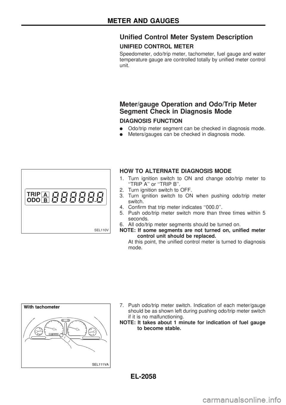
HOW TO ALTERNATE DIAGNOSIS MODE
1. Turn ignition switch to ON and change odo/trip meter to
``TRIP A'' or ``TRIP B''.
2. Turn ignition switch to OFF.
3. Turn ignition switch to ON when pushing odo/trip meter
switch.
4. Confirm that trip meter indicates ``000.0''.
5. Push odo/trip meter switch more than three times within 5
seconds.
6. All odo/trip meter segments should be turned on.
NOTE: If some segments are not turned on, unified meter
control unit should be replaced.
At this point, the unified control meter is turned to diagnosis
mode.
7. Push odo/trip meter switch. Indication of each meter/gauge
should be as shown left during pushing odo/trip meter switch
if it is no malfunctioning.
NOTE: It takes about 1 minute for indication of fuel gauge
to become stable.
SEL110V
SEL111VA
METER AND GAUGES
EL-2058
Page 139 of 666
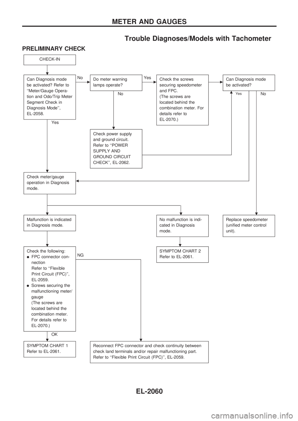
Trouble Diagnoses/Models with Tachometer
PRELIMINARY CHECK
CHECK-IN
Can Diagnosis mode
be activated? Refer to
``Meter/Gauge Opera-
tion and Odo/Trip Meter
Segment Check in
Diagnosis Mode'',
EL-2058.
Yes
cNo
Do meter warning
lamps operate?
No
cYes
Check the screws
securing speedometer
and FPC.
(The screws are
located behind the
combination meter. For
details refer to
EL-2070.)cCan Diagnosis mode
be activated?
NomYes
Check power supply
and ground circuit.
Refer to ``POWER
SUPPLY AND
GROUND CIRCUIT
CHECK'', EL-2062.
Check meter/gauge
operation in Diagnosis
mode.b
Malfunction is indicated
in Diagnosis mode.No malfunction is indi-
cated in Diagnosis
mode.Replace speedometer
(unified meter control
unit).
Check the following:
lFPC connector con-
nection
Refer to ``Flexible
Print Circuit (FPC)'',
EL-2059.
lScrews securing the
malfunctioning meter/
gauge
(The screws are
located behind the
combination meter.
For details refer to
EL-2070.)
OK
NGSYMPTOM CHART 2
Refer to EL-2061.
SYMPTOM CHART 1
Refer to EL-2061.Reconnect FPC connector and check continuity between
check land terminals and/or repair malfunctioning part.
Refer to ``Flexible Print Circuit (FPC)'', EL-2059.
.
.
.
...
..
..
METER AND GAUGES
EL-2060
Page 218 of 666
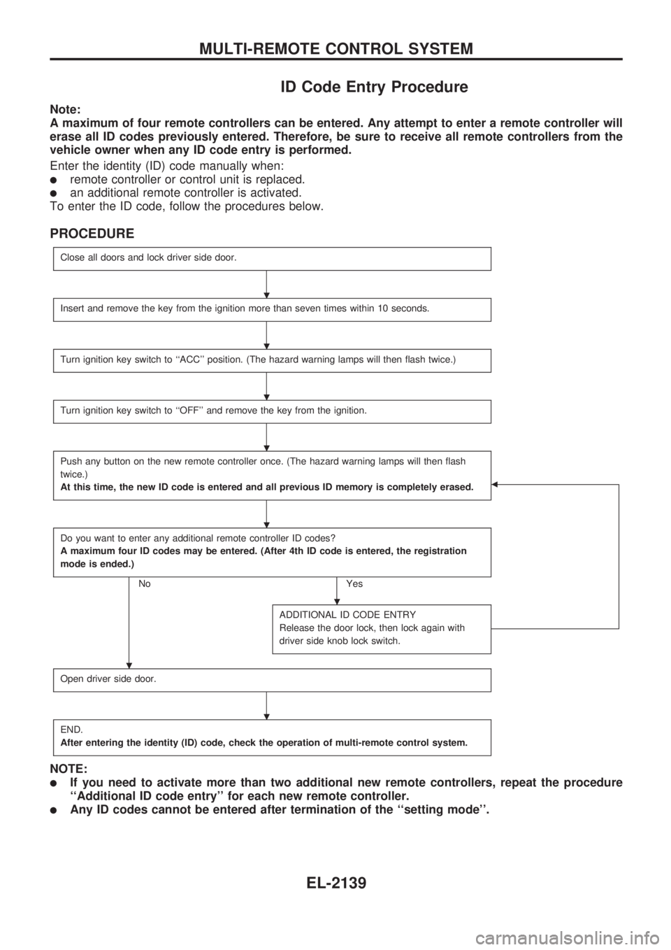
ID Code Entry Procedure
Note:
A maximum of four remote controllers can be entered. Any attempt to enter a remote controller will
erase all ID codes previously entered. Therefore, be sure to receive all remote controllers from the
vehicle owner when any ID code entry is performed.
Enter the identity (ID) code manually when:
lremote controller or control unit is replaced.
lan additional remote controller is activated.
To enter the ID code, follow the procedures below.
PROCEDURE
Close all doors and lock driver side door.
Insert and remove the key from the ignition more than seven times within 10 seconds.
Turn ignition key switch to ``ACC'' position. (The hazard warning lamps will then flash twice.)
Turn ignition key switch to ``OFF'' and remove the key from the ignition.
Push any button on the new remote controller once. (The hazard warning lamps will then flash
twice.)
At this time, the new ID code is entered and all previous ID memory is completely erased.
b
Do you want to enter any additional remote controller ID codes?
A maximum four ID codes may be entered. (After 4th ID code is entered, the registration
mode is ended.)
No Yes
ADDITIONAL ID CODE ENTRY
Release the door lock, then lock again with
driver side knob lock switch.
Open driver side door.
END.
After entering the identity (ID) code, check the operation of multi-remote control system.
NOTE:
lIf you need to activate more than two additional new remote controllers, repeat the procedure
``Additional ID code entry'' for each new remote controller.
lAny ID codes cannot be entered after termination of the ``setting mode''.
.
.
.
.
.
.
.
.
MULTI-REMOTE CONTROL SYSTEM
EL-2139
Page 309 of 666
Unified Control Meter System Description
UNIFIED CONTROL METER
Speedometer, odo/trip meter, tachometer, fuel gauge and water
temperature gauge are controlled totally by unified meter control
unit.
Meter/gauge Operation and Odo/Trip Meter
Segment Check in Diagnosis Mode
DIAGNOSIS FUNCTION
lOdo/trip meter segment can be checked in diagnosis mode.
lMeters/gauges can be checked in diagnosis mode.
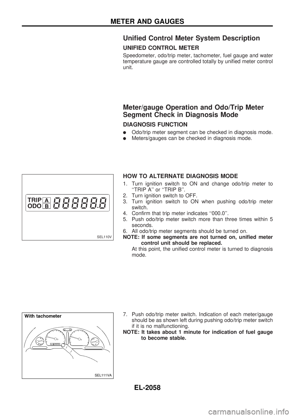
HOW TO ALTERNATE DIAGNOSIS MODE
1. Turn ignition switch to ON and change odo/trip meter to
``TRIP A'' or ``TRIP B''.
2. Turn ignition switch to OFF.
3. Turn ignition switch to ON when pushing odo/trip meter
switch.
4. Confirm that trip meter indicates ``000.0''.
5. Push odo/trip meter switch more than three times within 5
seconds.
6. All odo/trip meter segments should be turned on.
NOTE: If some segments are not turned on, unified meter
control unit should be replaced.
At this point, the unified control meter is turned to diagnosis
mode.
7. Push odo/trip meter switch. Indication of each meter/gauge
should be as shown left during pushing odo/trip meter switch
if it is no malfunctioning.
NOTE: It takes about 1 minute for indication of fuel gauge
to become stable.
SEL110V
SEL111VA
METER AND GAUGES
EL-2058
Page 311 of 666
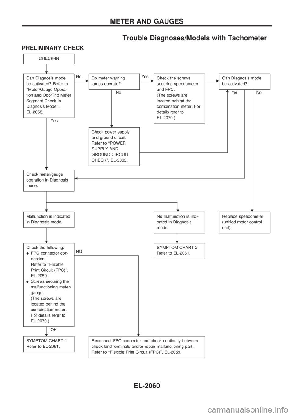
Trouble Diagnoses/Models with Tachometer
PRELIMINARY CHECK
CHECK-IN
Can Diagnosis mode
be activated? Refer to
``Meter/Gauge Opera-
tion and Odo/Trip Meter
Segment Check in
Diagnosis Mode'',
EL-2058.
Yes
cNo
Do meter warning
lamps operate?
No
cYes
Check the screws
securing speedometer
and FPC.
(The screws are
located behind the
combination meter. For
details refer to
EL-2070.)cCan Diagnosis mode
be activated?
NomYes
Check power supply
and ground circuit.
Refer to ``POWER
SUPPLY AND
GROUND CIRCUIT
CHECK'', EL-2062.
Check meter/gauge
operation in Diagnosis
mode.b
Malfunction is indicated
in Diagnosis mode.No malfunction is indi-
cated in Diagnosis
mode.Replace speedometer
(unified meter control
unit).
Check the following:
lFPC connector con-
nection
Refer to ``Flexible
Print Circuit (FPC)'',
EL-2059.
lScrews securing the
malfunctioning meter/
gauge
(The screws are
located behind the
combination meter.
For details refer to
EL-2070.)
OK
NGSYMPTOM CHART 2
Refer to EL-2061.
SYMPTOM CHART 1
Refer to EL-2061.Reconnect FPC connector and check continuity between
check land terminals and/or repair malfunctioning part.
Refer to ``Flexible Print Circuit (FPC)'', EL-2059.
.
.
.
...
..
..
METER AND GAUGES
EL-2060