1999 NISSAN PICK-UP checking oil
[x] Cancel search: checking oilPage 438 of 666
Measurement of Compression Pressure
1. Warm up engine.
2. Turn ignition switch OFF.
3. Release fuel pressure.
Refer to EC section (ªFuel Pressure Releaseº, ªBASIC SER-
VICE PROCEDUREº).
4. Remove all spark plugs.
lClean area around the plug with compressed air before
removing the spark plug.
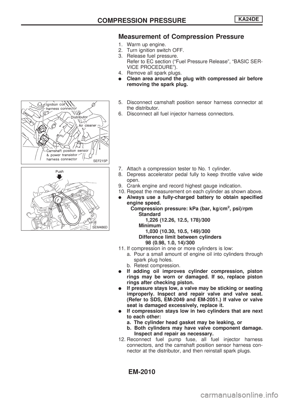
5. Disconnect camshaft position sensor harness connector at
the distributor.
6. Disconnect all fuel injector harness connectors.
7. Attach a compression tester to No. 1 cylinder.
8. Depress accelerator pedal fully to keep throttle valve wide
open.
9. Crank engine and record highest gauge indication.
10. Repeat the measurement on each cylinder as shown above.
lAlways use a fully-charged battery to obtain specified
engine speed.
Compression pressure: kPa (bar, kg/cm
2, psi)/rpm
Standard
1,226 (12.26, 12.5, 178)/300
Minimum
1,030 (10.30, 10.5, 149)/300
Difference limit between cylinders
98 (0.98, 1.0, 14)/300
11. If compression in one or more cylinders is low:
a. Pour a small amount of engine oil into cylinders through
spark plug holes.
b. Retest compression.
lIf adding oil improves cylinder compression, piston
rings may be worn or damaged. If so, replace piston
rings after checking piston.
lIf pressure stays low, a valve may be sticking or seating
improperly. Inspect and repair valve and valve seat.
(Refer to SDS, EM-2049 and EM-2051.) If valve or valve
seat is damaged excessively, replace it.
lIf compression stays low in two cylinders that are next
to each other:
a. The cylinder head gasket may be leaking, or
b. Both cylinders may have valve component damage.
Inspect and repair as necessary.
12. Reconnect fuel pump fuse, all fuel injector harness
connectors, and the camshaft position sensor harness con-
nector at the distributor, and then reinstall spark plugs.
SEF215P
SEM486D
COMPRESSION PRESSUREKA24DE
EM-2010
Page 460 of 666
VALVE LIFTER AND VALVE SHIM
1. Visually check contact and sliding surfaces for wear and
scratches.
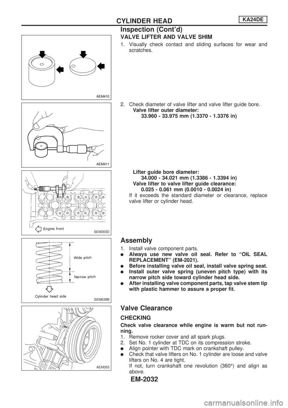
2. Check diameter of valve lifter and valve lifter guide bore.
Valve lifter outer diameter:
33.960 - 33.975 mm (1.3370 - 1.3376 in)
Lifter guide bore diameter:
34.000 - 34.021 mm (1.3386 - 1.3394 in)
Valve lifter to valve lifter guide clearance:
0.025 - 0.061 mm (0.0010 - 0.0024 in)
If it exceeds the standard diameter or clearance, replace
valve lifter or cylinder head.
Assembly
1. Install valve component parts.
lAlways use new valve oil seal. Refer to ªOIL SEAL
REPLACEMENTº (EM-2021).
lBefore installing valve oil seal, install valve spring seat.
lInstall outer valve spring (uneven pitch type) with its
narrow pitch side toward cylinder head side.
lAfter installing valve component parts, tap valve stem tip
with plastic hammer to assure a proper fit.
Valve Clearance
CHECKING
Check valve clearance while engine is warm but not run-
ning.
1. Remove rocker cover and all spark plugs.
2. Set No. 1 cylinder at TDC on its compression stroke.
lAlign pointer with TDC mark on crankshaft pulley.
lCheck that valve lifters on No. 1 cylinder are loose and valve
lifters on No. 4 are tight.
If not, turn crankshaft one revolution (360É) and align as
above.
AEM410
AEM411
SEM303D
SEM638B
AEM355
CYLINDER HEADKA24DE
Inspection (Cont'd)
EM-2032
Page 514 of 666
Magnet Clutch
DIAGNOSTIC PROCEDURE
Except for KA engine models
SYMPTOM: Magnet clutch does not engage when A/C
switch and fan switch are ON.
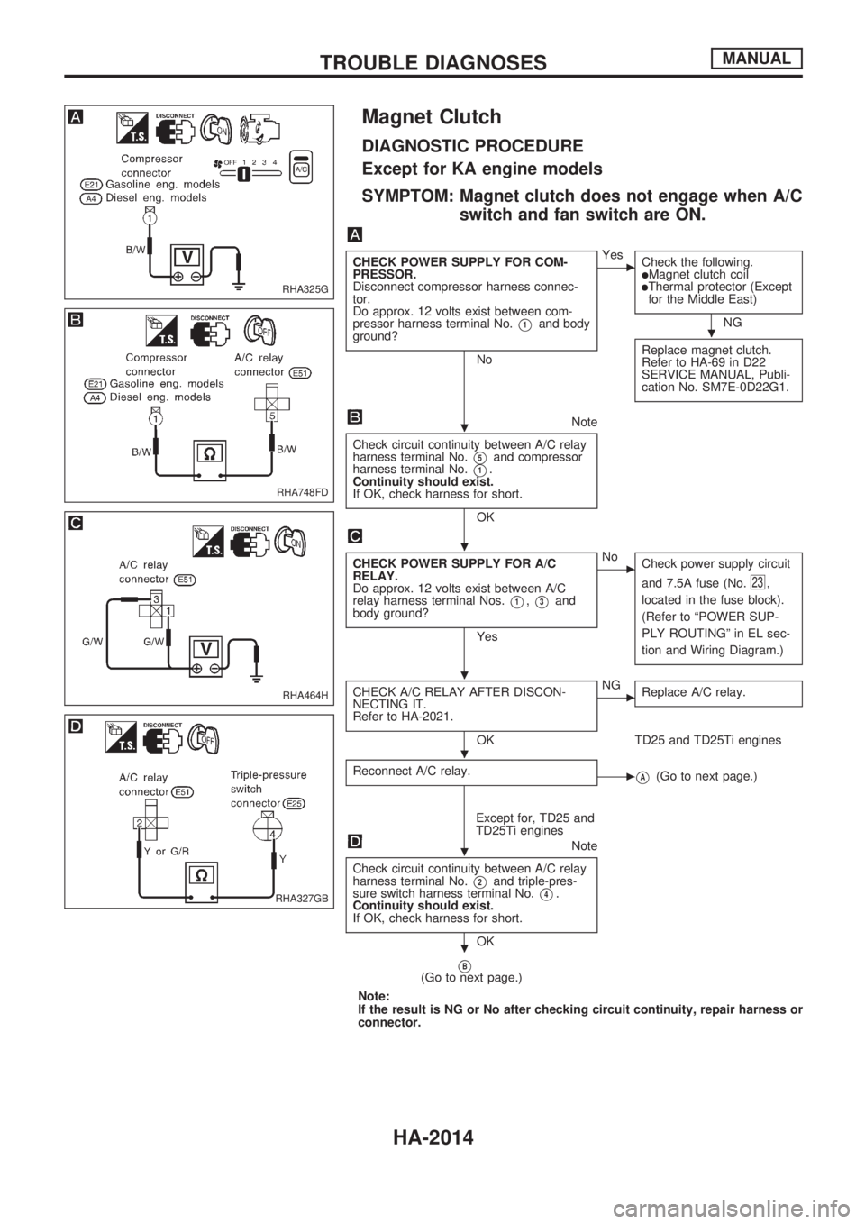
CHECK POWER SUPPLY FOR COM-
PRESSOR.
Disconnect compressor harness connec-
tor.
Do approx. 12 volts exist between com-
pressor harness terminal No.
V1and body
ground?
No
cYes
Check the following.
lMagnet clutch coillThermal protector (Except
for the Middle East)
NG
Replace magnet clutch.
Refer to HA-69 in D22
SERVICE MANUAL, Publi-
cation No. SM7E-0D22G1.
Note
Check circuit continuity between A/C relay
harness terminal No.
V5and compressor
harness terminal No.
V1.
Continuity should exist.
If OK, check harness for short.
OK
CHECK POWER SUPPLY FOR A/C
RELAY.
Do approx. 12 volts exist between A/C
relay harness terminal Nos.
V1,V3and
body ground?
Yes
cNo
Check power supply circuit
and 7.5A fuse (No.
23,
located in the fuse block).
(Refer to ªPOWER SUP-
PLY ROUTINGº in EL sec-
tion and Wiring Diagram.)
CHECK A/C RELAY AFTER DISCON-
NECTING IT.
Refer to HA-2021.
OK
cNG
Replace A/C relay.
TD25 and TD25Ti engines
Reconnect A/C relay.
cVA(Go to next page.)
Except for, TD25 and
TD25Ti engines
Note
Check circuit continuity between A/C relay
harness terminal No.
V2and triple-pres-
sure switch harness terminal No.
V4.
Continuity should exist.
If OK, check harness for short.
OK
VB(Go to next page.)
Note:
If the result is NG or No after checking circuit continuity, repair harness or
connector.
RHA325G
RHA748FD
RHA464H
RHA327GB
.
.
.
.
.
.
.
TROUBLE DIAGNOSESMANUAL
HA-2014
Page 517 of 666
For KA engine models
SYMPTOM: Magnet clutch does not engage when A/C
switch and fan switch are ON.
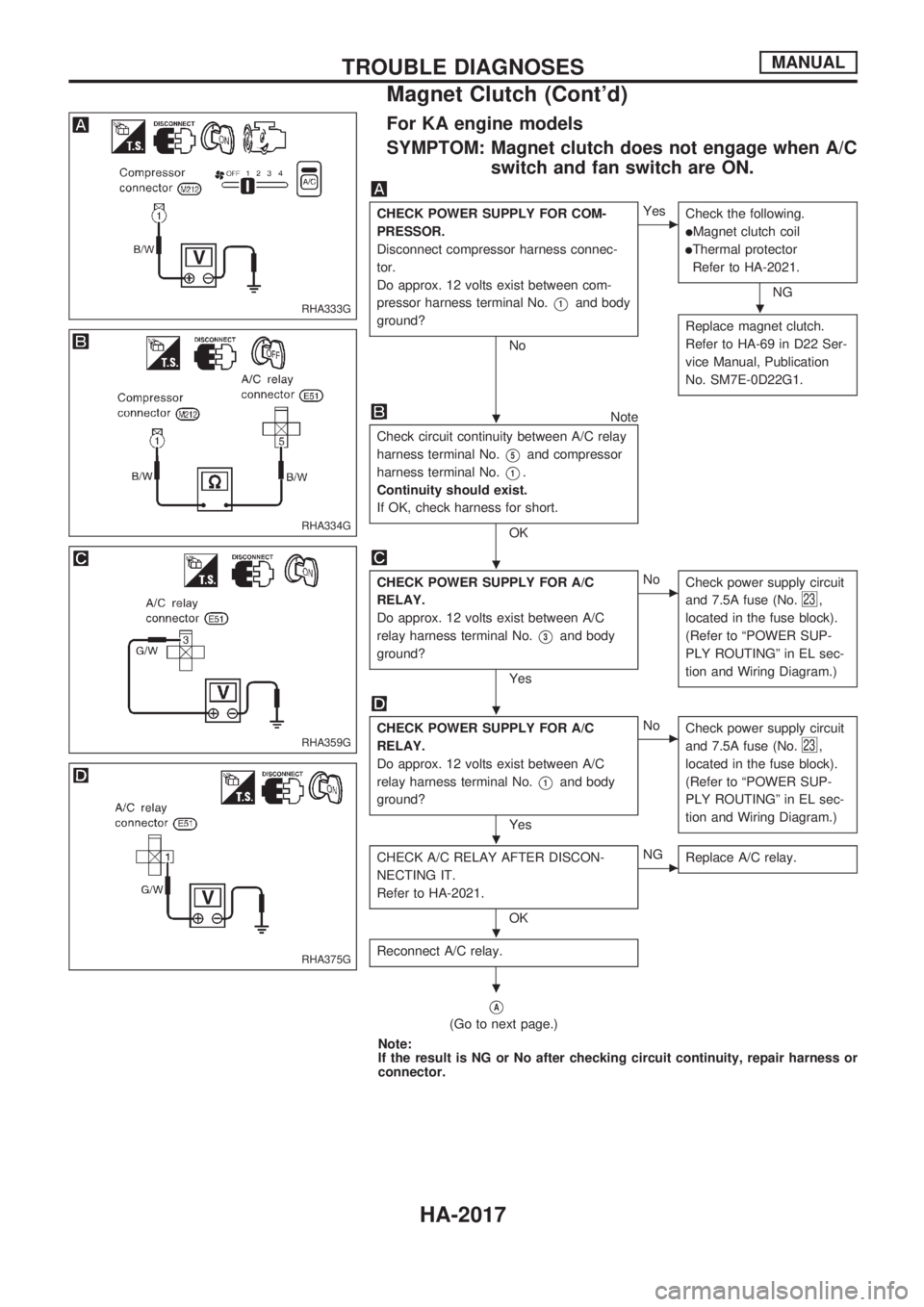
CHECK POWER SUPPLY FOR COM-
PRESSOR.
Disconnect compressor harness connec-
tor.
Do approx. 12 volts exist between com-
pressor harness terminal No.
V1and body
ground?
No
cYes
Check the following.
lMagnet clutch coil
lThermal protector
Refer to HA-2021.
NG
Replace magnet clutch.
Refer to HA-69 in D22 Ser-
vice Manual, Publication
No. SM7E-0D22G1.
Note
Check circuit continuity between A/C relay
harness terminal No.
V5and compressor
harness terminal No.
V1.
Continuity should exist.
If OK, check harness for short.
OK
CHECK POWER SUPPLY FOR A/C
RELAY.
Do approx. 12 volts exist between A/C
relay harness terminal No.
V3and body
ground?
Yes
cNo
Check power supply circuit
and 7.5A fuse (No.
23,
located in the fuse block).
(Refer to ªPOWER SUP-
PLY ROUTINGº in EL sec-
tion and Wiring Diagram.)
CHECK POWER SUPPLY FOR A/C
RELAY.
Do approx. 12 volts exist between A/C
relay harness terminal No.
V1and body
ground?
Yes
cNo
Check power supply circuit
and 7.5A fuse (No.
23,
located in the fuse block).
(Refer to ªPOWER SUP-
PLY ROUTINGº in EL sec-
tion and Wiring Diagram.)
CHECK A/C RELAY AFTER DISCON-
NECTING IT.
Refer to HA-2021.
OK
cNG
Replace A/C relay.
Reconnect A/C relay.
VA
(Go to next page.)
Note:
If the result is NG or No after checking circuit continuity, repair harness or
connector.
RHA333G
RHA334G
RHA359G
RHA375G
.
.
.
.
.
.
.
TROUBLE DIAGNOSESMANUAL
Magnet Clutch (Cont'd)
HA-2017
Page 518 of 666
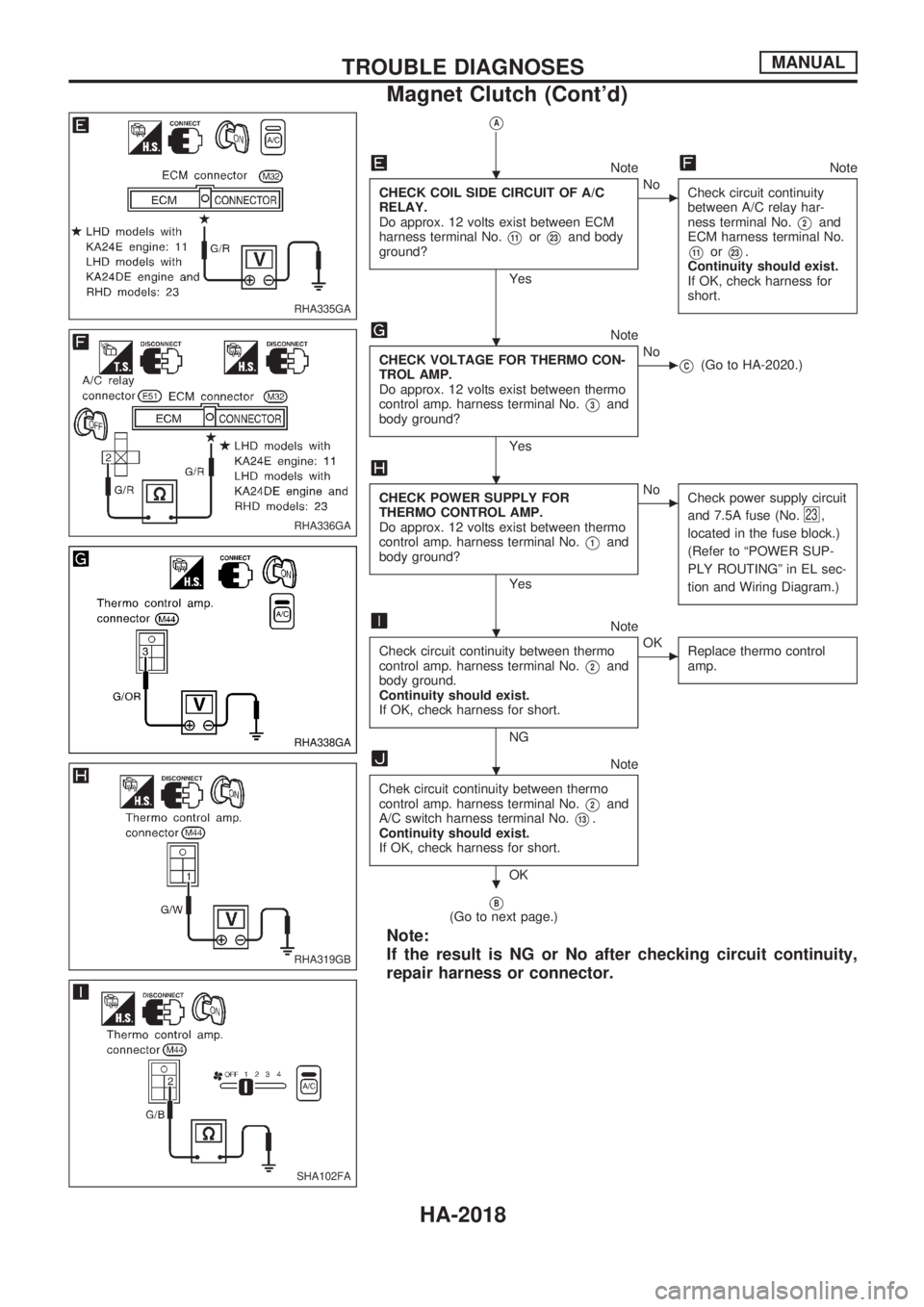
VA
NoteNote
CHECK COIL SIDE CIRCUIT OF A/C
RELAY.
Do approx. 12 volts exist between ECM
harness terminal No.
V11orV23and body
ground?
Yes
cNo
Check circuit continuity
between A/C relay har-
ness terminal No.
V2and
ECM harness terminal No.
V11orV23.
Continuity should exist.
If OK, check harness for
short.
Note
CHECK VOLTAGE FOR THERMO CON-
TROL AMP.
Do approx. 12 volts exist between thermo
control amp. harness terminal No.
V3and
body ground?
Yes
cNo
VC(Go to HA-2020.)
CHECK POWER SUPPLY FOR
THERMO CONTROL AMP.
Do approx. 12 volts exist between thermo
control amp. harness terminal No.
V1and
body ground?
Yes
cNo
Check power supply circuit
and 7.5A fuse (No.
23,
located in the fuse block.)
(Refer to ªPOWER SUP-
PLY ROUTINGº in EL sec-
tion and Wiring Diagram.)
Note
Check circuit continuity between thermo
control amp. harness terminal No.
V2and
body ground.
Continuity should exist.
If OK, check harness for short.
NG
cOK
Replace thermo control
amp.
Note
Chek circuit continuity between thermo
control amp. harness terminal No.
V2and
A/C switch harness terminal No.
V13.
Continuity should exist.
If OK, check harness for short.
OK
VB(Go to next page.)
Note:
If the result is NG or No after checking circuit continuity,
repair harness or connector.
RHA335GA
RHA336GA
RHA338GA
RHA319GB
SHA102FA
.
.
.
.
.
.
TROUBLE DIAGNOSESMANUAL
Magnet Clutch (Cont'd)
HA-2018
Page 570 of 666
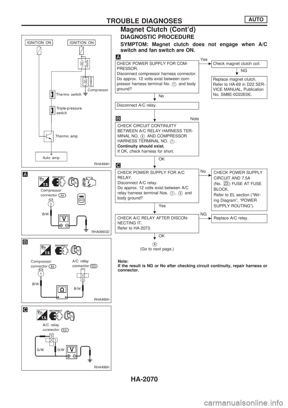
DIAGNOSTIC PROCEDURE
SYMPTOM: Magnet clutch does not engage when A/C
switch and fan switch are ON.
CHECK POWER SUPPLY FOR COM-
PRESSOR.
Disconnect compressor harness connector.
Do approx. 12 volts exist between com-
pressor harness terminal No.
V1and body
ground?
No
cYes
Check magnet clutch coil.
NG
Replace magnet clutch.
Refer to HA-69 in D22 SER-
VICE MANUAL, Publication
No. SM8E-0D22E0E.
Disconnect A/C relay.
Note
CHECK CIRCUIT CONTINUITY
BETWEEN A/C RELAY HARNESS TER-
MINAL NO.
V5AND COMPRESSOR
HARNESS TERMINAL NO.
V1.
Continuity should exist.
If OK, check harness for short.
OK
CHECK POWER SUPPLY FOR A/C
RELAY.
Disconnect A/C relay.
Do approx. 12 volts exist between A/C
relay harness terminal Nos.
V1,V3and
body ground?
Yes
cNo
CHECK POWER SUPPLY
CIRCUIT AND 7.5A
(No.
23) FUSE AT FUSE
BLOCK.
Refer to EL section (ªWir-
ing Diagramº, ªPOWER
SUPPLY ROUTINGº).
CHECK A/C RELAY AFTER DISCON-
NECTING IT.
Refer to HA-2073.
OK
cNG
Replace A/C relay.
VA
(Go to next page.)
Note:
If the result is NG or No after checking circuit continuity, repair harness or
connector.
RHA494H
RHA096GD
RHA495H
RHA496H
.
.
.
.
.
.
TROUBLE DIAGNOSESAUTO
Magnet Clutch (Cont'd)
HA-2070