Page 95 of 666
Service Data and Specifications (SDS)
ALTERNATOR
TypeLR170-765 LR160-728F
HITACHI
Applied model KA24 TD25
Nominal rating V-A 12-70 12-60
Ground polarityNegative
Minimum revolution under no-
load
(When 13.5V is applied) rpmLess than 1,000
Hot output current
(When 13.5V is applied) A/rpmMore than
17/1,300
More than
54/2,500
More than
75/5,000More than
17/1,300
More than
48/2,500
More than
57/5,000
Regulated output voltage V 14.1 - 14.7
Minimum length of brush
mm (in)6.0 (0.236)
Brush spring pressure
N (g, oz)1.0 - 3.43 (102 - 350, 3.60 - 12.34)
Slip ring minimum outer diameter
mm (in)26.0 (1.024)
Rotor (Field coil) resistanceW2.58
*: Models with power steering and air conditioner
CHARGING SYSTEM
EL-2016
Page 267 of 666
Service Data and Specifications (SDS)
ALTERNATOR
TypeLR170-765 LR160-728F
HITACHI
Applied model KA24 TD25
Nominal rating V-A 12-70 12-60
Ground polarityNegative
Minimum revolution under no-
load
(When 13.5V is applied) rpmLess than 1,000
Hot output current
(When 13.5V is applied) A/rpmMore than
17/1,300
More than
54/2,500
More than
75/5,000More than
17/1,300
More than
48/2,500
More than
57/5,000
Regulated output voltage V 14.1 - 14.7
Minimum length of brush
mm (in)6.0 (0.236)
Brush spring pressure
N (g, oz)1.0 - 3.43 (102 - 350, 3.60 - 12.34)
Slip ring minimum outer diameter
mm (in)26.0 (1.024)
Rotor (Field coil) resistanceW2.58
*: Models with power steering and air conditioner
CHARGING SYSTEM
EL-2016
Page 460 of 666

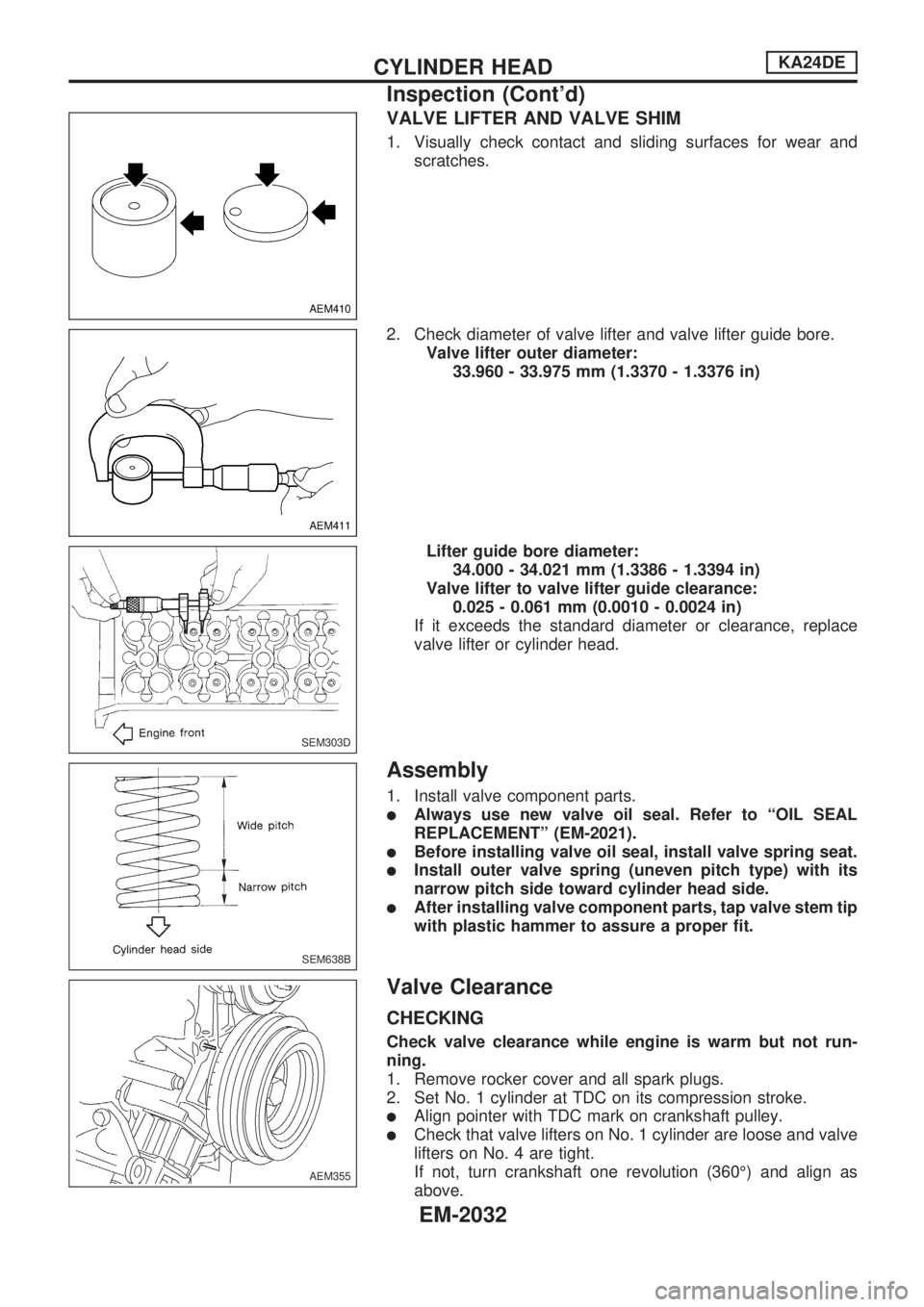
VALVE LIFTER AND VALVE SHIM
1. Visually check contact and sliding surfaces for wear and
scratches.
2. Check diameter of valve lifter and valve lifter guide bore.
Valve lifter outer diameter:
33.960 - 33.975 mm (1.3370 - 1.3376 in)
Lifter guide bore diameter:
34.000 - 34.021 mm (1.3386 - 1.3394 in)
Valve lifter to valve lifter guide clearance:
0.025 - 0.061 mm (0.0010 - 0.0024 in)
If it exceeds the standard diameter or clearance, replace
valve lifter or cylinder head.
Assembly
1. Install valve component parts.
lAlways use new valve oil seal. Refer to ªOIL SEAL
REPLACEMENTº (EM-2021).
lBefore installing valve oil seal, install valve spring seat.
lInstall outer valve spring (uneven pitch type) with its
narrow pitch side toward cylinder head side.
lAfter installing valve component parts, tap valve stem tip
with plastic hammer to assure a proper fit.
Valve Clearance
CHECKING
Check valve clearance while engine is warm but not run-
ning.
1. Remove rocker cover and all spark plugs.
2. Set No. 1 cylinder at TDC on its compression stroke.
lAlign pointer with TDC mark on crankshaft pulley.
lCheck that valve lifters on No. 1 cylinder are loose and valve
lifters on No. 4 are tight.
If not, turn crankshaft one revolution (360É) and align as
above.
AEM410
AEM411
SEM303D
SEM638B
AEM355
CYLINDER HEADKA24DE
Inspection (Cont'd)
EM-2032
Page 598 of 666

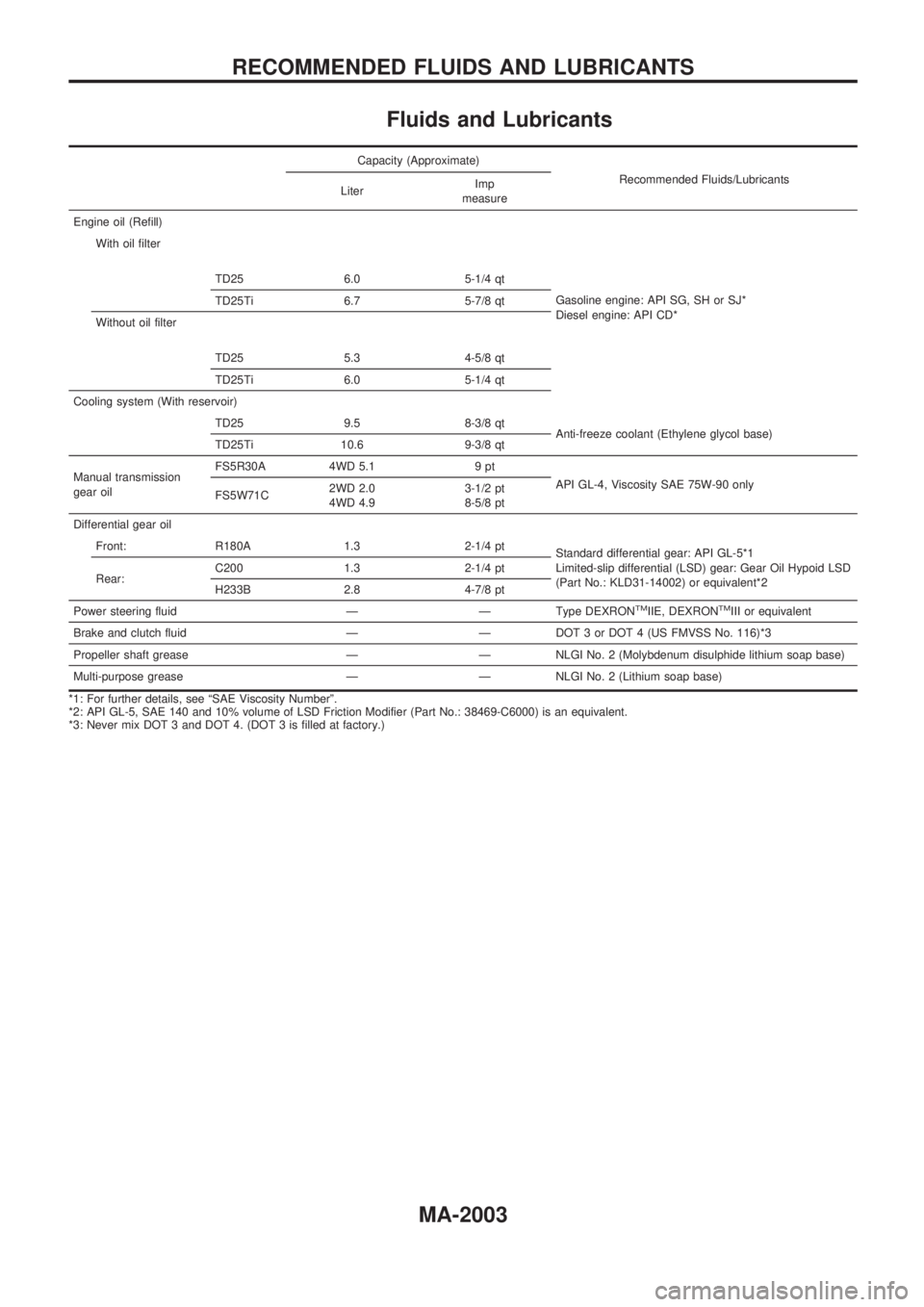
Fluids and Lubricants
Capacity (Approximate)
Recommended Fluids/Lubricants
LiterImp
measure
Engine oil (Refill)
With oil filter
TD25 6.0 5-1/4 qt
Gasoline engine: API SG, SH or SJ*
Diesel engine: API CD* TD25Ti 6.7 5-7/8 qt
Without oil filter
TD25 5.3 4-5/8 qt
TD25Ti 6.0 5-1/4 qt
Cooling system (With reservoir)
TD25 9.5 8-3/8 qt
Anti-freeze coolant (Ethylene glycol base)
TD25Ti 10.6 9-3/8 qt
Manual transmission
gear oilFS5R30A 4WD 5.1 9 pt
API GL-4, Viscosity SAE 75W-90 only
FS5W71C2WD 2.0
4WD 4.93-1/2 pt
8-5/8 pt
Differential gear oil
Front: R180A 1.3 2-1/4 pt
Standard differential gear: API GL-5*1
Limited-slip differential (LSD) gear: Gear Oil Hypoid LSD
(Part No.: KLD31-14002) or equivalent*2 Rear:C200 1.3 2-1/4 pt
H233B 2.8 4-7/8 pt
Power steering fluid Ð Ð Type DEXRON
TMIIE, DEXRONTMIII or equivalent
Brake and clutch fluid Ð Ð DOT 3 or DOT 4 (US FMVSS No. 116)*3
Propeller shaft grease Ð Ð NLGI No. 2 (Molybdenum disulphide lithium soap base)
Multi-purpose grease Ð Ð NLGI No. 2 (Lithium soap base)
*1: For further details, see ªSAE Viscosity Numberº.
*2: API GL-5, SAE 140 and 10% volume of LSD Friction Modifier (Part No.: 38469-C6000) is an equivalent.
*3: Never mix DOT 3 and DOT 4. (DOT 3 is filled at factory.)
RECOMMENDED FLUIDS AND LUBRICANTS
MA-2003
Page 606 of 666
General Specifications
Applied model2WD 4WD
KA24E TD25 KA24E TD25T
Transmission FS5W71C FS5R30A
Number of speed 5
Shift pattern
Synchromesh type Warner
Gear ratio
1st 3.592 3.985 3.592 3.580
2nd 2.246 2.246 2.246 2.077
3rd 1.415 1.415 1.415 1.360
4th 1.000 1.000 1.000 1.000
OD 0.821 0.821 0.821 0.811
Reverse 3.657 3.657 3.657 3.636
Number of teeth
Mainshaft
Drive 21 21 21 22
1st 33 34 33 32
2nd 28 28 28 30
3rd 26 26 26 29
OD 21 21 21 24
Reverse 36 36 36 30
Countershaft
Drive 32 32 32 32
1st 14 13 14 13
2nd 19 19 19 21
3rd 28 28 28 31
OD 39 39 39 43
Reverse 15 15 15 12
Reverse idler gear 21 22
Oil capacity
!(lmp pt)2.0 (3-1/2) 4.9 (8-5/8) 5.1 (9)
RemarksSub-gearCounter
drive gearInstalled
2nd & 3rd double baulk
ring type synchronizer Reverse
idler gearNot installed
Double baulk
ring type
synchronizer2nd and 3rd gears
Reverse
synchronizerInstalled
SERVICE DATA AND
SPECIFICATIONS (SDS)FS5W71C & FS5R30A
MT-2007
Page 620 of 666
![NISSAN PICK-UP 1999 Repair Manual GENERAL SPECIFICATIONS
INSPECTION AND ADJUSTMENT (C200)
Drive pinion preload adjustment
Drive pinion bearing preload
adjusting methodCollapsible spacer
Drive pinion preload [P
1]
N´m (kg-cm, in-lb)
W NISSAN PICK-UP 1999 Repair Manual GENERAL SPECIFICATIONS
INSPECTION AND ADJUSTMENT (C200)
Drive pinion preload adjustment
Drive pinion bearing preload
adjusting methodCollapsible spacer
Drive pinion preload [P
1]
N´m (kg-cm, in-lb)
W](/manual-img/5/57373/w960_57373-619.png)
GENERAL SPECIFICATIONS
INSPECTION AND ADJUSTMENT (C200)
Drive pinion preload adjustment
Drive pinion bearing preload
adjusting methodCollapsible spacer
Drive pinion preload [P
1]
N´m (kg-cm, in-lb)
With front oil seal 1.1 - 1.4 (11 - 14, 9.5 - 12.2)
Without front oil seal 1.0 - 1.3 (10 - 13, 8.7 - 11.3)
Total preload adjustment
Total preload
N´m (kg-cm, in-lb)P1* + [0.3 to 1.5
(3 to 15, 2.6 to 13.0)]
Ring gear backlash mm (in)0.13 - 0.18
(0.0051 - 0.0071)
*: P1: Drive pinion preload
Ð Additional service for LSD model Ð
Differential torque adjustment
Differential torque
N´m (kg-m, ft-lb)88 - 108
(9.0 - 11.0, 65 - 80)
Number of discs and plates
Friction disc
Friction plate
Spring plate12
12
2
Wear limit of plate and disc
mm (in)0.1 (0.004)
Allowable warpage of friction disc
and plate mm (in)0.08 (0.0031)
Total thickness mm (in) 18.24 - 20.36 (0.7181 - 0.8016)
Available discs and plates
Part name Thickness mm (in) Part number
Friction disc1.5 (0.059)38433-C6002
(Standard type)
1.6 (0.063)38433-C6003
(Adjusting type)
Friction plate 1.5 (0.059) 38432-C6001
Spring plate 1.5 (0.059) 38435-C6011
INSPECTION AND ADJUSTMENT (H233B)
Drive pinion preload adjustment
Drive pinion bearing preload adjust-
ing methodAdjusting shim and spacer
Drive pinion preload [P
2]
N´m (kg-cm, in-lb)
With front oil seal1.4 - 2.2
(14 - 22, 12 - 19)
Without front oil seal1.2 - 2.0
(12 - 20, 10 - 17)
Available drive pinion preload adjusting shims
Thickness mm (in) Part number
2.31 (0.0909)
2.33 (0.0917)
2.35 (0.0925)
2.37 (0.0933)
2.39 (0.0941)
2.41 (0.0949)
2.43 (0.0957)
2.45 (0.0965)
2.47 (0.0972)
2.49 (0.0980)
2.51 (0.0988)
2.53 (0.0996)
2.55 (0.1004)
2.57 (0.1012)
2.59 (0.1020)38125-82100
38126-82100
38127-82100
38128-82100
38129-82100
38130-82100
38131-82100
38132-82100
38133-82100
38134-82100
38135-82100
38136-82100
38137-82100
38138-82100
38139-82100
Available drive pinion preload adjusting spacers
Length mm (in) Part number
4.50 (0.1772)
4.75 (0.1870)
5.00 (0.1969)
5.25 (0.2067)
5.50 (0.2165)38165-76000
38166-76000
38167-76000
38166-01J00
38166-01J10
Total preload adjustment
Total preload with front oil seal
N´m (kg-cm, in-lb)P2* + [0.3 to 0.4
(3 to 4, 2.6 to 3.5)]
Ring gear backlash
mm (in)Gear ratio
4.6360.10 - 0.15
(0.0039 - 0.0059)
4.875
5.1430.13 - 0.18
(0.0051 - 0.0071)
*: P2: Drive pinion preload
SERVICE DATA AND SPECIFICATIONS (SDS)
Propeller Shaft (Cont'd)
PD-2014