1999 NISSAN PICK-UP sensor
[x] Cancel search: sensorPage 215 of 666
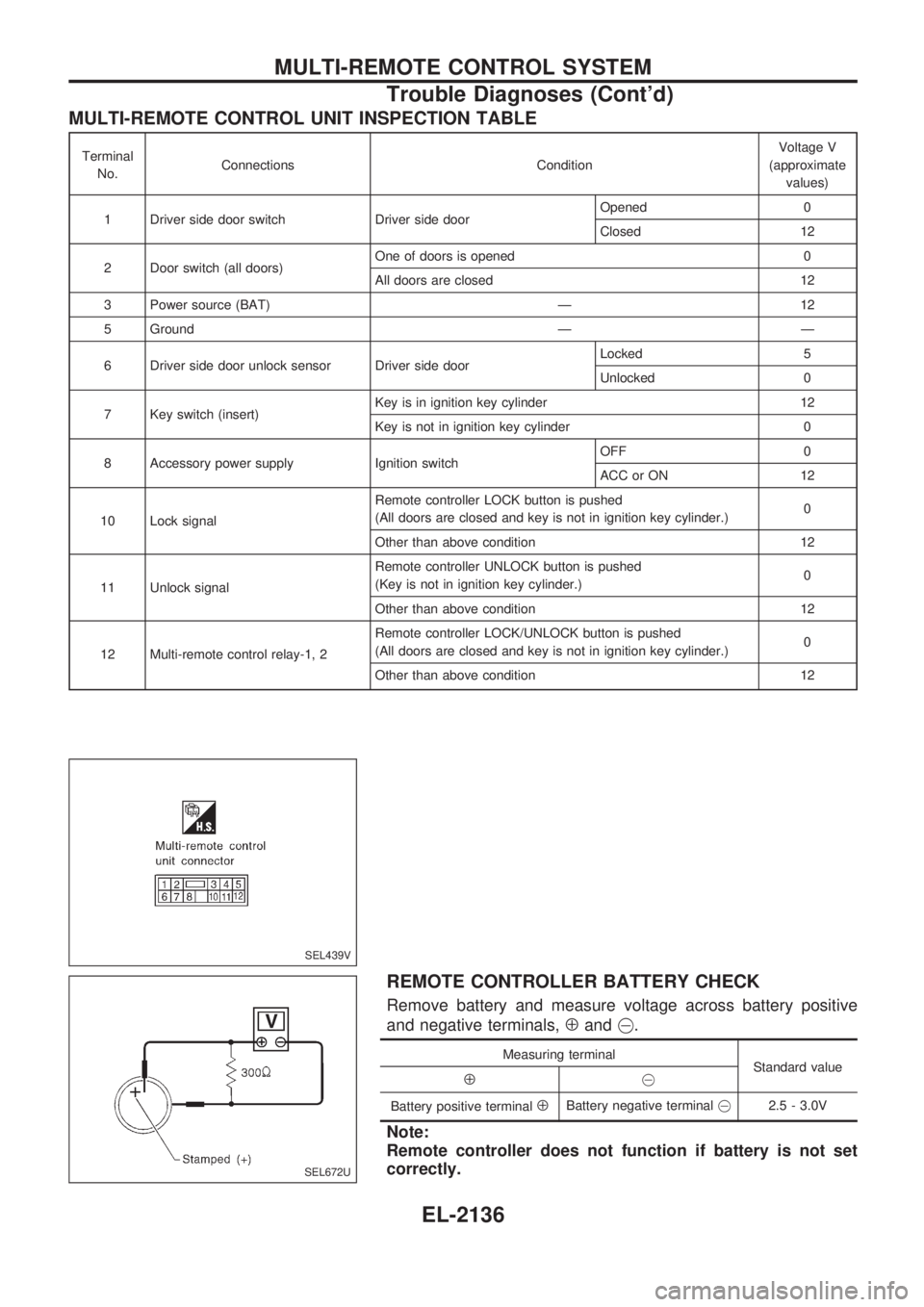
MULTI-REMOTE CONTROL UNIT INSPECTION TABLE
Terminal
No.Connections ConditionVoltage V
(approximate
values)
1 Driver side door switch Driver side doorOpened 0
Closed 12
2 Door switch (all doors)One of doors is opened 0
All doors are closed 12
3 Power source (BAT) Ð 12
5 Ground Ð Ð
6 Driver side door unlock sensor Driver side doorLocked 5
Unlocked 0
7 Key switch (insert)Key is in ignition key cylinder 12
Key is not in ignition key cylinder 0
8 Accessory power supply Ignition switchOFF 0
ACC or ON 12
10 Lock signalRemote controller LOCK button is pushed
(All doors are closed and key is not in ignition key cylinder.)0
Other than above condition 12
11 Unlock signalRemote controller UNLOCK button is pushed
(Key is not in ignition key cylinder.)0
Other than above condition 12
12 Multi-remote control relay-1, 2Remote controller LOCK/UNLOCK button is pushed
(All doors are closed and key is not in ignition key cylinder.)0
Other than above condition 12
REMOTE CONTROLLER BATTERY CHECK
Remove battery and measure voltage across battery positive
and negative terminals,
Åand@.
Measuring terminal
Standard value
Å@
Battery positive terminal
ÅBattery negative [email protected] - 3.0V
Note:
Remote controller does not function if battery is not set
correctly.
SEL439V
SEL672U
MULTI-REMOTE CONTROL SYSTEM
Trouble Diagnoses (Cont'd)
EL-2136
Page 250 of 666
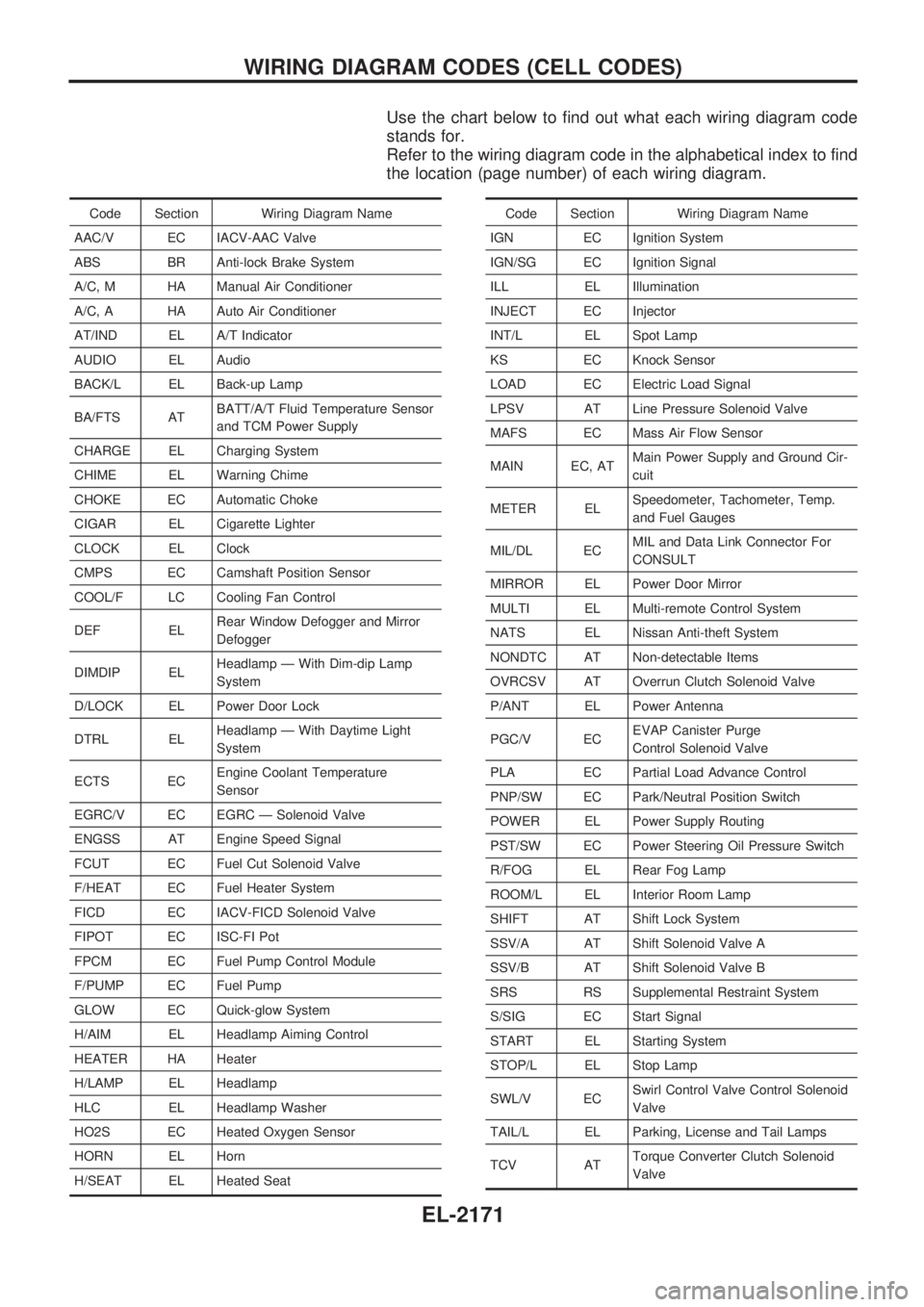
Use the chart below to find out what each wiring diagram code
stands for.
Refer to the wiring diagram code in the alphabetical index to find
the location (page number) of each wiring diagram.
Code Section Wiring Diagram Name
AAC/V EC IACV-AAC Valve
ABS BR Anti-lock Brake System
A/C, M HA Manual Air Conditioner
A/C, A HA Auto Air Conditioner
AT/IND EL A/T Indicator
AUDIO EL Audio
BACK/L EL Back-up Lamp
BA/FTS ATBATT/A/T Fluid Temperature Sensor
and TCM Power Supply
CHARGE EL Charging System
CHIME EL Warning Chime
CHOKE EC Automatic Choke
CIGAR EL Cigarette Lighter
CLOCK EL Clock
CMPS EC Camshaft Position Sensor
COOL/F LC Cooling Fan Control
DEF ELRear Window Defogger and Mirror
Defogger
DIMDIP ELHeadlamp Ð With Dim-dip Lamp
System
D/LOCK EL Power Door Lock
DTRL ELHeadlamp Ð With Daytime Light
System
ECTS ECEngine Coolant Temperature
Sensor
EGRC/V EC EGRC Ð Solenoid Valve
ENGSS AT Engine Speed Signal
FCUT EC Fuel Cut Solenoid Valve
F/HEAT EC Fuel Heater System
FICD EC IACV-FICD Solenoid Valve
FIPOT EC ISC-FI Pot
FPCM EC Fuel Pump Control Module
F/PUMP EC Fuel Pump
GLOW EC Quick-glow System
H/AIM EL Headlamp Aiming Control
HEATER HA Heater
H/LAMP EL Headlamp
HLC EL Headlamp Washer
HO2S EC Heated Oxygen Sensor
HORN EL Horn
H/SEAT EL Heated SeatCode Section Wiring Diagram Name
IGN EC Ignition System
IGN/SG EC Ignition Signal
ILL EL Illumination
INJECT EC Injector
INT/L EL Spot Lamp
KS EC Knock Sensor
LOAD EC Electric Load Signal
LPSV AT Line Pressure Solenoid Valve
MAFS EC Mass Air Flow Sensor
MAIN EC, ATMain Power Supply and Ground Cir-
cuit
METER ELSpeedometer, Tachometer, Temp.
and Fuel Gauges
MIL/DL ECMIL and Data Link Connector For
CONSULT
MIRROR EL Power Door Mirror
MULTI EL Multi-remote Control System
NATS EL Nissan Anti-theft System
NONDTC AT Non-detectable Items
OVRCSV AT Overrun Clutch Solenoid Valve
P/ANT EL Power Antenna
PGC/V ECEVAP Canister Purge
Control Solenoid Valve
PLA EC Partial Load Advance Control
PNP/SW EC Park/Neutral Position Switch
POWER EL Power Supply Routing
PST/SW EC Power Steering Oil Pressure Switch
R/FOG EL Rear Fog Lamp
ROOM/L EL Interior Room Lamp
SHIFT AT Shift Lock System
SSV/A AT Shift Solenoid Valve A
SSV/B AT Shift Solenoid Valve B
SRS RS Supplemental Restraint System
S/SIG EC Start Signal
START EL Starting System
STOP/L EL Stop Lamp
SWL/V ECSwirl Control Valve Control Solenoid
Valve
TAIL/L EL Parking, License and Tail Lamps
TCV ATTorque Converter Clutch Solenoid
Valve
WIRING DIAGRAM CODES (CELL CODES)
EL-2171
Page 251 of 666
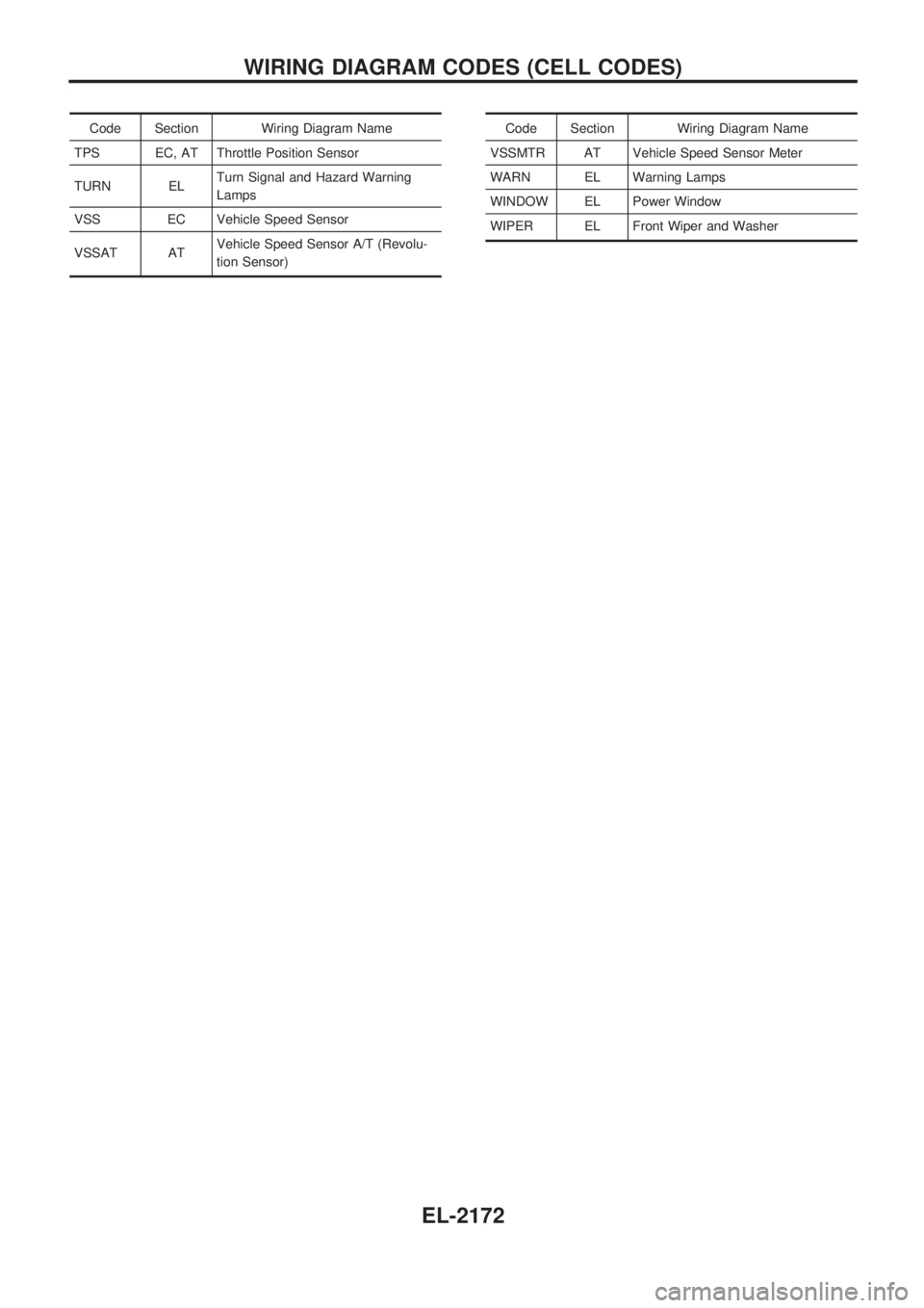
Code Section Wiring Diagram Name
TPS EC, AT Throttle Position Sensor
TURN ELTurn Signal and Hazard Warning
Lamps
VSS EC Vehicle Speed Sensor
VSSAT ATVehicle Speed Sensor A/T (Revolu-
tion Sensor)Code Section Wiring Diagram Name
VSSMTR AT Vehicle Speed Sensor Meter
WARN EL Warning Lamps
WINDOW EL Power Window
WIPER EL Front Wiper and Washer
WIRING DIAGRAM CODES (CELL CODES)
EL-2172
Page 254 of 666
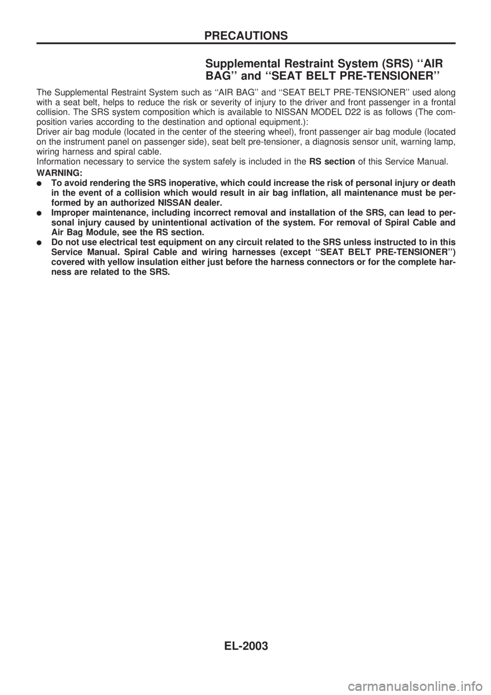
Supplemental Restraint System (SRS) ``AIR
BAG'' and ``SEAT BELT PRE-TENSIONER''
The Supplemental Restraint System such as ``AIR BAG'' and ``SEAT BELT PRE-TENSIONER'' used along
with a seat belt, helps to reduce the risk or severity of injury to the driver and front passenger in a frontal
collision. The SRS system composition which is available to NISSAN MODEL D22 is as follows (The com-
position varies according to the destination and optional equipment.):
Driver air bag module (located in the center of the steering wheel), front passenger air bag module (located
on the instrument panel on passenger side), seat belt pre-tensioner, a diagnosis sensor unit, warning lamp,
wiring harness and spiral cable.
Information necessary to service the system safely is included in theRS sectionof this Service Manual.
WARNING:
lTo avoid rendering the SRS inoperative, which could increase the risk of personal injury or death
in the event of a collision which would result in air bag inflation, all maintenance must be per-
formed by an authorized NISSAN dealer.
lImproper maintenance, including incorrect removal and installation of the SRS, can lead to per-
sonal injury caused by unintentional activation of the system. For removal of Spiral Cable and
Air Bag Module, see the RS section.
lDo not use electrical test equipment on any circuit related to the SRS unless instructed to in this
Service Manual. Spiral Cable and wiring harnesses (except ``SEAT BELT PRE-TENSIONER'')
covered with yellow insulation either just before the harness connectors or for the complete har-
ness are related to the SRS.
PRECAUTIONS
EL-2003
Page 312 of 666
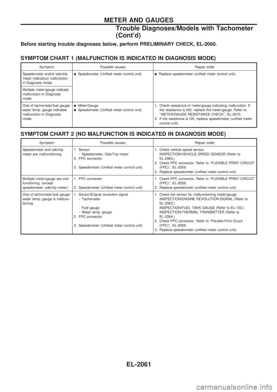
Before starting trouble diagnoses below, perform PRELIMINARY CHECK, EL-2060.
SYMPTOM CHART 1 (MALFUNCTION IS INDICATED IN DIAGNOSIS MODE)
Symptom Possible causes Repair order
Speedometer and/or odo/trip
meter indicate(s) malfunction
in Diagnosis mode.
lSpeedometer (Unified meter control unit)lReplace speedometer (unified meter control unit).
Multiple meter/gauge indicate
malfunction in Diagnosis
mode.
One of tachometer/fuel gauge/
water temp. gauge indicates
malfunction in Diagnosis
mode.
lMeter/GaugelSpeedometer (Unified meter control unit)1. Check resistance of meter/gauge indicating malfunction. If
the resistance is NG, replace the meter/gauge. Refer to
``METER/GAUGE RESISTANCE CHECK'', EL-2070.
2. If the resistance is OK, replace speedometer (unified meter
control unit).
SYMPTOM CHART 2 (NO MALFUNCTION IS INDICATED IN DIAGNOSIS MODE)
Symptom Possible causes Repair order
Speedometer and odo/trip
meter are malfunctioning.1. Sensor
- Speedometer, Odo/Trip meter
2. FPC connector
3. Speedometer (Unified meter control unit)1. Check vehicle speed sensor.
INSPECTION/VEHICLE SPEED SENSOR (Refer to
EL-2063.)
2. Check FPC connector. Refer to ``FLEXIBLE PRINT CIRCUIT
(FPC)'', EL-2059.
3. Replace speedometer (unified meter control unit).
Multiple meter/gauge are mal-
functioning. (except
speedometer, odo/trip meter)1. FPC connector
2. Speedometer (Unified meter control unit)1. Check FPC connector. Refer to ``FLEXIBLE PRINT CIRCUIT
(FPC)'', EL-2059.
2. Replace speedometer (unified meter control unit).
One of tachometer/fuel gauge/
water temp. gauge is malfunc-
tioning.1. Sensor/Engine revolution signal
- Tachometer
- Fuel gauge
- Water temp. gauge
2. FPC connector
3. Speedometer (Unified meter control unit)1. Check the sensor for malfunctioning meter/gauge.
INSPECTION/ENGINE REVOLUTION SIGNAL (Refer to
EL-2063.)
INSPECTION/FUEL TANK GAUGE (Refer to EL-102.)
INSPECTION/THERMAL TRANSMITTER (Refer to
EL-2064.)
2. Check FPC connector. Refer to ``Flexible Print Circuit
(FPC)'', EL-2059.
3. Replace speedometer (unified meter control unit).
METER AND GAUGES
Trouble Diagnoses/Models with Tachometer
(Cont'd)
EL-2061
Page 314 of 666
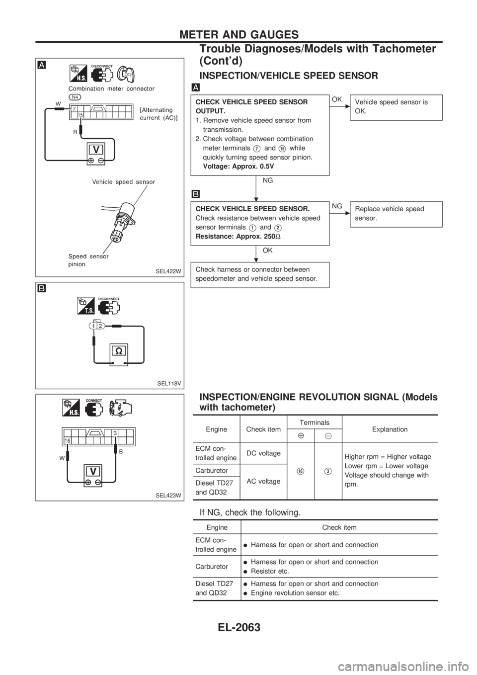
INSPECTION/VEHICLE SPEED SENSOR
CHECK VEHICLE SPEED SENSOR
OUTPUT.
1. Remove vehicle speed sensor from
transmission.
2. Check voltage between combination
meter terminals
V7andV15while
quickly turning speed sensor pinion.
Voltage: Approx. 0.5V
NG
cOK
Vehicle speed sensor is
OK.
CHECK VEHICLE SPEED SENSOR.
Check resistance between vehicle speed
sensor terminals
V1andV2.
Resistance: Approx. 250W
OK
cNG
Replace vehicle speed
sensor.
Check harness or connector between
speedometer and vehicle speed sensor.
INSPECTION/ENGINE REVOLUTION SIGNAL (Models
with tachometer)
Engine Check itemTerminals
ExplanationÅ@
ECM con-
trolled engineDC voltage
V16V3
Higher rpm = Higher voltage
Lower rpm = Lower voltage
Voltage should change with
rpm. Carburetor
AC voltage
Diesel TD27
and QD32
If NG, check the following.
Engine Check item
ECM con-
trolled engine
lHarness for open or short and connection
Carburetor
lHarness for open or short and connection
lResistor etc.
Diesel TD27
and QD32
lHarness for open or short and connection
lEngine revolution sensor etc.
SEL422W
SEL118V
SEL423W
.
.
METER AND GAUGES
Trouble Diagnoses/Models with Tachometer
(Cont'd)
EL-2063
Page 315 of 666
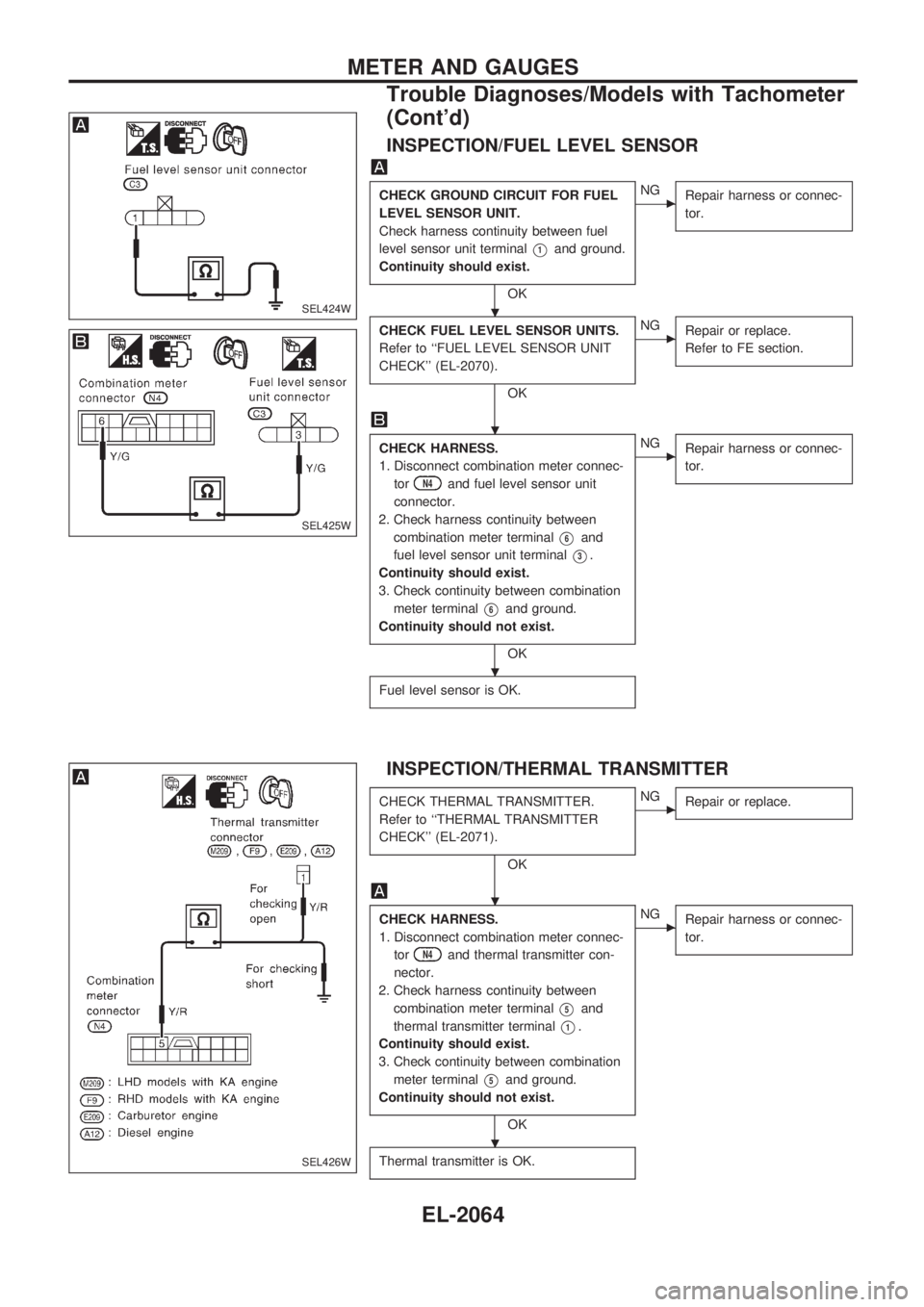
INSPECTION/FUEL LEVEL SENSOR
CHECK GROUND CIRCUIT FOR FUEL
LEVEL SENSOR UNIT.
Check harness continuity between fuel
level sensor unit terminal
V1and ground.
Continuity should exist.
OK
cNG
Repair harness or connec-
tor.
CHECK FUEL LEVEL SENSOR UNITS.
Refer to ``FUEL LEVEL SENSOR UNIT
CHECK'' (EL-2070).
OK
cNG
Repair or replace.
Refer to FE section.
CHECK HARNESS.
1. Disconnect combination meter connec-
tor
N4and fuel level sensor unit
connector.
2. Check harness continuity between
combination meter terminal
V6and
fuel level sensor unit terminal
V3.
Continuity should exist.
3. Check continuity between combination
meter terminal
V6and ground.
Continuity should not exist.
OK
cNG
Repair harness or connec-
tor.
Fuel level sensor is OK.
INSPECTION/THERMAL TRANSMITTER
CHECK THERMAL TRANSMITTER.
Refer to ``THERMAL TRANSMITTER
CHECK'' (EL-2071).
OK
cNG
Repair or replace.
CHECK HARNESS.
1. Disconnect combination meter connec-
tor
N4and thermal transmitter con-
nector.
2. Check harness continuity between
combination meter terminal
V5and
thermal transmitter terminal
V1.
Continuity should exist.
3. Check continuity between combination
meter terminal
V5and ground.
Continuity should not exist.
OK
cNG
Repair harness or connec-
tor.
Thermal transmitter is OK.
SEL424W
SEL425W
SEL426W
.
.
.
.
.
METER AND GAUGES
Trouble Diagnoses/Models with Tachometer
(Cont'd)
EL-2064
Page 317 of 666
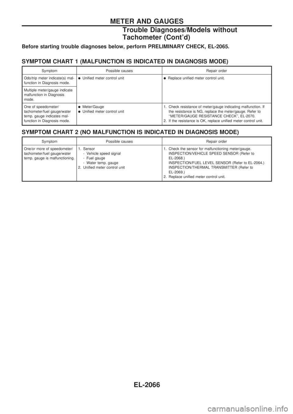
Before starting trouble diagnoses below, perform PRELIMINARY CHECK, EL-2065.
SYMPTOM CHART 1 (MALFUNCTION IS INDICATED IN DIAGNOSIS MODE)
Symptom Possible causes Repair order
Odo/trip meter indicate(s) mal-
function in Diagnosis mode.
lUnified meter control unitlReplace unified meter control unit.
Multiple meter/gauge indicate
malfunction in Diagnosis
mode.
One of speedometer/
tachometer/fuel gauge/water
temp. gauge indicates mal-
function in Diagnosis mode.
lMeter/GaugelUnified meter control unit1. Check resistance of meter/gauge indicating malfunction. If
the resistance is NG, replace the meter/gauge. Refer to
``METER/GAUGE RESISTANCE CHECK'', EL-2070.
2. If the resistance is OK, replace unified meter control unit.
SYMPTOM CHART 2 (NO MALFUNCTION IS INDICATED IN DIAGNOSIS MODE)
Symptom Possible causes Repair order
One/or more of speedometer/
tachometer/fuel gauge/water
temp. gauge is malfunctioning.1. Sensor
- Vehicle speed signal
- Fuel gauge
- Water temp. gauge
2. Unified meter control unit1. Check the sensor for malfunctioning meter/gauge.
INSPECTION/VEHICLE SPEED SENSOR (Refer to
EL-2068.)
INSPECTION/FUEL LEVEL SENSOR (Refer to EL-2064.)
INSPECTION/THERMAL TRANSMITTER (Refer to
EL-2069.)
2. Replace unified meter control unit.
METER AND GAUGES
Trouble Diagnoses/Models without
Tachometer (Cont'd)
EL-2066