Page 439 of 666
Removal
1. Raise vehicle and support it with safety stands.
2. Remove engine under cover.
3. Drain engine oil.
4. Remove front final drive together with differential mounting
member. Refer to PD section (ªRemoval and Installationº,
ªFront final driveº) Ð 4WD models only.
5. Remove front suspension member.
6. Remove oil pan bolts.
7. Remove oil pan.
a. Insert Tool between cylinder block and oil pan.
lBe careful not to damage aluminum mating surface.
lDo not insert screwdriver, or oil pan flange will be dam-
aged.
b. Slide Tool by tapping on the side of the Tool with a hammer.
8. Pull out oil pan from front side.
SEM544FB
SEM600F
SEM980F
SEM365EA
OIL PANKA24DE
EM-2011
Page 444 of 666

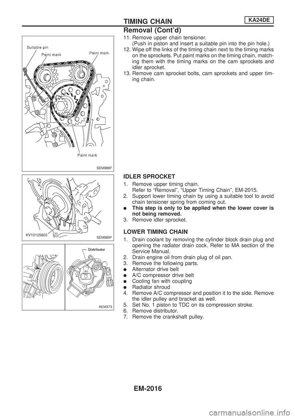
11. Remove upper chain tensioner.
(Push in piston and insert a suitable pin into the pin hole.)
12. Wipe off the links of the timing chain next to the timing marks
on the sprockets. Put paint marks on the timing chain, match-
ing them with the timing marks on the cam sprockets and
idler sprocket.
13. Remove cam sprocket bolts, cam sprockets and upper tim-
ing chain.
IDLER SPROCKET
1. Remove upper timing chain.
Refer to ªRemovalº, ªUpper Timing Chainº, EM-2015.
2. Support lower timing chain by using a suitable tool to avoid
chain tensioner spring from coming out.
lThis step is only to be applied when the lower cover is
not being removed.
3. Remove idler sprocket.
LOWER TIMING CHAIN
1. Drain coolant by removing the cylinder block drain plug and
opening the radiator drain cock. Refer to MA section of the
Service Manual.
2. Drain engine oil from drain plug of oil pan.
3. Remove the following parts.
lAlternator drive belt
lA/C compressor drive belt
lCooling fan with coupling
lRadiator shroud
4. Remove A/C compressor and position it to the side. Remove
the idler pulley and bracket as well.
5. Set No. 1 piston to TDC on its compression stroke.
6. Remove distributor.
7. Remove the crankshaft pulley.
SEM988F
SEM989F
AEM373
TIMING CHAINKA24DE
Removal (Cont'd)
EM-2016
Page 453 of 666

CAUTION:
lWhen installing camshafts, chain tensioners, oil seals,
or other sliding parts, lubricate contacting surfaces with
new engine oil.
lApply new engine oil to threads and seat surfaces when
installing cylinder head, camshaft sprocket, crankshaft
pulley, and camshaft bracket.
lAttach tags to valve lifters so as not to mix them up.
lBefore removing camshaft and idler sprockets, apply
paint marks to them for retiming.
Removal
1. Drain coolant from radiator and cylinder block. Refer to MA
section (ªChanging Engine Coolantº, ªENGINE MAINTE-
NANCEº).
2. Remove upper timing chain and idler sprocket.
lRefer to ªUPPER TIMING CHAINº (EM-2015) and ªIDLER
SPROCKETº (EM-2016), ªRemovalº, ªTIMING CHAINº.
lFor retiming during cylinder head removal/installation,
apply paint marks to camshaft sprockets, upper timing
chain, lower timing chain and idler sprocket.
3. Remove camshaft brackets and camshafts.
lMark the original positions of these parts for reassem-
bly.
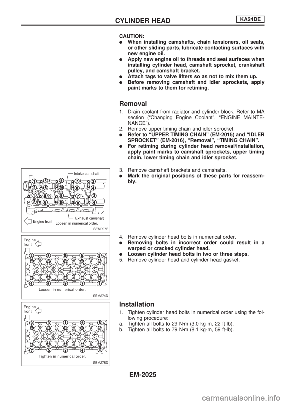
4. Remove cylinder head bolts in numerical order.
lRemoving bolts in incorrect order could result in a
warped or cracked cylinder head.
lLoosen cylinder head bolts in two or three steps.
5. Remove cylinder head and cylinder head gasket.
Installation
1. Tighten cylinder head bolts in numerical order using the fol-
lowing procedure:
a. Tighten all bolts to 29 Nzm (3.0 kg-m, 22 ft-lb).
b. Tighten all bolts to 79 Nzm (8.1 kg-m, 59 ft-lb).
SEM997F
SEM274D
SEM275D
CYLINDER HEADKA24DE
EM-2025
Page 464 of 666

WARNING:
lPosition vehicle on a flat and solid surface.
lPlace chocks at front and back of rear wheels.
lDo not remove engine until exhaust system has com-
pletely cooled off.
Otherwise, you may burn yourself and/or fire may break
out in fuel line.
lBefore disconnecting fuel hose, release fuel pressure.
Refer to EC section (ªFuel Pressure Releaseº, ªBASIC
SERVICE PROCEDUREº).
lBe sure to hoist engine and transmission in a safe man-
ner.
lFor engines not equipped with engine slingers, attach
proper slingers and bolts described in PARTS CATA-
LOG.
CAUTION:
lWhen lifting engine, be sure to clear surrounding parts.
Take special care near accelerator wire casing, brake
lines and brake master cylinder.
lIn hoisting the engine, always use engine slingers in a
safe manner.
lFor 4WD models, apply sealant between engine and
transmission. Refer to MT section (ªRemoval and Instal-
lationº).
Removal
1. Drain coolant from engine block and radiator. Refer to MA
section (ªChanging Engine Coolantº, ªENGINE MAINTE-
NANCEº).
2. Release fuel pressure. Refer to EC section (ªFuel Pressure
Releaseº, ªBASIC SERVICE PROCEDUREº).
3. Remove negative battery cable.
4. Remove hood. Refer to BT section.
5. Remove air cleaner and air duct.
6. Remove power steering drive belt, alternator drive belt and
A/C compressor drive belt.
7. Remove radiator. Refer to LC section (ªRadiatorº, ªENGINE
COOLING SYSTEMº).
8. Remove exhaust manifold heat shield.
9. Disconnect exhaust system from exhaust manifold.
10. Remove A/C compressor from bracket. Refer to HA section
(ªCompressor Mountingº, ªSERVICE PROCEDURESº).
11. Disconnect accelerator wire, vacuum hoses, electrical
connectors, heater hoses and vacuum booster hose.
ENGINE REMOVALKA24DE
EM-2036
Page 467 of 666

CAUTION:
lWhen installing sliding parts (bearings, pistons, etc.),
lubricate contacting surfaces with new engine oil.
lPlace removed parts such as bearings and bearing caps
in their proper order and direction.
lWhen installing connecting rod nuts and main bearing
cap bolts, apply new engine oil to threads and seating
surfaces.
lDo not allow any magnetic materials to contact the ring
gear teeth of flywheel or drive plate.
Disassembly
PISTON AND CRANKSHAFT
1. Place engine on a work stand.
2. Drain coolant and oil.
3. Remove oil pan.
4. Remove timing chain. Refer to ªRemovalº in ªTIMING
CHAINº (EM-2015).
5. Remove water pump.
6. Remove cylinder head.
7. Remove pistons with connecting rods.
8. Remove bearing caps and crankshaft.
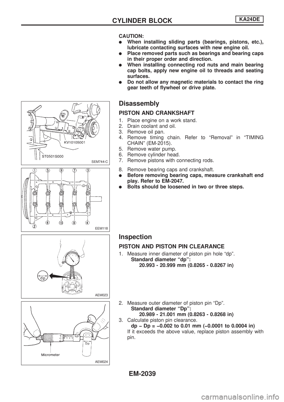
lBefore removing bearing caps, measure crankshaft end
play. Refer to EM-2047.
lBolts should be loosened in two or three steps.
Inspection
PISTON AND PISTON PIN CLEARANCE
1. Measure inner diameter of piston pin hole ªdpº.
Standard diameter ªdpº:
20.993 - 20.999 mm (0.8265 - 0.8267 in)
2. Measure outer diameter of piston pin ªDpº.
Standard diameter ªDpº:
20.989 - 21.001 mm (0.8263 - 0.8268 in)
3. Calculate piston pin clearance.
dp þ Dp = þ0.002 to 0.01 mm (þ0.0001 to 0.0004 in)
If it exceeds the above value, replace piston assembly with
pin.
SEM744-C
EEM118
AEM023
AEM024
CYLINDER BLOCKKA24DE
EM-2039