1999 NISSAN PICK-UP differential
[x] Cancel search: differentialPage 1 of 666
GENERAL INFORMATIONGI
MAINTENANCEMA
ENGINE MECHANICALEM
ENGINE LUBRICATION &
COOLING SYSTEMSLC
ENGINE CONTROL SYSTEMEC
ACCELERATOR CONTROL, FUEL &
EXHAUST SYSTEMSFE
CLUTCHCL
MANUAL TRANSAXLEMT
TRANSFERTF
PROPELLER SHAFT &
DIFFERENTIAL CARRIERPD
FRONT AXLE & FRONT SUSPENSIONFA
REAR AXLE & REAR SUSPENSIONRA
BRAKE SYSTEMBR
STEERING SYSTEMST
RESTRAINT SYSTEMRS
BODY & TRIMBT
HEATER & AIR CONDITIONERHA
ELECTRICAL SYSTEMEL
ALPHABETICAL INDEXIDX
PICKUP
MODEL D22 SERIES
FOREWORD
This supplement contains informa-
tion concerning necessary service
procedures and relevant data for the
model D22 series.
All information, illustrations and spe-
ci®cations contained in this supple-
ment are based on the latest product
information available at the time of
publication. If your NISSAN model
differs from the speci®cations contain-
ed in this supplement, consult your
NISSAN distributor for information.
The right is reserved to make chan-
ges in speci®cations and methods at
any time without notice.
Edition: July 1999
Printing: August 1999 (01)
Publication No.: SM9E-D22BE0E
NISSAN EUROPE S.A.S.
1999 NISSAN EUROPE S.A.S. Printed in the Netherlands
Not to be reproduced in whole or in part without the prior written permission of Nissan Europe S.A.S., Paris, France.
QUICK REFERENCE INDEX
Page 439 of 666
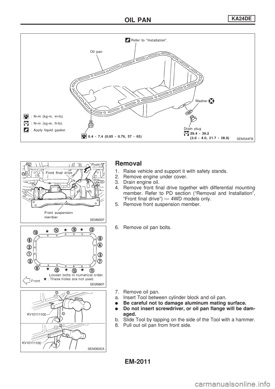
Removal
1. Raise vehicle and support it with safety stands.
2. Remove engine under cover.
3. Drain engine oil.
4. Remove front final drive together with differential mounting
member. Refer to PD section (ªRemoval and Installationº,
ªFront final driveº) Ð 4WD models only.
5. Remove front suspension member.
6. Remove oil pan bolts.
7. Remove oil pan.
a. Insert Tool between cylinder block and oil pan.
lBe careful not to damage aluminum mating surface.
lDo not insert screwdriver, or oil pan flange will be dam-
aged.
b. Slide Tool by tapping on the side of the Tool with a hammer.
8. Pull out oil pan from front side.
SEM544FB
SEM600F
SEM980F
SEM365EA
OIL PANKA24DE
EM-2011
Page 477 of 666
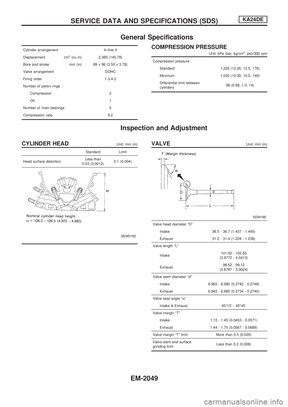
General Specifications
Cylinder arrangement In-line 4
Displacement cm
3(cu in) 2,389 (145.78)
Bore and stroke mm (in) 89 x 96 (3.50 x 3.78)
Valve arrangement DOHC
Firing order 1-3-4-2
Number of piston rings
Compression 2
Oil 1
Number of main bearings 5
Compression ratio 9.2
COMPRESSION PRESSURE
Unit: kPa (bar, kg/cm2, psi)/300 rpm
Compression pressure
Standard 1,226 (12.26, 12.5, 178)
Minimum 1,030 (10.30, 10.5, 149)
Differential limit between
cylinders98 (0.98, 1.0, 14)
Inspection and Adjustment
CYLINDER HEADUnit: mm (in)
Standard Limit
Head surface distortionLess than
0.03 (0.0012)0.1 (0.004)
SEM519E
VALVEUnit: mm (in)
SEM188
Valve head diameter ªDº
Intake 36.5 - 36.7 (1.437 - 1.445)
Exhaust 31.2 - 31.4 (1.228 - 1.236)
Valve length ªLº
Intake101.02 - 102.65
(3.9772 - 4.0413)
Exhaust98.52 - 99.12
(3.8787 - 3.9024)
Valve stem diameter ªdº
Intake 6.965 - 6.980 (0.2742 - 0.2748)
Exhaust 6.945 - 6.960 (0.2734 - 0.2740)
Valve seat angle ªaº
Intake & Exhaust 45É15¢- 45É45¢
Valve margin ªTº
Intake 1.15 - 1.45 (0.0453 - 0.0571)
Exhaust 1.44 - 1.75 (0.0567 - 0.0689)
Valve margin ªTº limit More than 0.5 (0.020)
Valve stem end surface
grinding limitLess than 0.2 (0.008)
SERVICE DATA AND SPECIFICATIONS (SDS)KA24DE
EM-2049
Page 497 of 666
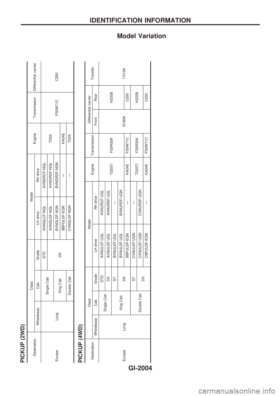
Model Variation
PICKUP (2WD)
DestinationClass Model
Engine Transmission Differential carrier
Wheelbase Cab Grade LH drive RH drive
Europe LongSingle CabSTD AVNGLCF-NQL AVNGRCF-NQL
TD25
FS5W71C C200
DXAVNGLDF-NQL AVNGRDF-NQL
King CabBVNGLDF-NQN BVNGRDF-NQN
BBFGLDF-EQN Ð KA24E
Double Cab CVNGLDF-NQN Ð TD25
PICKUP (4WD)DestinationClass Model
Engine TransmissionDifferential carrier
Transfer
Wheelbase Cab Grade LH drive RH drive Front Rear
Europe LongSingle CabSTD AVNULCF-UQL AVNURCF-UQL
TD25Ti FS5R30A
R180AH233B
TX10A DX AVNULDF-UQL AVNURDF-UQL
King CabST BVNULEF-UQL Ð
DXBVNULDF-UQL BVNURDF-UQN
BBFULDF-EQN Ð KA24E FS5W71C C200
Double CabST CVNULEF-UQN Ð
TD25Ti FS5R30A H233B
DXCVNULDF-UQN CVNURDF-UQN
CBFULDF-EQN Ð KA24E FS5W71C C200
IDENTIFICATION INFORMATION
GI-2004
Page 590 of 666
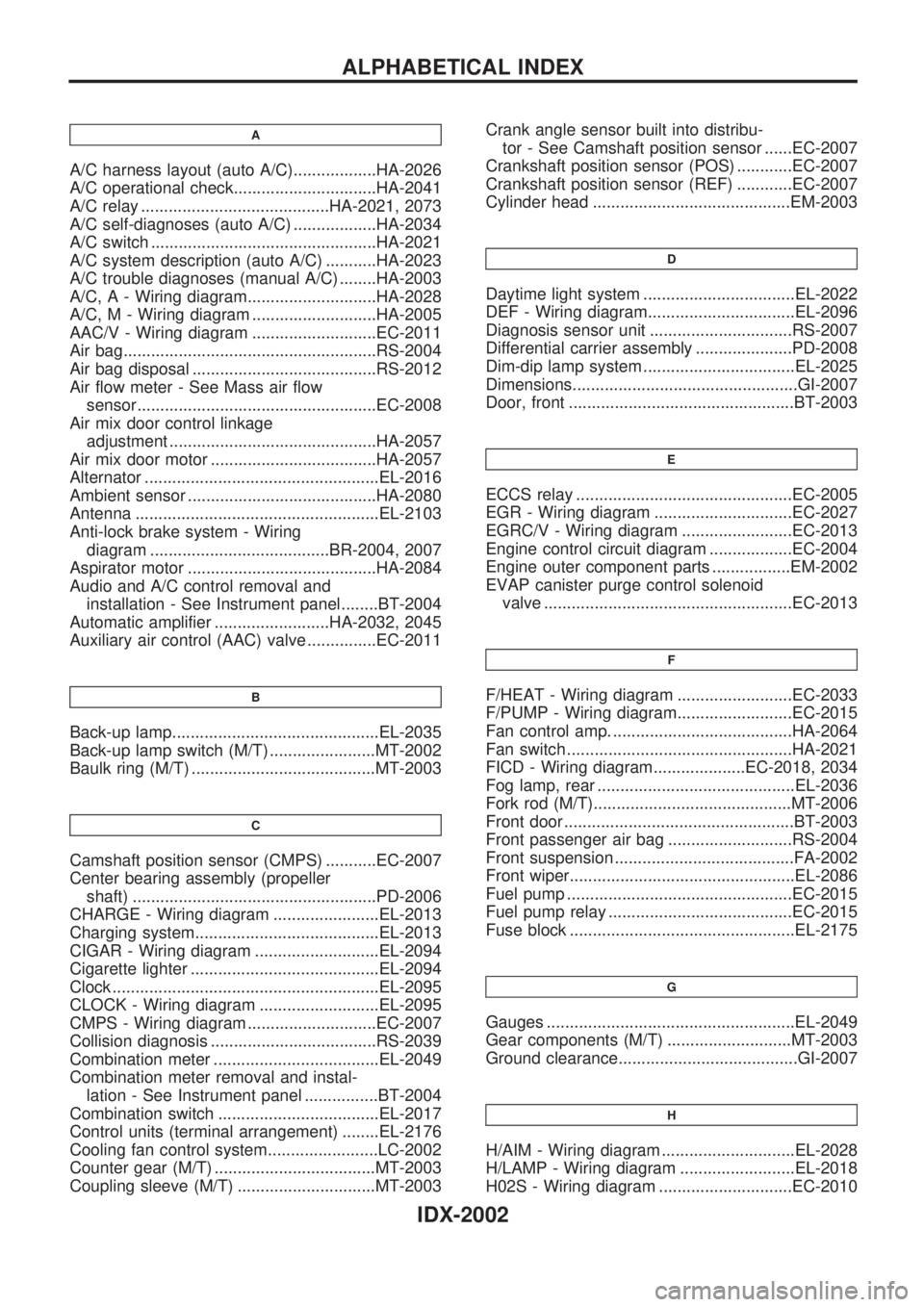
A
A/C harness layout (auto A/C)..................HA-2026
A/C operational check...............................HA-2041
A/C relay .........................................HA-2021, 2073
A/C self-diagnoses (auto A/C) ..................HA-2034
A/C switch .................................................HA-2021
A/C system description (auto A/C) ...........HA-2023
A/C trouble diagnoses (manual A/C) ........HA-2003
A/C, A - Wiring diagram............................HA-2028
A/C, M - Wiring diagram ...........................HA-2005
AAC/V - Wiring diagram ...........................EC-2011
Air bag.......................................................RS-2004
Air bag disposal ........................................RS-2012
Air flow meter - See Mass air flow
sensor....................................................EC-2008
Air mix door control linkage
adjustment .............................................HA-2057
Air mix door motor ....................................HA-2057
Alternator ...................................................EL-2016
Ambient sensor .........................................HA-2080
Antenna .....................................................EL-2103
Anti-lock brake system - Wiring
diagram .......................................BR-2004, 2007
Aspirator motor .........................................HA-2084
Audio and A/C control removal and
installation - See Instrument panel........BT-2004
Automatic amplifier .........................HA-2032, 2045
Auxiliary air control (AAC) valve ...............EC-2011
B
Back-up lamp.............................................EL-2035
Back-up lamp switch (M/T) .......................MT-2002
Baulk ring (M/T) ........................................MT-2003
C
Camshaft position sensor (CMPS) ...........EC-2007
Center bearing assembly (propeller
shaft) .....................................................PD-2006
CHARGE - Wiring diagram .......................EL-2013
Charging system........................................EL-2013
CIGAR - Wiring diagram ...........................EL-2094
Cigarette lighter .........................................EL-2094
Clock ..........................................................EL-2095
CLOCK - Wiring diagram ..........................EL-2095
CMPS - Wiring diagram ............................EC-2007
Collision diagnosis ....................................RS-2039
Combination meter ....................................EL-2049
Combination meter removal and instal-
lation - See Instrument panel ................BT-2004
Combination switch ...................................EL-2017
Control units (terminal arrangement) ........EL-2176
Cooling fan control system........................LC-2002
Counter gear (M/T) ...................................MT-2003
Coupling sleeve (M/T) ..............................MT-2003Crank angle sensor built into distribu-
tor - See Camshaft position sensor ......EC-2007
Crankshaft position sensor (POS) ............EC-2007
Crankshaft position sensor (REF) ............EC-2007
Cylinder head ...........................................EM-2003
D
Daytime light system .................................EL-2022
DEF - Wiring diagram................................EL-2096
Diagnosis sensor unit ...............................RS-2007
Differential carrier assembly .....................PD-2008
Dim-dip lamp system .................................EL-2025
Dimensions.................................................GI-2007
Door, front .................................................BT-2003
E
ECCS relay ...............................................EC-2005
EGR - Wiring diagram ..............................EC-2027
EGRC/V - Wiring diagram ........................EC-2013
Engine control circuit diagram ..................EC-2004
Engine outer component parts .................EM-2002
EVAP canister purge control solenoid
valve ......................................................EC-2013
F
F/HEAT - Wiring diagram .........................EC-2033
F/PUMP - Wiring diagram.........................EC-2015
Fan control amp. .......................................HA-2064
Fan switch .................................................HA-2021
FICD - Wiring diagram....................EC-2018, 2034
Fog lamp, rear ...........................................EL-2036
Fork rod (M/T)...........................................MT-2006
Front door ..................................................BT-2003
Front passenger air bag ...........................RS-2004
Front suspension .......................................FA-2002
Front wiper.................................................EL-2086
Fuel pump .................................................EC-2015
Fuel pump relay ........................................EC-2015
Fuse block .................................................EL-2175
G
Gauges ......................................................EL-2049
Gear components (M/T) ...........................MT-2003
Ground clearance.......................................GI-2007
H
H/AIM - Wiring diagram .............................EL-2028
H/LAMP - Wiring diagram .........................EL-2018
H02S - Wiring diagram .............................EC-2010
ALPHABETICAL INDEX
IDX-2002
Page 598 of 666
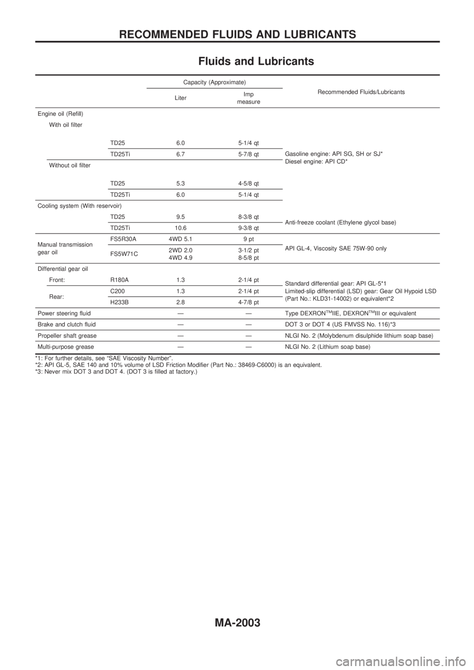
Fluids and Lubricants
Capacity (Approximate)
Recommended Fluids/Lubricants
LiterImp
measure
Engine oil (Refill)
With oil filter
TD25 6.0 5-1/4 qt
Gasoline engine: API SG, SH or SJ*
Diesel engine: API CD* TD25Ti 6.7 5-7/8 qt
Without oil filter
TD25 5.3 4-5/8 qt
TD25Ti 6.0 5-1/4 qt
Cooling system (With reservoir)
TD25 9.5 8-3/8 qt
Anti-freeze coolant (Ethylene glycol base)
TD25Ti 10.6 9-3/8 qt
Manual transmission
gear oilFS5R30A 4WD 5.1 9 pt
API GL-4, Viscosity SAE 75W-90 only
FS5W71C2WD 2.0
4WD 4.93-1/2 pt
8-5/8 pt
Differential gear oil
Front: R180A 1.3 2-1/4 pt
Standard differential gear: API GL-5*1
Limited-slip differential (LSD) gear: Gear Oil Hypoid LSD
(Part No.: KLD31-14002) or equivalent*2 Rear:C200 1.3 2-1/4 pt
H233B 2.8 4-7/8 pt
Power steering fluid Ð Ð Type DEXRON
TMIIE, DEXRONTMIII or equivalent
Brake and clutch fluid Ð Ð DOT 3 or DOT 4 (US FMVSS No. 116)*3
Propeller shaft grease Ð Ð NLGI No. 2 (Molybdenum disulphide lithium soap base)
Multi-purpose grease Ð Ð NLGI No. 2 (Lithium soap base)
*1: For further details, see ªSAE Viscosity Numberº.
*2: API GL-5, SAE 140 and 10% volume of LSD Friction Modifier (Part No.: 38469-C6000) is an equivalent.
*3: Never mix DOT 3 and DOT 4. (DOT 3 is filled at factory.)
RECOMMENDED FLUIDS AND LUBRICANTS
MA-2003
Page 599 of 666
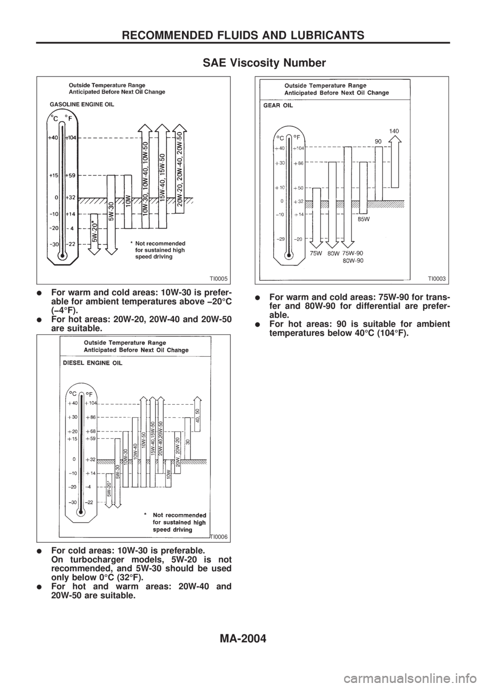
SAE Viscosity Number
lFor warm and cold areas: 10W-30 is prefer-
able for ambient temperatures above þ20ÉC
(þ4ÉF).
lFor hot areas: 20W-20, 20W-40 and 20W-50
are suitable.
lFor cold areas: 10W-30 is preferable.
On turbocharger models, 5W-20 is not
recommended, and 5W-30 should be used
only below 0ÉC (32ÉF).
lFor hot and warm areas: 20W-40 and
20W-50 are suitable.
lFor warm and cold areas: 75W-90 for trans-
fer and 80W-90 for differential are prefer-
able.
lFor hot areas: 90 is suitable for ambient
temperatures below 40ÉC (104ÉF).
TI0005
TI0006
TI0003
RECOMMENDED FLUIDS AND LUBRICANTS
MA-2004
Page 607 of 666
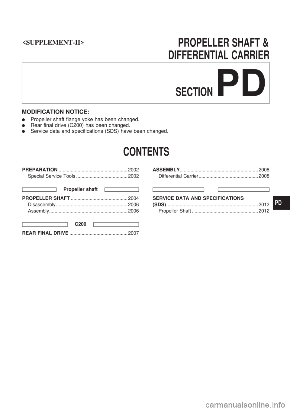
PROPELLERSHAFT&
DIFFERENTIAL CARRIER
SECTION
PD
MODIFICATION NOTICE:
lPropeller shaft flange yoke has been changed.
lRear final drive (C200) has been changed.
lService data and specifications (SDS) have been changed.
CONTENTS
PREPARATION ................................................... 2002
Special Service Tools ...................................... 2002
Propeller shaft
PROPELLER SHAFT .......................................... 2004
Disassembly ..................................................... 2006
Assembly.......................................................... 2006
C200
REAR FINAL DRIVE ........................................... 2007 ASSEMBLY
.......................................................... 2008
Differential Carrier ............................................ 2008
SERVICE DATA AND SPECIFICATIONS
(SDS) .................................................................... 2012
Propeller Shaft ................................................. 2012
PD