1999 NISSAN PICK-UP service
[x] Cancel search: servicePage 1 of 666
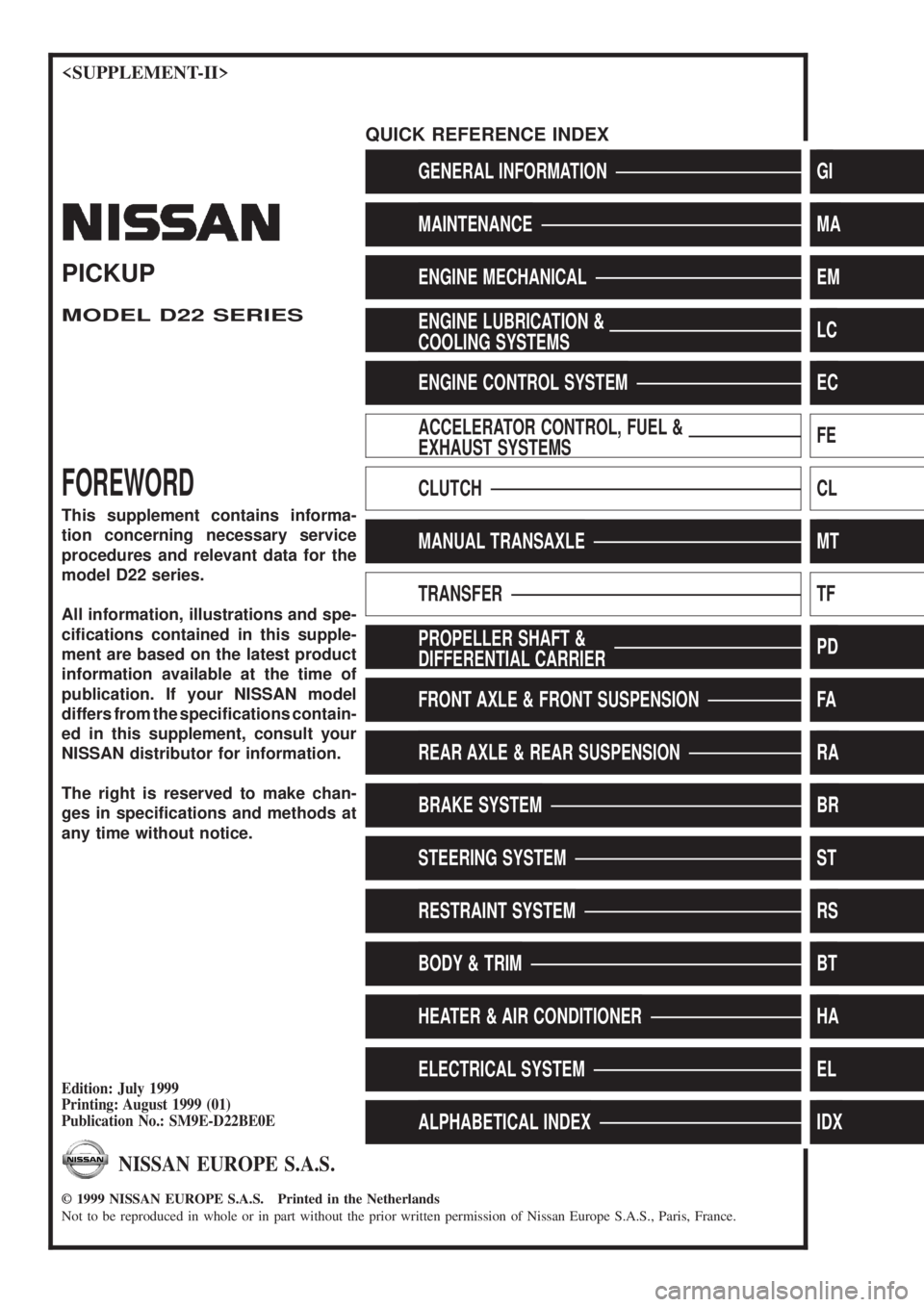
GENERAL INFORMATIONGI
MAINTENANCEMA
ENGINE MECHANICALEM
ENGINE LUBRICATION &
COOLING SYSTEMSLC
ENGINE CONTROL SYSTEMEC
ACCELERATOR CONTROL, FUEL &
EXHAUST SYSTEMSFE
CLUTCHCL
MANUAL TRANSAXLEMT
TRANSFERTF
PROPELLER SHAFT &
DIFFERENTIAL CARRIERPD
FRONT AXLE & FRONT SUSPENSIONFA
REAR AXLE & REAR SUSPENSIONRA
BRAKE SYSTEMBR
STEERING SYSTEMST
RESTRAINT SYSTEMRS
BODY & TRIMBT
HEATER & AIR CONDITIONERHA
ELECTRICAL SYSTEMEL
ALPHABETICAL INDEXIDX
PICKUP
MODEL D22 SERIES
FOREWORD
This supplement contains informa-
tion concerning necessary service
procedures and relevant data for the
model D22 series.
All information, illustrations and spe-
ci®cations contained in this supple-
ment are based on the latest product
information available at the time of
publication. If your NISSAN model
differs from the speci®cations contain-
ed in this supplement, consult your
NISSAN distributor for information.
The right is reserved to make chan-
ges in speci®cations and methods at
any time without notice.
Edition: July 1999
Printing: August 1999 (01)
Publication No.: SM9E-D22BE0E
NISSAN EUROPE S.A.S.
1999 NISSAN EUROPE S.A.S. Printed in the Netherlands
Not to be reproduced in whole or in part without the prior written permission of Nissan Europe S.A.S., Paris, France.
QUICK REFERENCE INDEX
Page 2 of 666
FOREWORD
This manual contains maintenance and repair procedures for NISSAN
PICKUP, model D22 series.
In order to assure your safety and the efficient functioning of the vehicle,
this manual should be read thoroughly. It is especially important that the
PRECAUTIONS in the GI section be completely understood before starting
any repair task.
All information in this manual is based on the latest product information
at the time of publication. The right is reserved to make changes in speci-
®cations and methods at any time without notice.
IMPORTANT SAFETY NOTICE
The proper performance of service is essential for both the safety of the
technician and the efficient functioning of the vehicle.
The service methods in this Service Manual are described in such a man-
ner that the service may be performed safely and accurately.
Service varies with the procedures used, the skills of the technician and the
tools and parts available. Accordingly, anyone using service procedures,
tools or parts which are not speci®cally recommended by NISSAN must
®rst completely satisfy himself that neither his safety nor the vehicle's
safety will be jeopardized by the service method selected.
NISSAN EUROPE S.A.S.
Service Engineering Section
Paris, France
Page 3 of 666
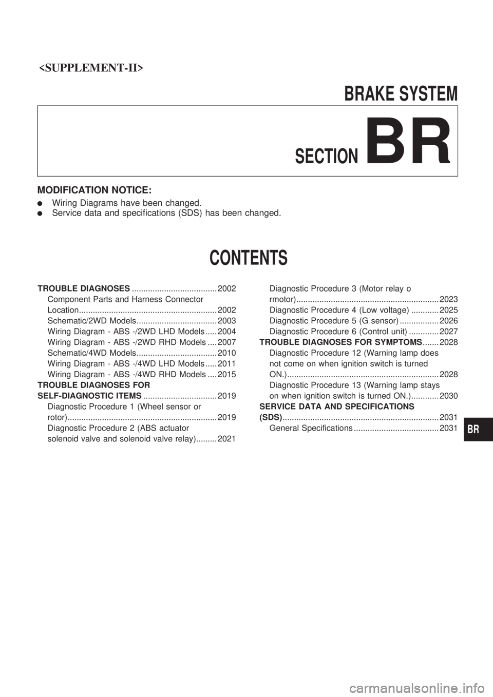
BRAKESYSTEM
SECTION
BR
MODIFICATION NOTICE:
lWiring Diagrams have been changed.
lService data and specifications (SDS) has been changed.
CONTENTS
TROUBLE DIAGNOSES ..................................... 2002
Component Parts and Harness Connector
Location............................................................ 2002
Schematic/2WD Models................................... 2003
Wiring Diagram - ABS -/2WD LHD Models ..... 2004
Wiring Diagram - ABS -/2WD RHD Models .... 2007
Schematic/4WD Models................................... 2010
Wiring Diagram - ABS -/4WD LHD Models ..... 2011
Wiring Diagram - ABS -/4WD RHD Models .... 2015
TROUBLE DIAGNOSES FOR
SELF-DIAGNOSTIC ITEMS ................................ 2019
Diagnostic Procedure 1 (Wheel sensor or
rotor)................................................................. 2019
Diagnostic Procedure 2 (ABS actuator
solenoid valve and solenoid valve relay)......... 2021 Diagnostic Procedure 3 (Motor relay o
rmotor).............................................................. 2023
Diagnostic Procedure 4 (Low voltage) ............ 2025
Diagnostic Procedure 5 (G sensor) ................. 2026
Diagnostic Procedure 6 (Control unit) ............. 2027
TROUBLE DIAGNOSES FOR SYMPTOMS ....... 2028
Diagnostic Procedure 12 (Warning lamp does
not come on when ignition switch is turned
ON.).................................................................. 2028
Diagnostic Procedure 13 (Warning lamp stays
on when ignition switch is turned ON.)............ 2030
SERVICE DATA AND SPECIFICATIONS
(SDS) .................................................................... 2031
General Specifications ..................................... 2031
BR
Page 23 of 666

Diagnostic Procedure 2 (ABS actuator
solenoid valve and solenoid valve relay)
Malfunction code No. 41, 45, 55, 42, 46, 56, 63
CHECK FUSIBLE LINK.
-------------------------------------------------------------------------------------------------------------------------------------------------------------------------------------------------------------------------------------------------------------------------------------------------------------
Check 30A fusible link
e
. For fusible link
layout, refer to POWER SUPPLY ROUT-
ING in EL section.
OK
cNG
VA(Go to next page.)
CHECK FUSE.
-------------------------------------------------------------------------------------------------------------------------------------------------------------------------------------------------------------------------------------------------------------------------------------------------------------
Check 10A fuse
18. For fuse layout, refer
to POWER SUPPLY ROUTING in EL
section.
OK
cNG
VB(Go to next page.)
CHECK CONNECTOR.
-------------------------------------------------------------------------------------------------------------------------------------------------------------------------------------------------------------------------------------------------------------------------------------------------------------
1. Disconnect ABS actuator and electric
unit connector. Check terminals for
damage or loose connection. Then
reconnect connector.
2. Carry out self-diagnosis again.
Does warning lamp activate again?
Yes
cNo
Inspection end
CHECK ABS ACTUATOR AND ELEC-
TRIC UNIT GROUND CIRCUIT.
-------------------------------------------------------------------------------------------------------------------------------------------------------------------------------------------------------------------------------------------------------------------------------------------------------------
Refer to ABS ACTUATOR AND ELEC-
TRIC UNIT GROUND in Ground Circuit
Check. Refer to original Service Manual.
OK
cNG
Repair harness and con-
nector.
CHECK SOLENOID VALVE RELAY
POWER SUPPLY CIRCUIT.
-------------------------------------------------------------------------------------------------------------------------------------------------------------------------------------------------------------------------------------------------------------------------------------------------------------
1. Disconnect ABS actuator and electric
unit connector.
2. Check voltage between ABS actuator
and electric unit connector
E4(body
side) terminal
V18and ground.
Battery voltage should exist.
OK
cNG
Check the following.
lHarness connectorE4
lHarness for open or
short between ABS
actuator and electric unit
and fusible link
If NG, repair harness or
connector.
REPLACE.
-------------------------------------------------------------------------------------------------------------------------------------------------------------------------------------------------------------------------------------------------------------------------------------------------------------
Replace ABS actuator and electric unit.
SBR050EA
SBR052E
.
.
.
.
.
TROUBLE DIAGNOSES FOR SELF-DIAGNOSTIC ITEMS
BR-2021
Page 25 of 666
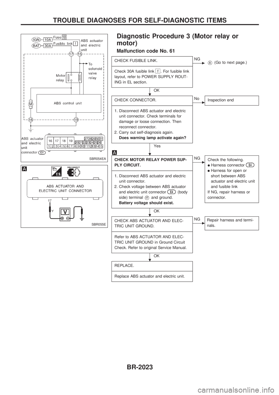
Diagnostic Procedure 3 (Motor relay or
motor)
Malfunction code No. 61
CHECK FUSIBLE LINK.
-------------------------------------------------------------------------------------------------------------------------------------------------------------------------------------------------------------------------------------------------------------------------------------------------------------
Check 30A fusible link
f . For fusible link
layout, refer to POWER SUPPLY ROUT-
ING in EL section.
OK
cNGVA(Go to next page.)
CHECK CONNECTOR.
-------------------------------------------------------------------------------------------------------------------------------------------------------------------------------------------------------------------------------------------------------------------------------------------------------------
1. Disconnect ABS actuator and electric
unit connector. Check terminals for
damage or loose connection. Then
reconnect connector.
2. Carry out self-diagnosis again.
Does warning lamp activate again?
Yes
cNo
Inspection end
CHECK MOTOR RELAY POWER SUP-
PLY CIRCUIT.
-------------------------------------------------------------------------------------------------------------------------------------------------------------------------------------------------------------------------------------------------------------------------------------------------------------
1. Disconnect ABS actuator and electric
unit connector.
2. Check voltage between ABS actuator
and electric unit connector
E4(body
side) terminal
V17and ground.
Battery voltage should exist.
OK
cNG
Check the following.
lHarness connectorE4
lHarness for open or
short between ABS
actuator and electric unit
and fusible link
If NG, repair harness or
connector.
CHECK ABS ACTUATOR AND ELEC-
TRIC UNIT GROUND.
-------------------------------------------------------------------------------------------------------------------------------------------------------------------------------------------------------------------------------------------------------------------------------------------------------------
Refer to ABS ACTUATOR AND ELEC-
TRIC UNIT GROUND in Ground Circuit
Check. Refer to original Service Manual.
OK
cNG
Repair harness and termi-
nals.
REPLACE.
-------------------------------------------------------------------------------------------------------------------------------------------------------------------------------------------------------------------------------------------------------------------------------------------------------------
Replace ABS actuator and electric unit.
SBR054EA
SBR055E
.
.
.
.
TROUBLE DIAGNOSES FOR SELF-DIAGNOSTIC ITEMS
BR-2023
Page 27 of 666

Diagnostic Procedure 4 (Low voltage)
Malfunction code No. 57
CHECK CONNECTOR.
-------------------------------------------------------------------------------------------------------------------------------------------------------------------------------------------------------------------------------------------------------------------------------------------------------------
1. Disconnect ABS actuator and electric
unit connector. Check terminals for
damage or loose connection. Then
reconnect connector.
2. Carry out self-diagnosis again.
Does warning lamp activate again?
Yes
cNo
Inspection end
CHECK ABS CONTROL UNIT POWER
SUPPLY CIRCUIT.
-------------------------------------------------------------------------------------------------------------------------------------------------------------------------------------------------------------------------------------------------------------------------------------------------------------
1. Disconnect ABS actuator and electric
unit connector.
2. Check voltage between ABS actuator
and electric unit connector
E4(body
side) terminal
V15and ground.
Battery voltage should exist when
ignition switch is turned ON.
OK
cNGVA(See below.)
CHECK ABS CONTROL UNIT GROUND.
-------------------------------------------------------------------------------------------------------------------------------------------------------------------------------------------------------------------------------------------------------------------------------------------------------------
Refer to ABS ACTUATOR AND ELEC-
TRIC UNIT GROUND in Ground Circuit
Check. Refer to original Service Manual.
OK
cNG
Repair harness and con-
nector.
CHECK HARNESS CONNECTOR.
-------------------------------------------------------------------------------------------------------------------------------------------------------------------------------------------------------------------------------------------------------------------------------------------------------------
Check ABS actuator and electric unit pin
terminals for damage or the connection of
ABS actuator and electric unit harness
connector. Reconnect ABS actuator and
electric unit harness connector. Then
retest.
VA
CHECK FUSE.
-------------------------------------------------------------------------------------------------------------------------------------------------------------------------------------------------------------------------------------------------------------------------------------------------------------
Check 10A fuse
18. For fuse layout, refer
to POWER SUPPLY ROUTING in EL
section.
OK
cNG
Replace fuse.
CHECK ABS CONTROL UNIT POWER
SUPPLY CIRCUIT.
-------------------------------------------------------------------------------------------------------------------------------------------------------------------------------------------------------------------------------------------------------------------------------------------------------------
Check continuity between battery and
ABS actuator and electric unit connector
E4(body side) terminalV15.
OK
cNG
Check the following.
lHarness connectorE4lHarness for open or
short between ABS
actuator and electric unit
and fuse
If NG, repair harness or
connector.
CHECK BATTERY.
-------------------------------------------------------------------------------------------------------------------------------------------------------------------------------------------------------------------------------------------------------------------------------------------------------------
Check battery. Refer to BATTERY in EL
section.
SBR057EA
SBR058EF
.
.
.
.
.
.
TROUBLE DIAGNOSES FOR SELF-DIAGNOSTIC ITEMS
BR-2025
Page 33 of 666
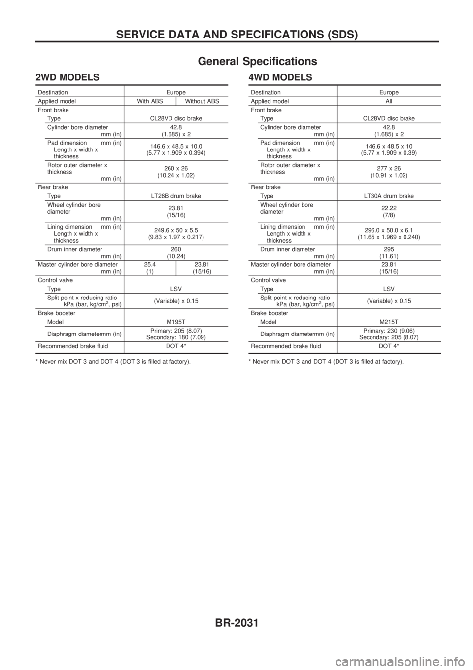
General Specifications
2WD MODELS
Destination Europe
Applied model With ABS Without ABS
Front brake
Type CL28VD disc brake
Cylinder bore diameter
mm (in)42.8
(1.685) x 2
Pad dimension mm (in)
Length x width x
thickness146.6 x 48.5 x 10.0
(5.77 x 1.909 x 0.394)
Rotor outer diameter x
thickness
mm (in)260x26
(10.24 x 1.02)
Rear brake
Type LT26B drum brake
Wheel cylinder bore
diameter
mm (in)23.81
(15/16)
Lining dimension mm (in)
Length x width x
thickness249.6 x 50 x 5.5
(9.83 x 1.97 x 0.217)
Drum inner diameter
mm (in)260
(10.24)
Master cylinder bore diameter
mm (in)25.4
(1)23.81
(15/16)
Control valve
Type LSV
Split point x reducing ratio
kPa (bar, kg/cm
2, psi)(Variable) x 0.15
Brake booster
Model M195T
Diaphragm diametermm (in)Primary: 205 (8.07)
Secondary: 180 (7.09)
Recommended brake fluid DOT 4*
* Never mix DOT 3 and DOT 4 (DOT 3 is filled at factory).
4WD MODELS
Destination Europe
Applied model All
Front brake
Type CL28VD disc brake
Cylinder bore diameter
mm (in)42.8
(1.685) x 2
Pad dimension mm (in)
Length x width x
thickness146.6 x 48.5 x 10
(5.77 x 1.909 x 0.39)
Rotor outer diameter x
thickness
mm (in)277x26
(10.91 x 1.02)
Rear brake
Type LT30A drum brake
Wheel cylinder bore
diameter
mm (in)22.22
(7/8)
Lining dimension mm (in)
Length x width x
thickness296.0 x 50.0 x 6.1
(11.65 x 1.969 x 0.240)
Drum inner diameter
mm (in)295
(11.61)
Master cylinder bore diameter
mm (in)23.81
(15/16)
Control valve
Type LSV
Split point x reducing ratio
kPa (bar, kg/cm
2, psi)(Variable) x 0.15
Brake booster
Model M215T
Diaphragm diametermm (in)Primary: 230 (9.06)
Secondary: 205 (8.07)
Recommended brake fluid DOT 4*
* Never mix DOT 3 and DOT 4 (DOT 3 is filled at factory).
SERVICE DATA AND SPECIFICATIONS (SDS)
BR-2031
Page 35 of 666
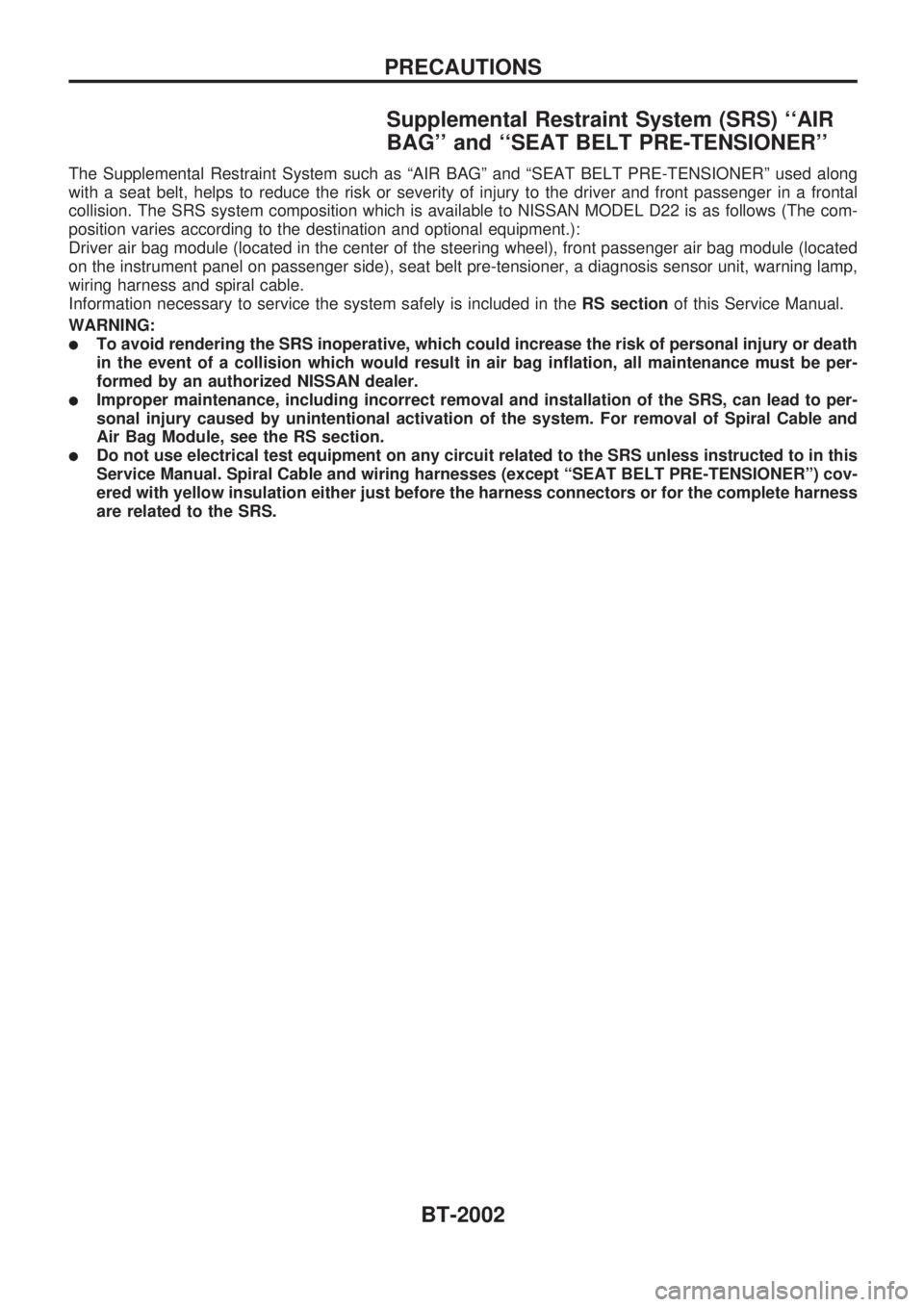
Supplemental Restraint System (SRS) ``AIR
BAG'' and ``SEAT BELT PRE-TENSIONER''
The Supplemental Restraint System such as ªAIR BAGº and ªSEAT BELT PRE-TENSIONERº used along
with a seat belt, helps to reduce the risk or severity of injury to the driver and front passenger in a frontal
collision. The SRS system composition which is available to NISSAN MODEL D22 is as follows (The com-
position varies according to the destination and optional equipment.):
Driver air bag module (located in the center of the steering wheel), front passenger air bag module (located
on the instrument panel on passenger side), seat belt pre-tensioner, a diagnosis sensor unit, warning lamp,
wiring harness and spiral cable.
Information necessary to service the system safely is included in theRS sectionof this Service Manual.
WARNING:
lTo avoid rendering the SRS inoperative, which could increase the risk of personal injury or death
in the event of a collision which would result in air bag inflation, all maintenance must be per-
formed by an authorized NISSAN dealer.
lImproper maintenance, including incorrect removal and installation of the SRS, can lead to per-
sonal injury caused by unintentional activation of the system. For removal of Spiral Cable and
Air Bag Module, see the RS section.
lDo not use electrical test equipment on any circuit related to the SRS unless instructed to in this
Service Manual. Spiral Cable and wiring harnesses (except ªSEAT BELT PRE-TENSIONERº) cov-
ered with yellow insulation either just before the harness connectors or for the complete harness
are related to the SRS.
PRECAUTIONS
BT-2002